
Related Manuals for Kramer F-121UK


Summary of Contents for Kramer F-121UK
- Page 1 K R A ME R E LE CT R O N IC S L T D . USER MANUAL MODEL: F-121UK UXGA / Audio Line Transmitter Mounting Box for Ackermann UK Modular Floor Boxes P/N: 2900-300036 Rev 1...
-
Page 2: Table Of Contents
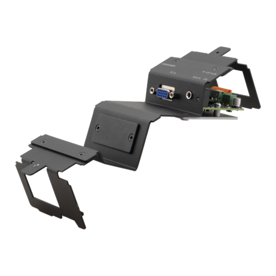
Wiring the CAT 5 LINE IN / LINE OUT RJ-45 Connectors Technical Specifications Figures F igure 1: The F-121UK UXGA / Audio Line Driver Mounting Box (with Brackets) F igure 2: F-121UK Front Panel (without Brackets) F igure 3: F-121UK Fitted in an Ackermann Floor Box... -
Page 3: Introduction
GROUP 7: Scan Converters and Scalers; GROUP 8: Cables and Connectors; GROUP 9: Room Connectivity; GROUP 10: Accessories and Rack Adapters; GROUP 11: Sierra Products. Congratulations on purchasing your Kramer F-121UK UXGA / Audio Line Transmitter Mounting Box for Ackermann UK Modular Floor Boxes which is ideal for: •... -
Page 4: Getting Started
• Avoid interference from neighboring electrical appliances that may adversely influence signal quality • Position your Kramer F-121UK away from moisture, excessive sunlight and dust Caution: No operator serviceable parts inside the unit Use only the Kramer Electronics input power wall... -
Page 5: Overview
It converts the input signals into a twisted pair signal that it transmits to a compatible twisted pair receiver (for example, the Kramer TP-122N). The F-121UK includes one opening (covered by a blank panel) for a single Kramer insert. -
Page 6: Shielded Twisted Pair (Stp) / Unshielded Twisted Pair (Utp)
STP cable that you can afford. Our non-skew-free cable, Kramer BC-STP is intended for analog signals where skewing is not an issue. For cases where there is skewing, our UTP skew-free cable, Kramer BC-XTP, may be used. Bear in mind, though, that we advise using STP cables where possible, since the compliance to electromagnetic interference was tested using those cables. -
Page 7: Ddc Support
The Extended Display Identification Data (EDID) is a data-structure provided by a display, to describe its capabilities to a graphics card (that is connected to the display’s source). The EDID enables the F-121UK to “know” what kind of monitor is connected to the output. The EDID includes the manufacturer’s name, the product type, the timing data supported by the display, the display size, luminance data and (for digital displays only) the pixel mapping data. -
Page 8: Defining The F-121Uk
Defining the F-121UK This section defines the F-121UK. Figure 2: F-121UK Front Panel (without Brackets) Feature Function 8-pin Terminal Block Line Connect to the line in connector on the receiver (see Output Connector (located Section 5.5 inside the mounting box) Power Supply 2-pin Terminal Connect to power supply. -
Page 9: Installing The F-121Uk
Installing the F-121UK To install the F-121UK you have to install the inserts and the transmitter which is connected via TP to a receiver. To install the F-121UK, do the following: • Install the Kramer inserts (see Section 5.1 •... -
Page 10: Installing The F-121Uk Inside The Ackermann Floor Box
3. Separate the two red plastic parts. 4. Unscrew the two screws on each side of the brackets on the F-121UK (four in total) and put the screws to one side (you will need them later; see step... - Page 11 6. Place the plastic parts with the connected brackets over the Ackermann box and screw tight in three places (two underneath and one on top). 7. Place the F-121UK main part over the brackets and tighten to the brackets using the four screws you previously put to one side (in step 4).
-
Page 12: Connecting The Front Panel Ports
An audio source to the AUDIO IN 3.5mm mini jack, for example, using a Kramer C-GMA/GMA cable (VGA 15-pin HD (M) +Audio jack to VGA 15-pin HD (M) +Audio jack). Note that the C-GMA/GMA cable is not supplied with the unit 2. -
Page 13: Wiring The 8-Pin Terminal Block Line Output Connector
Use the connector clips only when removing wires, not when inserting them. Each wire should protrude 9mm (0.35") from the plastic insulation so that it can be easily connected. To prevent the wires crossing, be sure that each wire is fully inserted. F-121UK - Installing the F-121UK... -
Page 14: Wiring The Cat 5 Line In / Line Out Rj-45 Connectors
Orange / White Orange Green / White Blue Blue / White Green Brown / White Brown Pair 1 4 and 5 Pair 2 1 and 2 Pair 3 3 and 6 Pair 4 7 and 8 F-121UK - Installing the F-121UK... -
Page 15: Technical Specifications
With brackets: 7.5cm x 21.2cm x 4.9cm (2.96” x 8.34" x 1.96") W, D, H Without brackets: 7.5cm x 15.1cm x 4.9cm (2.96” x 5.93" x 1.96") W, D, H WEIGHT: 0.19kg (0.42lbs) approx. ACCESSORIES: Power supply Specifications are subject to change without notice at http://www.kramerelectronics.com F-121UK - Technical Specifications... - Page 16 F-121UK...
- Page 17 For the latest information on our products and a list of Kramer distributors, visit our Web site where updates to this user manual may be found. We welcome your questions, comments, and feedback. Web site: www.kramerelectronics.com E-mail: info@kramerel.com SAFETY WARNING...
Need help?
Do you have a question about the F-121UK and is the answer not in the manual?
Questions and answers