
Related Manuals for Aaeon APC-8122 Series


Summary of Contents for Aaeon APC-8122 Series
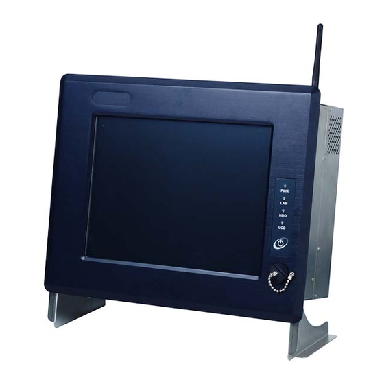
- Page 1 R o b u s t P a n e l P C A P C - 8 1 2 2 APC-8122 ® ® Socket 478 based Intel Pentium 4 and ® Celeron Processors Robust Panel PC With 12.1” TFT LCD & Two PCI expansion slots APC-8122 Series User Manual V1.0...
-
Page 2: Copyright Notice
AAEON assumes no liabilities resulting from errors or omissions in this document, or from the use of the information contained herein. AAEON reserves the right to make changes in the product design without notice to its users. APC-8122 Series User Manual V1.0... -
Page 3: Acknowledgments
ITE is a trademark of Integrated Technology Express, Inc. SiS is a trademark of Silicon Integrated Systems Corp. VIA is a trademark of VIA Technology, Inc. All other product names or trademarks are properties of their respective owners. APC-8122 Series User Manual V1.0... -
Page 4: Packing List
A P C - 8 1 2 2 Packing List Before you begin installing your card, please make sure that the following materials have been shipped: 1 APC-8122 Robust Panel PC 8 Panel mount bracket and screw 1 Easy stand 1 Waterproof sponge... -
Page 5: Safety & Warranty
14. If any of the following situations arises, get the equipment checked by service personnel: a. The power cord or plug is damaged. b. Liquid has penetrated into the equipment. APC-8122 Series User Manual V1.0... - Page 6 In addition, all such combinations – systems – shall comply with the standard IEC 60601-1-1, Safety requirements for medical electrical systems. Equipment not complying with UL 2601-1 shall be kept outside the patient environment, as defined in the standard. APC-8122 Series User Manual V1.0...
-
Page 7: Fcc Safety
This device complies with Part 15 FCC Rules. Operation is subject to the following two conditions: (1) this device may not cause harmful interference, and (2) this device must accept any interference received including interference that may cause undesired operation. APC-8122 Series User Manual V1.0... -
Page 8: Table Of Contents
2.6 Clear CMOS (JP1) ..........27 2.7 Audio Out Select (JP2) .......27 2.8 COM2 Ring/+5V/+12V Selection (JP3) ....28 2.9 COM2 RS-232/422/485 Select (JP4&JP5) ......28 2.10 ATX Power simulate AT Power (JP6) ..........29 2.11 IDE Connector (CN1) APC-8122 Series User Manual V1.0... - Page 9 2.27 Waterproof sponge Installation Chapter 3 BIOS Installation ....46 ........47 3.1 System test and initialization .............48 3.2 Award BIOS Setup ...........50 3.3 Standard CMOS Features ..........50 3.4 Advanced BIOS Features .........50 3.5 Advanced Chipset Features APC-8122 Series User Manual V1.0...
- Page 10 3.14 Exit without saving ..............52 3.15 Limitations Chapter 4 Driver Installation..... 53 ..............54 4.1 Installation ..........56 4.2 LAN Driver Installation ........57 4.3 Card Reader Driver Installation ........57 4.4 Touch screen Driver Installation ..............57 4.5 Limitations APC-8122 Series User Manual V1.0...
-
Page 11: Chapter 1 General Information
R o b u s t P a n e l P C A P C - 8 1 2 2 Chapter General Information APC-8122 Series User Manual V1.0... -
Page 12: Introduction
Processor, supporting FSB up to 400/533MHz. Best performance for multimedia solution AAEON's APC-8122 also supports DDR DRAM up to 1GB, 4X AGP, and 5.1 channels audio output. It can provide the strong multimedia functions. Therefore APC-8122 can be broadly implemented in several markets, such as Point of sale, point of information (Kiosk), and gaming markets. -
Page 13: Features
Processors (FSB 400/533 MHz) Anti-vibration Disk Drive Bay for HDD Anti-scratch Waterproof Aluminum Front Panel with USB Port has Certified IP-65 Up to 16 in or 16 put Digital I/O Two PCI Expansion Slots Resistive Touchscreen (Optional) APC-8122 Series User Manual V1.0... -
Page 14: Specifications
LCD / CRT Controller Intel i845GV, AGP 4 System Memory Support up to 1GB DDR SDRAM(200/266/333MHz) ® OS Support Windows 2000, ® Windows ® Windows XP Embedded (Optional) Expansion Slot 2 x PCI, 1 x Mini PCI APC-8122 Series User Manual V1.0... - Page 15 Type 12.1” TFT LCD Max. Colors 256K Dot Size 0.3075 x 0.3075 Luminance Viewing Angle 140° (H) / 120° (V) Back Light MTBF 50, 000 Note: All AAEON's LCD products are manufactured with High precision APC-8122 Series User Manual V1.0...
- Page 16 LCD displays from all manufacturers and should not be noticeable or objectionable under normal operation. AAEON qualify the LCD panel following industry standard: total 7 dead pixels on a screen or if there are 3 within 1 inch square area of each other on the display.
- Page 17 16 in or 16 out) Mechanical Drawing AC Input 250W (with Active PFC) v Input: 115V AC~230V AC @ 47~63Hz v Output (Max.): +5V @ 20A, +12V @ 16A, -12V @ 0.5A Operating Temperature 0°C~50°C (32°F~122°F) APC-8122 Series User Manual V1.0...
- Page 18 525 x 465 x 230mm Construction Heavy-duty steel chassis IP- 65 Certified Anti-scratch Aluminum Front Panel Mounting Panel-mount, VESA 75/100mm holes (Optional) Front Panel Color PMS 2965C (Dark Blue) Net Weight 11Kg Gross Weight 12Kg APC-8122 Series User Manual V1.0...
- Page 19 2 PCI Expansion Slots Digital I/O System Power button 10/100Base-T Ethernet Connector COM 2 COM 1 S/P DIF or 10/100/1000Base- PS/2 Keyboard & Mouse T Ethernet Speaker-out / USB 2.0 Connector (Optional) Line-in / Mic-in D-sub COM 3 APC-8122 Series User Manual V1.0...
-
Page 20: Dimension
A A E O N P a n e l P C A P C - 8 1 2 2 1.4 Dimension APC-8122 CUTOUT SIZE : 333 x 297 mm APC-8122 Series User Manual V1.0... -
Page 21: Chapter 2 Hardware Installation
A A E O N P a n e l P C A P C - 8 1 2 2 Chapter Hardware Installation APC-8122 Series User Manual V1.0... -
Page 22: Safety Precautions
Use a grounding wrist strap at all times. Place all electronic components on a static-dissipative surface or in a static-shielded bag when they are not in the chassis APC-8122 Series User Manual V1.0... -
Page 23: Location Of Connectors And Jumpers
A A E O N P a n e l P C A P C - 8 1 2 2 2.2 Location of Connectors and Jumpers Component Side APC-8122 Series User Manual V1.0... -
Page 24: List Of Jumpers
The table below shows the function of each jumper in the board: Jumpers Label Function Clear CMOS Audio Out Select COM2 Ring/+5V/+12V Selection COM2 RS-232/422/485 Selection COM2 RS-232/422/485 Selection ATX Power simulate AT Power LCD Voltage Selection APC-8122 Series User Manual V1.0... -
Page 25: List Of Connectors
Function EIDE HDD Connector CN8,CN24 Fan Connector CN11 10/100Base-Tx Ethernet Connector CN12 Option PME Connector CN22 VGA Display Connector CN23 MINI PCI SLOT CN25 Front Panel CN27 ATX Power Connector CN28 ATX Power 12V Connector APC-8122 Series User Manual V1.0... -
Page 26: Setting Jumpers
If you have any doubts about the best hardware configuration for your application, contact your local distributor or sales representative before you make any change. Generally, you simply need a standard cable to make most connections. APC-8122 Series User Manual V1.0... -
Page 27: Clear Cmos (Jp1)
Intel chipset bug. Please connect one CRT with the system, and load (CRT+LCD) Defaults again. 2.7 Audio Out Select (JP2) Function 1-3, 2-4 W/O Amplifier (Default) 3-5, 4-6 W/ Amplifier 2.8 COM2 Ring/+5V/+12V Selection (JP3) Function +12V Ring (Default) APC-8122 Series User Manual V1.0... -
Page 28: Com2 Rs-232/422/485 Select (Jp4&Jp5)
1-2, 4-5, 7-8, 10-11 RS-232 (Default) 2-3, 5-6, 8-9, 11-12 RS-422 2-3, 5-6, 8-9, 11-12 RS-485 2.10 ATX Power simulate AT Power (JP6) Function 1-2 ON ATX Power Simulate AT Power 1-2 OFF ATX Standard (Default) APC-8122 Series User Manual V1.0... -
Page 29: Ide Connector (Cn1)
Signal Signal IDE RESET DATA7 DATA8 DATA6 DATA9 DATA5 DATA10 DATA4 DATA11 DATA3 DATA12 DATA2 DATA13 DATA1 DATA14 DATA0 DATA15 IO WRITE IO READ IO READY DACK IRQ14 ADDR1 UDMA DETECT ADDR0 ADDR2 CS#1 CS#3 APC-8122 Series User Manual V1.0... -
Page 30: Fan Connector (Cn8&Cn24)
A A E O N P a n e l P C A P C - 8 1 2 2 2.12 Fan Connector (CN8&CN24) Signal FAN SPEED SENSE 2.13 10/100Base-Tx Ethernet Connector (CN11) Signal Signal 2.14 Option PME Connector (CN12) Signal Signal +5VSB #PME SMB_DATA SMB_CLK APC-8122 Series User Manual V1.0... -
Page 31: Floppy Connector (Cn13)
REDWC INDEX MOTOR A DRIVE SELECT B DRIVE SELECT A MOTOR B STEP WRITE DATA WRITE GATE TRACK WRITE PROTECT READ DATA SIDE1 DISK CHANGE 2.16 LPT Port Connector (CN14) Signal Signal STROBE PTD0 ERROR APC-8122 Series User Manual V1.0... -
Page 32: Com1~3 Rs-232/422/485 Serial Port Connector (Cn16)
SELECT 2.17 COM1~3 RS-232/422/485 Serial Port Connector (CN16) Only COM1 support “Wake on Ring” function. Signal Signal DCD1 DSR1 RXD1 RTS1 TXD1 CTS1 DTR1 DCD2(422TXD-/485DATA-) DSR2 (422RXD+) RXD2(422TXD+/485DATA+) RTS2 (422RXD-) TXD2 CTS2 DTR2 DCD3 DSR3 APC-8122 Series User Manual V1.0... -
Page 33: Ps2 Keyboard/Mouse Connector (Cn17)
A A E O N P a n e l P C A P C - 8 1 2 2 RXD3 RTS3 TXD3 CTS3 DTR3 DCD4 DSR4 RXD4 RTS4 TXD4 CTS4 DTR4 2.18 PS2 Keyboard/Mouse Connector (CN17) Signal KB_DATA KB_CLK MS_DATA MS_CLK APC-8122 Series User Manual V1.0... -
Page 34: Digital I/O Port
Digital-IN / OUT 801H Digital-IN / OUT 841H Digital-IN / OUT 841H Digital-IN / OUT 841H Digital-IN / OUT 841H Digital-IN / OUT 841H Digital-IN / OUT 841H Digital-IN / OUT 841H Digital-IN / OUT 841H APC-8122 Series User Manual V1.0... - Page 35 G P I 2 6 G P I 2 5 G P I 2 4 G P I 2 3 G P I 2 2 G P I 2 1 G P I 2 0 M S B APC-8122 Series User Manual V1.0...
-
Page 36: Vga Display Connector (Cn22)
G P I 2 1 G P I 2 0 M S B 2.20 VGA Display Connector (CN22) Signal Signal HSYNC Green VSYNC Blue 2.21 ATX Power Connector (CN27) Signal Signal +3.3V +3.3V +3.3V -12V PS_ON APC-8122 Series User Manual V1.0... -
Page 37: Atx Power 12V Connector (Cn28)
A A E O N P a n e l P C A P C - 8 1 2 2 POWER OK +5VSB +12V 2.22 ATX Power 12V Connector (CN28) Signal Signal +12V +12V APC-8122 Series User Manual V1.0... -
Page 38: Hdd Installation
In the following, we will guide you how to install HDD. Make sure that all parts are provided before you start the installation. Step 1: Remove the back cover. Step 2: Pull the iron bracket away vertically. APC-8122 Series User Manual V1.0... - Page 39 A A E O N P a n e l P C A P C - 8 1 2 2 Step 3: Unlock the HDD module. Step 4: Insert the IDE cable into HDD and fix the HDD on the bracket with screws. APC-8122 Series User Manual V1.0...
- Page 40 A A E O N P a n e l P C A P C - 8 1 2 2 Step 5: Fix the HDD module with screws as follow. Step 6: Insert the IDE cable on the board. APC-8122 Series User Manual V1.0...
-
Page 41: Cd-Rom Installation
After you complete the HDD Installation, we will guide you how to install CD-ROM. Please see the detail as follows. Step 1: Insert CD-ROM cable in the transfer board and plug the transfer board into CD-ROM. Step 2: Fix the CD-ROM on the iron bracket with screws. APC-8122 Series User Manual V1.0... - Page 42 A A E O N P a n e l P C A P C - 8 1 2 2 Step 3: Push the CD-ROM module into the board. Step 4: Plug in CD-ROM Cable as the indicated. APC-8122 Series User Manual V1.0...
-
Page 43: Easy Stand Installation
There’ re two L-shaped easy stands come with the product. Refer to the following illustration to install it. Fix the L-shaped easy stands with the screws on both sides of the monitor. See the illustration below: *4-M4 Screw APC-8122 Series User Manual V1.0... -
Page 44: Panel Mount Kit Installation
Step 3: Turn the screw around to make it tight until it is closed to the wall. Step 4: Lock the monitor to the wall with the screw set which mean you’ ve done a good job. P a n e l M o u n t i n g APC-8122 Series User Manual V1.0... -
Page 45: Waterproof Sponge Installation
The following illustration shows you how to lodge the waterproof sponge in the back of the monitor set. Step 1: Lodge the Sponge in the back of the monitor set. Step 2: Locate the monitor set on the wall. Sponge Wall APC-8122 Series User Manual V1.0... -
Page 46: Chapter 3 Bios Installation
A A E O N P a n e l P C A P C - 8 1 2 2 Chapter BIOS Installation APC-8122 Series User Manual V1.0... -
Page 47: System Test And Initialization
There are three situations in which you will need to change the CMOS settings: You are starting your system for the first time You have changed the hardware attached to your system The CMOS memory has lost power and the configuration APC-8122 Series User Manual V1.0... -
Page 48: Award Bios Setup
A A E O N P a n e l P C A P C - 8 1 2 2 information has been erased. The APC-8122 CMOS memory has an integral lithium battery backup for data retention. However, you will need to replace the complete unit when it finally runs down. - Page 49 VGA displaying event on LCD only. Set Supervisor/User Password Use this menu to set Supervisor/User Passwords. Save and Exit Setup Save CMOS value changes to CMOS and exit setup. Exit Without Saving Abandon all CMOS value changes and exit setup. APC-8122 Series User Manual V1.0...
-
Page 50: Standard Cmos Features
This sample screen contains the manufacturer’ s default values for the APC-8122. 3.7 Power management Setup This sample screen contains the manufacturer’ s default values for the APC-8122. 3.8 PnP/PCI configuration This sample screen contains the manufacturer’ s default values for the APC-8122 Series User Manual V1.0... -
Page 51: Pc Health Status
To abort the process at any time, press Esc. In the Security Option item in the BIOS Features Setup screen, select System or Setup: System Enter a password each time the system boots and when- ever you enter Setup. APC-8122 Series User Manual V1.0... -
Page 52: Save & Exit Setup
Intel chipset bug. Please connect one CRT with the system, and load (CRT+LCD) Defaults again. For more detailed information, you can refer to the "AAEON BIOS Item Description.pdf" file in the CD for the meaning of each setting in this chapter. -
Page 53: Chapter 4 Driver Installation
A A E O N P a n e l P C A P C - 8 1 2 2 Chapter Driver Installation APC-8122 Series User Manual V1.0... -
Page 54: Installation
Setup.exe icon. A driver installation screen will appear. Notice: Take VGA driver installation under Windows 2000 for example, choose the corresponding folder depending on your OS 2. When installing the VGA driver under Windows 2000, APC-8122 Series User Manual V1.0... - Page 55 A driver installation screen will appear, please follow the onscreen instructions to install the driver in sequence and click on the Next button. Notice: In some cases the system will ask you to insert APC-8122 Series User Manual V1.0...
-
Page 56: Lan Driver Installation
Click Next and choose a route where you want place the folders on before you click on open. Click Next ¡÷ Yes ¡÷ Finish and the window will show you how to finish the installation process. APC-8122 Series User Manual V1.0... -
Page 57: Card Reader Driver Installation
The limitations you may need to notice when you start to install the driver. For the sake of USB4 and USB5 community of linkage, the card reader must be forced to disable when the users “disable” front USB port. APC-8122 Series User Manual V1.0...
Need help?
Do you have a question about the APC-8122 Series and is the answer not in the manual?
Questions and answers