Table of Contents
Advertisement
Quick Links
Download this manual
See also:
User Manual
Advertisement
Table of Contents

Related Manuals for Aaeon APC-8122


Summary of Contents for Aaeon APC-8122
- Page 1 R o b u s t P a n e l P C A P C - 8 1 2 2 APC-8122 ® ® Socket 478 based Intel Pentium ® and Celeron Processors Robust Panel PC With 12.1” TFT LCD & Two PCI expansion slots APC-8122 Manual 3rd Ed. April 2007...
-
Page 2: Copyright Notice
AAEON assumes no liabilities resulting from errors or omissions in this document, or from the use of the information contained herein. AAEON reserves the right to make changes in the product design without notice to its users. - Page 3 R o b u s t P a n e l P C A P C - 8 1 2 2 Acknowledgments ® ® ® Intel and Pentium are registered trademarks of Intel Corporation. IBM, PC/AT, PS/2 are trademarks of International Business Machines Corporation.
-
Page 4: Packing List
A P C - 8 1 2 2 Packing List Before you begin operating your PC, please make sure that the following materials have been shipped: APC-8122 Robust Panel PC Panel mount brackets and screws Easy stand Waterproof sponge Power Cord (Optional) - Page 5 R o b u s t P a n e l P C A P C - 8 1 2 2 Safety & Warranty 1. Read these safety instructions carefully. 2. Keep this user's manual for later reference. 3. Disconnect this equipment from any AC outlet before cleaning. Do not use liquid or spray detergents for cleaning.
- Page 6 R o b u s t P a n e l P C A P C - 8 1 2 2 The equipment does not work well, or you cannot get it to work according to the user’s manual. The equipment has been dropped and damaged. The equipment has obvious signs of breakage.
- Page 7 R o b u s t P a n e l P C A P C - 8 1 2 2 Below Table for China RoHS Requirements 产品中有毒有害物质或元素名称及含量 AAEON Panel PC/ Workstation 有毒有害物质或元素 部件名称 铅 汞 镉 六价铬 多溴联苯 多溴二苯醚...
-
Page 8: Table Of Contents
R o b u s t P a n e l P C A P C - 8 1 2 2 Contents Chapter 1 General Information 1.1 Introduction..............1-2 1.2 Features ..............1-3 1.3 Specifications ............1-4 1.4 Dimension ..............1-9 Chapter 2 Hardware Installation 2.1 Safety Precautions ............ - Page 9 R o b u s t P a n e l P C A P C - 8 1 2 2 2.17 COM1~4 RS-232/422/485 Serial Port Connector (CN16) ..................2-11 2.18 PS2 Keyboard/Mouse Connector (CN17) ....2-12 2.19 Digital I/O Port ............2-12 2.20 VGA Display Connector (CN22)......
- Page 10 R o b u s t P a n e l P C A P C - 8 1 2 2 3.13 Save & Exit Setup ........... 3-7 3.14 Exit without saving........... 3-7 3.15 Limitations ............... 3-7 Chapter 4 Driver Installation 4.1 Intel INF Update for Windows 9x-XP Driver Installation ..................
- Page 11 R o b u s t P a n e l P C A P C - 8 1 2 2 4.3 LAN Driver Installation..........4-3 4.4 Realtek AC97 Codec Driver Installation....4-4 4.5 Card Reader Driver Installation......... 4-4 4.6 Touch Screen Driver Installation ....... 4-4 4.7 Limitations ..............
-
Page 12: Chapter 1 General Information
R o b u s t P a n e l P C A P C - 8 1 2 2 Chapter General Information 1- 1 Chapter 1 General Information... -
Page 13: Introduction
Processor, supporting FSB up to 400/533MHz. Best performance for multimedia solution AAEON's APC-8122 also supports DDR DRAM up to 1GB, 4X AGP, and 5.1 channels audio output. It can provide the strong multimedia functions. Therefore APC-8122 can be broadly implemented in several markets, such as Point of sale, point of information (Kiosk), and gaming markets. -
Page 14: Features
R o b u s t P a n e l P C A P C - 8 1 2 2 1.2 Features 12.1” TFT SVGA (800 x 600) LCD ® ® ® Socket 478 based Intel Pentium 4 and Celeron Processors (FSB 400/533 MHz) Anti-vibration Disk Drive Bay for HDD Anti-scratch Waterproof Aluminum Front Panel... -
Page 15: Specifications
R o b u s t P a n e l P C A P C - 8 1 2 2 1.3 Specifications System Construction Heavy-duty steel chassis & IP-65 certified aluminum front panel (or optional stainless steel front panel) ®... - Page 16 LCD displays from all manufacturers and should not be noticeable or objectionable under normal operation. AAEON qualify the LCD panel following industry standard: total 7 dead pixels on a screen or if there are 3 within 1 inch square area of each other on the display.
- Page 17 R o b u s t P a n e l P C A P C - 8 1 2 2 Resolution 2048 x 2048 Light Transmission Lifetime 1 million activations ® ® OS Support Windows 2000, Windows ® XP, Windows Embedded (Optional) 3 Serial Ports: 2 x RS-232, 1 x RS-232/422/485 (COM...
-
Page 18: Mechanical Drawing
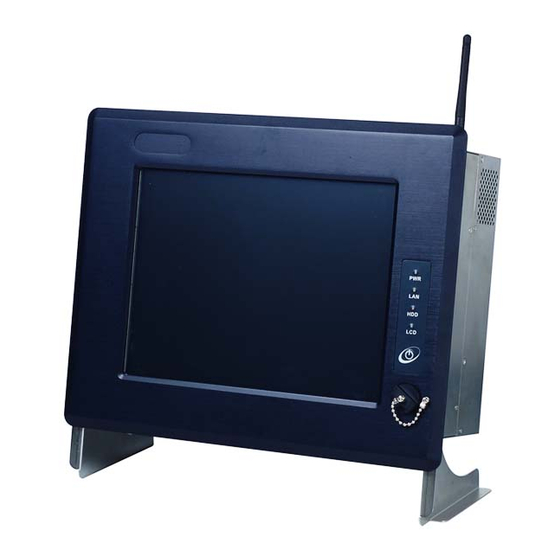
R o b u s t P a n e l P C A P C - 8 1 2 2 Mechanical Drawing AC Input 250W (with Active PFC) ◎Input:115V AC~230V AC @ 47~63Hz ◎Output (Max.): +5V @ 20A, +12V @ 16A, -12V @ 0.5A Operating Temperature 0˚C~50˚C (32˚F~122˚F) Storage Temperature... - Page 19 R o b u s t P a n e l P C A P C - 8 1 2 2 Anti-scratch Front Bezel Status LED and LCD On/Off button USB 1.1 Port with waterproof cover Wireless LAN Kit (Optional) 6 in 1 Card Reader CD-ROM or DVD or Combo...
-
Page 20: Dimension
R o b u s t P a n e l P C A P C - 8 1 2 2 1.4 Dimension 330.00 18.00 18.00 UNIT : mm 149.00 38.00 180.00 9.00 140.00 366.00 8.00 APC-8122 CUTOUT SIZE : 333 x 260 mm 1- 9 Chapter 1 General Information... -
Page 21: Chapter 2 Hardware Installation
R o b u s t P a n e l P C A P C - 8 1 2 2 Chapter Hardware Installation Chapter 2 Hardware Installation... -
Page 22: Safety Precautions
R o b u s t P a n e l P C A P C - 8 1 2 2 2.1 Safety Precautions Always completely disconnect the power cord from your board whenever you are working on it. Do not make connections while the power is on, because a sudden rush of power can damage sensitive electronic components. -
Page 23: Location Of Connectors And Jumpers
R o b u s t P a n e l P C A P C - 8 1 2 2 2.2 Location of Connectors and Jumpers Component Side 2 - 3 Chapter 2 Hardware Installation... -
Page 24: List Of Jumpers
R o b u s t P a n e l P C A P C - 8 1 2 2 2.3 List of Jumpers There are a number of jumpers in the board that allow you to configure your system to suit your application. The table below shows the function of each jumper in the board: Jumpers Label... -
Page 25: List Of Connectors
R o b u s t P a n e l P C A P C - 8 1 2 2 2.4 List of Connectors There are a number of connectors in the board that allow you to configure your system to suit your application. The table below shows the function of each connector in the board: Connectors Label... -
Page 26: Setting Jumpers
R o b u s t P a n e l P C A P C - 8 1 2 2 2.5 Setting Jumpers You configure your card to match the needs of your application by setting jumpers. A jumper is the simplest kind of electric switch. It consists of two metal pins and a small metal clip (often protected by a plastic cover) that slides over the pins to connect them. -
Page 27: Clear Cmos (Jp1)
R o b u s t P a n e l P C A P C - 8 1 2 2 2.6 Clear CMOS (JP1) Warning: To avoid damaging the computer, always turn off the power supply before setting “ Clear CMOS.” Before turning on the power supply, set the jumper back to “Normal.”... -
Page 28: Atx Power Simulate At Power (Jp6)
R o b u s t P a n e l P C A P C - 8 1 2 2 2.10 ATX Power simulate AT Power (JP6) Function 1-2 ON ATX Power Simulate AT Power 1-2 OFF ATX Standard (Default) 2.11 IDE Connector (CN1) Signal Signal... -
Page 29: Fan Connector (Cn8&Cn24)
R o b u s t P a n e l P C A P C - 8 1 2 2 2.12 Fan Connector (CN8&CN24) Signal FAN SPEED SENSE 2.13 10/100Base-TX Ethernet Connector (CN11) Signal Signal 2.14 Option PME Connector (CN12) Signal Signal +5VSB... -
Page 30: Floppy Connector (Cn13)
R o b u s t P a n e l P C A P C - 8 1 2 2 2.15 Floppy Connector (CN13) Signal Signal REDWC INDEX MOTOR A DRIVE SELECT B DRIVE SELECT A MOTOR B STEP WRITE DATA WRITE GATE TRACK... -
Page 31: Com1~4 Rs-232/422/485 Serial Port Connector (Cn16)
R o b u s t P a n e l P C A P C - 8 1 2 2 PTD3 PTD4 PTD5 PTD6 PTD7 BUSY SELECT 2.17 COM1~4 RS-232/422/485 Serial Port Connector (CN16) Only COM 2 support “Wake on Ring” “+5V/+12V” function; COM 4 is reserved for touch screen. -
Page 32: Ps2 Keyboard/Mouse Connector (Cn17)
R o b u s t P a n e l P C A P C - 8 1 2 2 2.18 PS2 Keyboard/Mouse Connector (CN17) Signal KB_DATA KB_CLK MS_DATA MS_CLK 2.19 Digital I/O Port Signal I/O Address Setting Digital-IN / OUT 801H Digital-IN / OUT 801H... - Page 33 R o b u s t P a n e l P C A P C - 8 1 2 2 Digital-IN / OUT 841H Digital-IN / OUT 841H Digital-IN / OUT 841H Digital-IN / OUT 841H Digital-IN / OUT 841H Digital-IN / OUT 841H...
-
Page 34: Vga Display Connector (Cn22)
R o b u s t P a n e l P C A P C - 8 1 2 2 Pin1 Pin2 Pin3 Pin4 Pin7 Pin8 Pin9 Pin10 GPO 27 GPO 26 GPO 25 GPO 24 GPO 23 GPO 22 GPO 21 GPO 20 Address: 841H... -
Page 35: Atx Power Connector (Cn27)
R o b u s t P a n e l P C A P C - 8 1 2 2 2.21 ATX Power Connector (CN27) Signal Signal +3.3V +3.3V +3.3V -12V PS_ON POWER OK +5VSB +12V 2.22 ATX Power 12V Connector (CN28) Signal Signal +12V... -
Page 36: Hdd Installation
R o b u s t P a n e l P C A P C - 8 1 2 2 2.23 HDD Installation In the following, we will guide you how to install HDD. Make sure that all parts are provided before you start the installation. Step 1: Remove the back cover. - Page 37 R o b u s t P a n e l P C A P C - 8 1 2 2 Step 3: Unlock the HDD module. Step 4: Insert the IDE cable into HDD and fix the HDD on the bracket with screws.
- Page 38 R o b u s t P a n e l P C A P C - 8 1 2 2 Step 5: Fix the HDD module with screws as follow. Step 6: Insert the IDE cable on the board. 2 - 18 Chapter 2 Hardware Installation...
-
Page 39: Cd-Rom Installation
R o b u s t P a n e l P C A P C - 8 1 2 2 2.24 CD-ROM Installation After you complete the HDD Installation, we will guide you how to install CD-ROM. Please see the detail as follows. Step 1: Insert CD-ROM cable in the transfer board and plug the transfer board into CD-ROM. - Page 40 R o b u s t P a n e l P C A P C - 8 1 2 2 Step 3: Push the CD-ROM module into the board. Step 4: Plug in CD-ROM Cable as the indicated. 2 - 20 Chapter 2 Hardware Installation...
-
Page 41: Easy Stand Installation
R o b u s t P a n e l P C A P C - 8 1 2 2 2.25 Easy Stand Installation There’re two L-shaped easy stands come with the product. Refer to the following illustration to install it. •... -
Page 42: Panel Mount Kit Installation
R o b u s t P a n e l P C A P C - 8 1 2 2 2.26 Panel Mount Kit Installation Some screw sets will come with the product for user to mount the monitor on the wall. See the steps below along with the illustration. Step 1: Bore the screw into the screw nut. -
Page 43: Waterproof Sponge Installation
R o b u s t P a n e l P C A P C - 8 1 2 2 2.27 Waterproof sponge Installation The following illustration shows you how to lodge the waterproof sponge in the back of the monitor set. Step 1: Lodge the Sponge in the back of the monitor set. -
Page 44: Chapter 3 Bios Installation
R o b u s t P a n e l P C A P C - 8 1 2 2 Chapter BIOS Installation Chapter 3 BIOS Installation 3-1... -
Page 45: System Test And Initialization
R o b u s t P a n e l P C A P C - 8 1 2 2 3.1 System test and initialization These routines test and initialize board hardware. If the routines encounter an error during the tests, you will either hear a few short beeps or see an error message on the screen. -
Page 46: Award Bios Setup
R o b u s t P a n e l P C A P C - 8 1 2 2 information has been erased. The APC-8122 CMOS memory has an integral lithium battery backup for data retention. However, you will need to replace the complete unit when it finally runs down. -
Page 47: Power Management Setup
R o b u s t P a n e l P C A P C - 8 1 2 2 mouse etc.) Power Management Setup Use this menu to specify your settings for power management. (HDD power down, power on by ring, KB wake up, etc.) PnP/PCI Configurations This entry appears if your system supports PnP/PCI. - Page 48 Menu screen. 3.4 Advanced BIOS Features This sample screen contains the manufacturer’s default values for the APC-8122 3.5 Advanced Chipset Features This sample screen contains the manufacturer’s default values for the APC-8122.
- Page 49 R o b u s t P a n e l P C A P C - 8 1 2 2 3.8 PnP/PCI configuration This sample screen contains the manufacturer’s default values for the APC-8122. 3.9 PC Health Status This sample screen contains the manufacturer’s default values for the APC-8122.
-
Page 50: Save & Exit Setup
“disable” front USB port (USB Port 3 controller), the card reader must be forced to disable at same time. For more detailed information, you can refer to the "AAEON BIOS Item Description.pdf" file in the CD for the meaning of each setting in this chapter. - Page 51 R o b u s t P a n e l P C A P C - 8 1 2 2 Chapter Driv Installation 4 - 1 Chapter 4 Driver Installation...
-
Page 52: Realtek Ac97 Codec Driver Installation
R o b u s t P a n e l P C A P C - 8 1 2 2 There are several installation ways depending on the driver package under different Operating System application. The Autorun program will run automatically. However, if the Autorun program cannot be run smoothly, please follow the sequence below to install the drivers: Step 1–... -
Page 53: Intel 845G Graphics Driver Installation
R o b u s t P a n e l P C A P C - 8 1 2 2 4.2 Intel 845G Graphics Driver Installation 1. Click on the Intel 845G Graphics Driver folder and then double click on the win2k_xp14103.exe 2. -
Page 54: Limitations
R o b u s t P a n e l P C A P C - 8 1 2 2 4.4 Realtek AC97 Codec Driver Installation 1.Click on the Realtek AC97 codec Driver folder and then double click on the wdm_a355.exe 2.Follow the instructions the window shows you 3.The system will install the driver automatically 4.5 Card Reader Driver Installation...
Need help?
Do you have a question about the APC-8122 and is the answer not in the manual?
Questions and answers