Table of Contents
Advertisement
Quick Links
Advertisement
Table of Contents

Subscribe to Our Youtube Channel
Related Manuals for IEI Technology SRM-KIT Series


Summary of Contents for IEI Technology SRM-KIT Series
- Page 1 SRM-KIT Series LCD Monitor SRM-KIT LCD Monitor User Manual Page i...
- Page 2 SRM-KIT Series LCD Monitor Revision Title SRM-KIT LCD Monitor User Manual Revision Number Description Date of Issue Initial release January 2007 Page ii...
- Page 3 SRM-KIT Series LCD Monitor Copyright COPYRIGHT NOTICE The information in this document is subject to change without prior notice in order to improve reliability, design and function and does not represent a commitment on the part of the manufacturer. In no event will the manufacturer be liable for direct, indirect, special, incidental, or consequential damages arising out of the use or inability to use the product or documentation, even if advised of the possibility of such damages.
-
Page 4: Packing List
NOTE: If any of the components listed in the checklist below are missing, please do not proceed with the installation. Contact the IEI reseller or vendor you purchased the SRM-KIT from or contact an IEI sales representative directly. To contact an IEI sales representative, please send an email to sales@iei.com.tw. - Page 5 4. Only qualified engineers from certified system integrators or VARs are allowed to make necessary functional modifications to the panel PC, e.g., adding a touch screen. IEI offers the customization service on a pre-order basis. 5. If considerable amount of dust, water, or fluids entered the panel PC, turn off the power supply immediately, unplug the power cord, and contact the vendor.
- Page 6 SRM-KIT Series LCD Monitor operate with the openings obstructed by foreign objects. However, the ambient temperature of the installation site should be observed and controlled to avoid overheating the panel PC. 6. Condensation might form inside the panel PC chassis if exposed to sudden changes in temperature.
- Page 7 SRM-KIT Series LCD Monitor a piece of dry and soft cloth or a slightly moistened cloth with the exterior casing. The interior of the Panel PC does not require cleaning. Keep fluids away from the Panel PC and the interior of it.
- Page 8 SRM-KIT Series LCD Monitor excellent tools for wiping hard to reach areas in the keyboard, mouse, and other locations. F oam swabs - Whenever possible it is better to use lint free swabs such as foam swabs. ESD PRECAUTIONS Observe all conventional anti-ESD methods while handling the components contained within the LCD should the need arise for adding a functionality.
-
Page 9: Table Of Contents
1.1 SRM-KIT S LCD M ............2 ERIES ONITOR VERVIEW 1.1.1 Standard Features ....................2 1.1.2 SRM-KIT Series Industrial Monitor Applications ..........2 1.1.3 Model Variations ....................3 1.2 E ....................3 XTERNAL VERVIEW 1.2.1 Front View ......................3 1.2.2 Rear View ......................4 1.2.3 Connectors ...................... - Page 10 SRM-KIT Series LCD Monitor 3.2 AV-5300 I ............22 NTERNAL ERIPHERAL ONNECTORS 3.2.1 Auto-Dimming Connector ................22 3.2.2 Debug Port Connector..................23 3.2.3 External OSD and LED Indication Connector ..........24 3.2.4 Backlight Inverter Connector ................25 3.2.5 LVDS Output Connector .................. 26 3.2.6 Power Output Connector .................
- Page 11 SRM-KIT Series LCD Monitor 5.1.2 OSD Menu Structure ..................47 5.2 U OSD....................... 48 SING THE 5.2.1 Main Display Features..................48 5.2.2 Color ........................ 50 5.2.3 Image Settings....................51 5.2.4 OSD Configurations..................52 5.2.5 Signal ....................... 53 5.2.6 Auto-Dimming Configurations................. 53 5.2.6.1 Default Settings..................
- Page 12 SRM-KIT Series LCD Monitor List of Figures Figure 1-1: Front View....................3 Figure 1-2: Rear View....................4 Figure 1-3: SRM-KIT Series Connectors ..............5 Figure 1-4: AV-5300 AD Board ..................6 Figure 1-5: SRM-KIT121G Physical Dimensions (millimeters) .........8 Figure 1-6: SRM-KIT150G Physical Dimensions (millimeters) .........9 Figure 1-7: Sizes of Mounting Holes .................10...
- Page 13 SRM-KIT Series LCD Monitor Figure 5-3: Color Options...................50 Figure 5-4: Image Settings Menu................51 Figure 5-5: OSD Configurations Menu ..............52 Figure 5-6: Signal Menu....................53 Figure 5-7: SRM-KIT121G Default Linearity of the LCD Backlight and Ambient Light...................55 Figure 5-8: Auto-Dimming Configurations Menu.............55 Figure 5-9: Decreasing LUX Max.
- Page 14 SRM-KIT Series LCD Monitor List of Tables Table 1-1: SRM-KIT Series Specifications ..............7 Table 2-1: SRM-KIT121G LCD Specifications............13 Table 2-2: SRM-KIT150G LCD Specifications............14 Table 2-3: Power Adapter Specifications..............15 Table 3-1: AV-5300 Peripheral Interface Connectors ..........21 Table 3-2: AV-5300 Rear Panel Connectors .............21 Table 3-3: AV-5300 On-board Jumpers ..............22...
-
Page 15: Introduction
SRM-KIT Series LCD Monitor Chapter Introduction Page 1... -
Page 16: Srm-Kit Series Lcd Monitor Overview
The SRM-KIT series industrial monitor is the latest member of IEI’s line of sophisticated LCD designs, and it has been improved to be RoHS compliant. The SRM-KIT series is designed to fit industrial automation, or any other applications that require minimum installation space and flexible configuration. -
Page 17: Model Variations
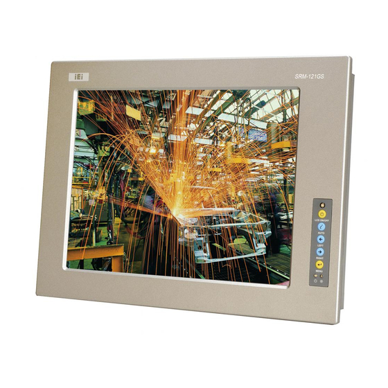
The following sections describe the physical layout of the SRM-KIT series industrial monitors. 1.2.1 Front View The front of the SRM-KIT series monitor is a flat panel TFT LCD screen attached to a metal chassis. Figure 1-1 shows a typical SRM-KIT front view. Figure 1-1: Front View... -
Page 18: Rear View
SRM-KIT Series LCD Monitor 1.2.2 Rear View The rear of the SRM-KIT series monitor is a metal chassis. An on screen display (OSD) control button panel is located vertically on the left side of the chassis with the following control buttons:... -
Page 19: Connectors
CPU card through cabling. Figure 1-4 shows the AV-5300 AD board as a sample of a typical AD board for the SRM-KIT series monitor. Refer to Chapter 3 for a complete description of AD boards and their connectors. -
Page 20: Series Specifications
SRM-KIT Series LCD Monitor Figure 1-4: AV-5300 AD Board 1.4 Series Specifications Table 1-1 shows the SRM-KIT Series specifications. Model SRM-KIT121G SRM-KIT150G 12.1” 15” LCD Size Analog VGA and DVI-D Input Interface 800 x 600 1024 x 768 Resolution 1000 cd/m... -
Page 21: Certification
Operation Temperature -20°C~80°C Storage Temperature Table 1-1: SRM-KIT Series Specifications 1.5 Certification All SRM-KIT series industrial monitor models comply with the following international standard: RoHS For a more detailed description of the standard, please refer to Sections A.1. Page 7... -
Page 22: Physical Dimensions
SRM-KIT Series LCD Monitor 1.6 Physical Dimensions The following sections describe the physical dimensions for the SRM-KIT121GS and SRM-KIT150G industrial monitor. 1.6.1 SRM-KIT121G Physical Dimensions The physical dimensions of the SRM-KIT121G are shown in Figure 1-5. Figure 1-5: SRM-KIT121G Physical Dimensions (millimeters) -
Page 23: Srm-Kit150G Physical Dimensions
SRM-KIT Series LCD Monitor 1.6.2 SRM-KIT150G Physical Dimensions The physical dimensions of the SRM-KIT150G are shown in Figure 1-6. Figure 1-6: SRM-KIT150G Physical Dimensions (millimeters) Page 9... -
Page 24: Mounting Options
SRM-KIT Series LCD Monitor 1.7 Mounting Options Each SRM-KIT series monitor has mounting holes located on the mounting bracket and the rear panel. The mounting holes on the mounting bracket are for panel mounting. Figure 1-7 shows the sizes of the holes on the mounting bracket. -
Page 25: Lcd Specifications
SRM-KIT Series LCD Monitor Chapter LCD Specifications Page 11... -
Page 26: Lcd Specifications
SRM-KIT Series LCD Monitor 2.1 LCD Specifications 2.1.1 LCD Overview The SRM-KIT series industrial monitors use the following LCD panels. SRM-KIT121G: MITSUBISHI AA121SN02 SVGA TFT LCD SRM-KIT150G: MITSUBISHI AA150XN08 XGA TFT LCD Detailed specifications for the LCD screens are listed in the following sections. -
Page 27: Srm-Kit150G Lcd Specifications
SRM-KIT Series LCD Monitor 3.3V / 3.6V (Max.) Power Supply Voltage for LCD 300mA / 450mA Power Supply Current for LCD Voltage: 540 Vrms Lamp Voltage/Current Current: 12.0 mArms/14.0 mAms (Max.) 1000 Vrms (25°C)/ 1200 Vrms (0°C)/ Starting Lamp Minimum Voltage 1290 Vrms (-20°C) -
Page 28: Table 2-2: Srm-Kit150G Lcd Specifications
SRM-KIT Series LCD Monitor 150 / 110 View Angle (H/V) Brightness (cd/m2) 600:1 Contrast Ratio : 6 T : 19 Response Time (ms) LVDS (6 bit/8 bit) Interface 3.3V Input Voltage (V) 4 CCFL Backlight 3.3V / 3.6V (Max.) Power Supply Voltage for LCD... -
Page 29: Power Adapters
SRM-KIT Series LCD Monitor 2.2 Power Adapters Table 2-3 lists the AC/DC power adapter specifications. 45 Watt AC/DC Adapter Power Universal Input 90 to 264 VAC General Description EMI Meets FCC/CISPR 22 Class B MTBF 165Khrs Limited Power Source 90-264VAC... - Page 30 SRM-KIT Series LCD Monitor THIS PAGE IS INTENTIONALLY LEFT BLANK Page 16...
-
Page 31: Ad Board
SRM-KIT Series LCD Monitor Chapter AD Board Page 17... -
Page 32: Av-5300 Ad Board Overview
SRM-KIT Series LCD Monitor 3.1 AV-5300 AD Board Overview The SRM series industrial monitor AD board provides a wide variety of control interfaces, receiving and managing interface signals from a CPU card through cabling. The following sections describe the AV-5300 AD board in detail. -
Page 33: Av-5300 Ad Board Connectors
SRM-KIT Series LCD Monitor 3.1.1 AV-5300 AD Board Connectors The AV-5300 AD board has the following connectors on-board: 1 x Auto-dimming connector 1 x Debug connector 1 x External OSD and LED Indication connector 1 x Inverter interface connector 1 x LVDS connector... -
Page 34: Av-5300 Ad Board Layout
SRM-KIT Series LCD Monitor 3.1.2 AV-5300 AD Board Layout Figure 3-2 shows the on-board peripheral connectors and on-board jumpers. Figure 3-2: Connector and Jumper Locations Page 20... -
Page 35: Av-5300 Peripheral Interface Connectors
SRM-KIT Series LCD Monitor 3.1.3 AV-5300 Peripheral Interface Connectors Table 3-1 shows a list of the peripheral interface connectors on the AV-5300 AD board. Detailed descriptions of these connectors can be found in Section 3.2. Connector Type Label Auto-dimming connector... -
Page 36: Av-5300 On-Board Jumpers
SRM-KIT Series LCD Monitor 3.1.5 AV-5300 On-board Jumpers Table 3-3 lists the on-board jumpers. A detailed description of these jumpers can be found in Section 3.3. Jumper Type Label LCD Panel Power Input Select 6-pin header LCD Panel Voltage Select... -
Page 37: Debug Port Connector
SRM-KIT Series LCD Monitor Table 3-4: Auto-dimming Connector Pinouts Figure 3-3: Auto-dimming Connector Location 3.2.2 Debug Port Connector CN Label: CN Type: 4-pin wafer connector CN Pinouts: See Table 3-5 CN Location: See Figure 3-4 Use the debug port connector to update the AD board BIOS. -
Page 38: External Osd And Led Indication Connector
SRM-KIT Series LCD Monitor Figure 3-4: Debug Port Connector Location 3.2.3 External OSD and LED Indication Connector CN Label: CN Type: 9-pin wafer connector CN Pinouts: See Table 3-6 CN Location: See Figure 3-5 The External OSD and LED Indication connector connects to an external OSD controller. -
Page 39: Backlight Inverter Connector
SRM-KIT Series LCD Monitor Figure 3-5: External OSD and LED Indication Connector Location 3.2.4 Backlight Inverter Connector CN Label: CN Type: 6-pin wafer connector CN Pinouts: See Table 3-7 CN Location: See Figure 3-6 The Inverter connector connects to the LCD backlight. Using the BKLT_EN signal to control the inverter status (ON/OFF) and the BKLT_ADJ signal to adjust brightness of inverter by OSD brightness function. -
Page 40: Lvds Output Connector
SRM-KIT Series LCD Monitor Figure 3-6: Backlight Inverter Connector Location 3.2.5 LVDS Output Connector CN Label: CN Type: 30-pin connector CN Pinouts: See Table 3-8 CN Location: See Figure 3-7 Use either LVDS output connector to connect the LCD panel to a system. -
Page 41: Power Output Connector
SRM-KIT Series LCD Monitor TXE0+ TXE0- Table 3-8: LVDS Output Connector Pinouts Figure 3-7: LVDS Output Connector Location NOTE: The supply voltage (3.3V (Default), 5V or 12V) can be selected via JP1. 3.2.6 Power Output Connector CN Label: CN12, CN13... -
Page 42: Power Input Connector
SRM-KIT Series LCD Monitor DESCRIPTION +12V Table 3-9: Power Output Connector Pinouts (CN12) DESCRIPTION Table 3-10: Power Output Connector Pinouts (CN13) Figure 3-8: Power Output Connector Locations 3.2.7 Power Input Connector CN Label: CN24, CN25 CN Type: 2-pin wafer connector, 3-pin wafer connector... -
Page 43: Vga Connector
SRM-KIT Series LCD Monitor The AV-5300 supports two internal power input connectors. DESCRIPTION +12V Table 3-11: Power Input Connector Pinouts (CN24) DESCRIPTION +12V Input +24V to external power module Table 3-12: Power Input Connector Pinouts (CN25) Figure 3-9: Power Input Connector Locations 3.2.8 VGA Connector... -
Page 44: Figure 3-10: Vga Connector Location
SRM-KIT Series LCD Monitor CN Location: See Figure 3-10 In addition to the standard DB-15 female VGA connector (J1), a VGA connection can also be made through the on-board CN2 10-pin header. DESCRIPTION DESCRIPTION SMCLK GREEN SMDATA BLUE GROUND HSYNC... -
Page 45: Av-5300 On-Board Jumpers
SRM-KIT Series LCD Monitor 3.3 AV-5300 On-board Jumpers NOTE: A jumper is a metal bridge used to close an electrical circuit. It consists of two or three metal pins and a small metal clip (often protected by a plastic cover) that slides over the pins to connect them. -
Page 46: Lcd Panel Power Input Jumper
SRM-KIT Series LCD Monitor 3.3.1 LCD Panel Power Input Jumper Jumper Label: Jumper Type: 6-pin header Jumper Location: See Figure 3-12 Jumper Settings: See Table 3-14 The JP4 jumper sets the input source from either the 12V power connector (J3) or the external terminal block. -
Page 47: Av-5300 External (Rear Panel) Connectors
SRM-KIT Series LCD Monitor 3.4 AV-5300 External (Rear Panel) Connectors Figure 3-13 shows the AV-5300 external (rear panel) connectors. The peripheral connectors on the back panel of the monitor can connect to external devices. The peripheral connectors on the rear panel are:... -
Page 48: Vga Connector
SRM-KIT Series LCD Monitor 3.4.2 VGA Connector CN Label: CN Type: D-sub 15 female connector CN Pinouts: See Table 3-17 and Figure 3-14 CN Location: See Figure 3-13 Use the standard D-sub 15-pin VGA connector to connect the monitor to a system. -
Page 49: Figure 3-15: Dvi-D Connector Pinout Locations
SRM-KIT Series LCD Monitor CN Location: See Figure 3-13 The 24-pin female dual link digital only DVI [Digital Visual Interface] connector is a standard for high-speed, high-resolution digital displays. Use the DVI-D connector to connect the LCD to a system. - Page 50 SRM-KIT Series LCD Monitor THIS PAGE IS INTENTIONALLY LEFT BLANK Page 36...
-
Page 51: Installation
SRM-KIT Series LCD Monitor Chapter Installation Page 37... -
Page 52: Installation Precautions
SRM-KIT Series LCD Monitor 4.1 Installation Precautions When installing the SRM-KIT series industrial monitor, please follow the precautions listed below: Read the user manual: The user manual provides a complete description of the SRM-KIT series industrial monitor, installation instructions and configuration options. -
Page 53: Unpacking
4.2 Unpacking 4.2.1 Packaging When shipped, the SRM-KIT series industrial monitor is wrapped in a plastic bag. Two polystyrene ends are placed on either side of the monitor. The monitor is then placed into a first (internal) cardboard box. This box is then sealed and placed into a second (external) cardboard box. -
Page 54: Packing List
SRM-KIT Series LCD Monitor 4.2.3 Packing List All the monitors in the SRM-KIT series are shipped with the following components: Quantity Item Image 45W AC power adapter AC power cord DVI cable Screw kit VGA cable User manual and driver CD If any of these items are missing or damaged, contact the distributor or sales representative immediately. -
Page 55: Voltage Select Jumper Settings
Use the jumper(s) to set the correct voltage input. (See Section 3.3.2) Replace Step 4: the rear panel. Replace all removed screws.Step 0: Step 5: 4.4 Connectors Table 4-1 lists the external peripheral interface panel connectors for the SRM-KIT series industrial monitors. Page 41... -
Page 56: Vga Connector
SRM-KIT Series LCD Monitor SRM-KIT121G SRM-KIT150G DVI-D Power (12V Jack) Table 4-1: External Peripheral Interface Connectors 4.4.1 VGA Connector Use the rear panel standard 15-pin female VGA connector to connect the monitor to the system graphics interface. DESCRIPTION DESCRIPTION No Connect... -
Page 57: Power Connector
SRM-KIT Series LCD Monitor DESCRIPTION DESCRIPTION DESCRIPTION TMDS Data2- TMDS Data1- TMDS Data0- TMDS Data2+ TMDS Data1+ TMDSData0+ TMDS Data2/4 Shield TMDS Data1/3 Shield TMDS Data0/5 Shield TMDS Data4- TMDS Data3- TMDS Data5- TMDS Data4+ TMDS Data3+ TMDS Data5+ DDC Clock [SCL]... -
Page 58: Mounting The Srm-Kit Series Lcd Monitor
SRM-KIT Series LCD Monitor 4.5 Mounting the SRM-KIT Series LCD Monitor Each SRM-KIT series monitor comes with a preinstalled mounting bracket with a number of holes available for mounting purposes that system integrators will find especially useful. Refer to Sections 1.7 for further details on the number and location of mounting holes for each model of the SRM-KIT series monitor. -
Page 59: On-Screen-Display (Osd) Controls
SRM-KIT Series LCD Monitor Chapter On-Screen-Display (OSD) Controls Page 45... -
Page 60: User Mode Osd Structure
SRM-KIT Series LCD Monitor 5.1 User Mode OSD Structure 5.1.1 OSD Buttons There are several on-screen-display (OSD) control buttons oriented vertically and temporarily along the right hand side of the monitor rear panel. The user can reposition the OSD panel to fit their needs. To make the auto-dimming function properly, please install the OSD panel at a place where no obstacle blocks ambient light sensor. -
Page 61: Osd Menu Structure
The power LED is turned on in green when the LCD monitor is on. Auto-dimming LED The auto-dimming LED is turned on in red when the auto-dimming function is 5.1.2 OSD Menu Structure Table 5-1 shows the OSD menu structure for all models of the SRM-KIT series LCD monitor. Level 0 Level 1... -
Page 62: Using The Osd
SRM-KIT Series LCD Monitor 6500K - Preset NTSC value User Temp RGB values from 0 to 100 Image Setting Menu Auto Color Select Width 0 to 100 Phase 0 to 100 H. Position 0 to 100 V. Position 0 to 100... -
Page 63: Figure 5-2: Main Display Features
SRM-KIT Series LCD Monitor Figure 5-2: Main Display Features The brightness option adjusts the brightness of screen. This function adjusts the offset value of ADC. Setting this value too high or too low will affect the quality of image. When the auto-... -
Page 64: Color
SRM-KIT Series LCD Monitor 5.2.2 Color Color options are shown in Figure 5-3. Figure 5-3: Color Options The Color menu fine-tunes the palette of color hues for the LCD. NTSC standard Kelvin 9300k NTSC standard Kelvin 7500k NTSC standard Kelvin... -
Page 65: Image Settings
SRM-KIT Series LCD Monitor 5.2.3 Image Settings The image settings are shown in Figure 5-4. Figure 5-4: Image Settings Menu Image settings are described below. Automatically adjusts the color settings. Auto Color Adjusts the width of the display screen. Width... -
Page 66: Osd Configurations
SRM-KIT Series LCD Monitor 5.2.4 OSD Configurations The OSD configurations are shown in Figure 5-5. Figure 5-5: OSD Configurations Menu OSD Configurations are described below. Determines how many seconds the OSD screen stays on OSD Time Out screen before it disappears when OSD is left unattended. -
Page 67: Signal
SRM-KIT Series LCD Monitor 5.2.5 Signal The Signal menu in Figure 5-6 enables manual selection of the type of graphic source input: 15-pin VGA Analog DVI-D Digital Figure 5-6: Signal Menu 5.2.6 Auto-Dimming Configurations The SRM-KIT industrial monitor features an auto-dimming LCD that can automatically adjust the backlight brightness according to the ambient light. -
Page 68: Default Settings
The Figure 5-7 shows the SRM-KIT121G default linearity of the LCD backlight and ambient light. When the sensor detects the ambient illuminance as 5200 LUX or above, the SRM-KIT series industrial monitor adjusts the LCD brightness to 100%. Page 54... -
Page 69: Osd Control
SRM-KIT Series LCD Monitor 1000 100%100% 100% 100% 100% 100% Ambient Light (LUX) Figure 5-7: SRM-KIT121G Default Linearity of the LCD Backlight and Ambient Light 5.2.6.2 OSD Control The auto-dimming configurations are shown in Figure 5-5. Figure 5-8: Auto-Dimming Configurations Menu Auto-Dimming Configurations are described below. -
Page 70: Changing The Default Settings
SRM-KIT Series LCD Monitor Turn on or turn off auto-dimming function. When auto-dimming is turned on, the auto-dimming LED on the OSD panel is on Light Enable and the monitor automatically adjusts the brightness according ON/OFF to ambient light conditions. -
Page 71: Figure 5-9: Decreasing Lux Max. Value
LUX Max. and LUX Min. The SRM-KIT series is an ideal product for outdoor display. However, if the SRM-KIT series is installed in an environment with stable and low lux lighting, the LCD monitor cannot detect the default maximum lux (5200 lux) and make the LCD brightness reach to the maximum. -
Page 72: Figure 5-10: Light Max, Light Min And Lux Min In Default Value
SRM-KIT Series LCD Monitor Keep Light Max. in default setting: 100 Keep Light Min. in default setting: 0 Keep LUX Min. in default setting: 0 Figure 5-10: Light Max, Light Min and LUX Min in Default Value Page 58... -
Page 73: Acertification
SRM-KIT Series LCD Monitor Appendix Certification Page 59... -
Page 74: Rohs Compliant
SRM-KIT Series LCD Monitor A.1 RoHS Compliant All models in the SRM-KIT LCD monitor series comply with the Restriction of Hazardous Materials (RoHS) Directive. This means that all components used to build the industrial workstations and the workstation itself are RoHS compliant. -
Page 75: Bindex
SRM-KIT Series LCD Monitor Index Page 61... - Page 76 SRM-KIT Series LCD Monitor Light Max, 62, 70 Light Min, 62, 70 LUX Max, 62, 70 12V, 33, 35, 41, 46, 47 LUX Min, 62, 70 AD board, 32, 33, 35, 36 Model Variations, 17 AD Board, 32, 33, 34, 50...
- Page 77 SRM-KIT Series LCD Monitor Dimension, 21 Display Color, 21 terminal block, 46 Input Interface, 20 touch screen, 5 Input Voltage, 21 LCD Size, 20 Mounting, 21 Operation Temperature, 21 USB, 16 OSD Function, 21 Pixel Pitch, 21 Resolution, 20 VESA, 24...
Need help?
Do you have a question about the SRM-KIT Series and is the answer not in the manual?
Questions and answers