
Subscribe to Our Youtube Channel
Related Manuals for IEI Technology DM series


Summary of Contents for IEI Technology DM series
-
Page 1: User Manual
DM Series Monitor DM Series Industrial Monitor IEI Technology Corp. MODEL: DM Series 6.5”~19” LCD Monitor IP 65 Protection, VGA/DVI-D, 9-36V Input User Manual Page I Rev. 2.04 – 5 May, 2011... - Page 2 DM Series Monitor Revision Date Version Changes 5 May, 2011 2.04 Added panel opening dimensions in Section 5.5.1 23 February, 2011 2.03 Minor changes 29 December, 2010 2.02 Updated Chapter 7 Software Drivers 09 December, 2010 2.01 Modified AV-6600 AD board information.
- Page 3 DM Series Monitor Copyright COPYRIGHT NOTICE The information in this document is subject to change without prior notice in order to improve reliability, design and function and does not represent a commitment on the part of the manufacturer. In no event will the manufacturer be liable for direct, indirect, special, incidental, or consequential damages arising out of the use or inability to use the product or documentation, even if advised of the possibility of such damages.
-
Page 4: Table Of Contents
DM Series Monitor Table of Contents 1 INTRODUCTION......................1 1.1 O ........................2 VERVIEW 1.2 F ........................2 EATURES 1.3 M ....................3 ODEL ARIATIONS 1.4 A ......................4 PPLICATIONS 1.5 E ....................4 XTERNAL VERVIEW 1.5.1 Front View ......................5 1.5.2 Bottom Panel View ..................... - Page 5 DM Series Monitor 2.4.3 DM-170 Physical Dimensions ................. 19 2.4.4 DM-150 Physical Dimensions ................. 20 2.4.5 DM-121 Physical Dimensions ................. 21 2.4.6 DM-104 Physical Dimensions ................. 22 2.4.7 DM-84 Physical Dimensions ................23 2.4.8 DM-65 Physical Dimensions ................24 2.5 O ..................
- Page 6 DM Series Monitor 4.4.1 AV-6600 Peripheral Interface Connectors............43 4.4.2 AV-6600 Rear Panel Connectors ..............44 5 INSTALLATION......................45 5.1 I ................... 46 NSTALLATION RECAUTIONS 5.2 U ......................47 NPACKING 5.2.1 Packaging ......................47 5.2.2 Unpacking Procedure ..................47 5.2.3 Packing List ..................... 48 5.3 P...
- Page 7 DM Series Monitor 6.1.1 OSD Buttons..................... 75 6.1.2 OSD Menu Structure ..................76 6.2 U OSD....................... 78 SING THE 6.2.1 Main Display Features..................78 6.2.2 Color ........................ 79 6.2.3 OSD Configurations..................80 7 SOFTWARE DRIVERS....................81 7.1 I ......................82 NTRODUCTION 7.2 RS-232...
- Page 8 DM Series Monitor C.4.3 Image Page....................106 C.4.4 Display Page (for analog signal) ..............107 C.4.5 Color Page ....................108 C.4.6 PIP Page......................109 C.4.7 System Page....................110 C.4.8 About Page ..................... 111 OSD FAQ ....................112 SMART C.5.1 Windows 2000 Installation Failure ..............112 C.5.2 Vista Installation Failure................112...
- Page 9 DM Series Monitor List of Figures Figure 1 1: DM Series ........................2 Figure 1-2: Typical Monitor Front View ..................5 Figure 1-3: DM-190 Bottom Panel View ..................6 Figure 1-4: AV-6600 AD Board ......................7 Figure 2-1: Front Panel Variant 1 ....................12 Figure 2-2: Front Panel Variant 2 ....................13 Figure 2-3: Front Panel Variant 3 ....................14...
- Page 10 DM Series Monitor Figure 5-14: Insert the Monitor....................59 Figure 5-15: Panel Mounting Clamp Position ................59 Figure 5-16: DM-65 Panel Opening (Unit: mm) ................60 Figure 5-17: DM-65 Panel Mounting....................61 Figure 5-18: Secure the Cabinet/Rack Bracket................63 Figure 5-19: Install into a Cabinet/Rack ..................64 Figure 5-20: Rack Mounting Nuts and Bolts Installation (DM-190) .........65...
- Page 11 DM Series Monitor Figure 8-1: Gasket Replacement....................90 Figure 8-2: smartOSD Installer....................99 Figure 8-3: smartOSD Welcome Screen..................99 Figure 8-4: smartOSD Folder Select Screen................100 Figure 8-5: smartOSD Confirm Installation................100 Figure 8-6: smartOSD Installation Progress................101 Figure 8-7: smartOSD Installation Complete ................101 Figure 8-8: Manage Page ......................
- Page 12 DM Series Monitor List of Tables Table 1-1: DM Series Model Variations..................3 Table 1-2: DM Series Specifications .....................9 Table 2-1: Front Panel Variants....................11 Table 2-2: General Physical Dimensions ...................17 Table 2-3: DM-65 Mounting Kits ....................25 Table 2-4: DM-84 Mounting Kits ....................26 Table 2-5: DM-104 Mounting Kits ....................26...
- Page 13 DM Series Monitor Table C-1: SmartOSD Menu Structure..................103 Page XIII...
-
Page 15: Introduction
DM Series Monitor Chapter Introduction Page 1... -
Page 16: Overview
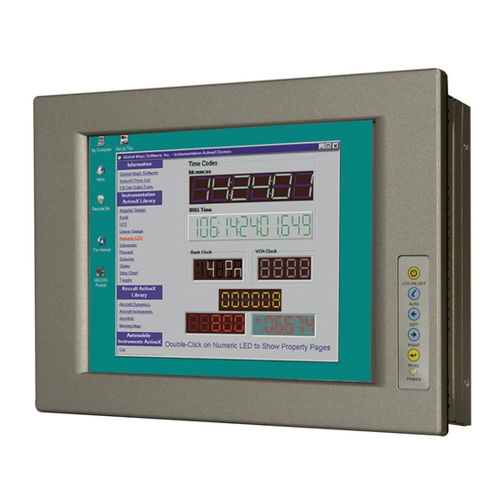
1.1 Overview Figure 1 1: DM Series The DM series LCD monitor is the latest member of IEI’s line of sophisticated LCD designs, and it has been improved to be RoHS compliant. It is designed to fit industrial automation, or any other applications that require minimum installation space and flexible configuration. -
Page 17: Model Variations
DM-190: 19” LCD screen The DM series LCD monitor base models may or may not have a variety of variants. The standard model name is DM-(XX/XXX), where (XX/XXX) refers to either the two or three digit size of the monitor. The model variations are listed in T able 1-1. -
Page 18: Applications
Video rental kiosk Self-service POS terminal 1.5 External Overview The DM series LCD monitors are durable devices that can be used in harsh industrial environments. The following sections describe the physical layout of the DM series LCD monitors. Page 4... -
Page 19: Front View
DM Series Monitor 1.5.1 Front View The front of the DM series LCD monitor is a flat panel LCD screen surrounded by an aluminum frame. A control button panel (OSD), if available, is located either vertically on the right side of the frame or horizontally along the bottom of the frame with the following... -
Page 20: Bottom Panel View
DM Series Monitor 1.5.2 Bottom Panel View F igure 1-3 shows the bottom panel of the DM-190 monitor. Other models may include or exclude additional connectors. Refer to Section 2 .3 for listings of monitors and their connectors. All connectors are fully described in Section 5 .4. -
Page 21: Ad Board
CPU card through cabling. F igure 1-4 shows the AV-6600 AD board as a sample of a typical AD board for the DM series LCD monitor. Refer to Chapter 4 for a complete description of AD boards and their connectors. -
Page 22: Series Specifications
DM Series Monitor 1.6 Series Specifications T able 1-2 shows the DM Series specifications. Model DM-65 DM-84 DM-104 DM-121 DM-150 DM-170 DM-190 LCD Size 6.5” 8.4” 10.4” 12.1” 15” 17” 19” Input Interface DVI-D DVI-D DVI-D DVI-D Max. 640x480 800x600... -
Page 23: Certifications
1.8kg 3.8kg 8.6kg 10kg Table 1-2: DM Series Specifications 1.7 Certifications All DM series LCD monitor models comply with the following international standards: RoHS IP 65 For a more detailed description of these standards, please refer to Appendix Page 9... -
Page 24: Mechanical Overview
DM Series Monitor Chapter Mechanical Overview Page 10... -
Page 25: Introduction
2.2 Front Panel The front panel of the DM series LCD monitor is comprised of a LCD in an aluminum frame with an OSD control panel. 2.2.1 Front Panel Variants T able 2-1 shows the three front panel variants for the DM series LCD monitor. -
Page 26: Front Panel Variant 1
DM Series Monitor 2.2.2 Front Panel Variant 1 The following models of the DM series LCD monitor have an OSD control panel located vertically along the right side of the aluminum frame: DM-170 DM-150 DM-121 DM-104 DM-84 F igure 2-1 shows the location of the front panel variant 1 OSD controls. -
Page 27: Front Panel Variant 2
DM Series Monitor 2.2.3 Front Panel Variant 2 The following model of the DM series LCD monitor has an OSD control panel located horizontally along the bottom of the aluminum frame: DM-190 F igure 2-2 shows the location of the front panel variant 2 OSD controls. -
Page 28: Front Panel Variant 3
DM Series Monitor 2.2.4 Front Panel Variant 3 The following model of the DM series LCD monitor has an OSD control panel located in-line along the bottom of the aluminum frame: DM-65 F igure 2-3 shows the location of the front panel variant 3 OSD controls. -
Page 29: Connectors
DM Series Monitor 2.3.2 DM-65 Connectors The following is a list of the bottom panel peripheral device connectors used on the DM-65 series LCD monitor. VGA connector 12V power connector USB connector for touchscreen 2.3.3 DM-84 Connectors The following is a list of the bottom panel peripheral device connectors used on the DM-84 series LCD monitor. -
Page 30: Connectors
DM Series Monitor USB connector for touchscreen 9~36V terminal block (M model only) 2.3.6 DM-150 Connectors The following is a list of the bottom panel peripheral device connectors used on the DM-150 series LCD monitor. VGA connector DVI-D connector 12V power connector... -
Page 31: Physical Dimensions
DM Series Monitor 2.4 Physical Dimensions The following sections describe the physical dimensions for each model of the DM series LCD monitor. 2.4.1 General Physical Dimensions General physical dimensions for the DM series LCD monitors are shown in T able 2-2. -
Page 32: Physical Dimensions
DM Series Monitor 2.4.2 DM-190 Physical Dimensions The physical dimensions of the DM-190 are shown in F igure 2-4. Figure 2-4: DM-190 Physical Dimensions (millimeters) Page 18... -
Page 33: Figure 2-5: Dm-170 Physical Dimensions (Millimeters)
DM Series Monitor 2.4.3 DM-170 Physical Dimensions The physical dimensions of the DM-170 are shown in F igure 2-5. Figure 2-5: DM-170 Physical Dimensions (millimeters) Page 19... -
Page 34: Physical Dimensions
DM Series Monitor 2.4.4 DM-150 Physical Dimensions The physical dimensions of the DM-150 are shown in F igure 2-6. Figure 2-6: DM-150 Physical Dimensions (millimeters) Page 20... -
Page 35: Physical Dimensions
DM Series Monitor 2.4.5 DM-121 Physical Dimensions The physical dimensions of the DM-121 are shown in F igure 2-7. Figure 2-7: DM-121 Physical Dimensions (millimeters) Page 21... -
Page 36: Physical Dimensions
DM Series Monitor 2.4.6 DM-104 Physical Dimensions The physical dimensions of the DM-104 are shown in F igure 2-8. Figure 2-8: DM-104 Physical Dimensions (millimeters) Page 22... -
Page 37: Physical Dimensions
DM Series Monitor 2.4.7 DM-84 Physical Dimensions The physical dimensions of the DM-84 are shown in F igure 2-9. Figure 2-9: DM-84 Physical Dimensions (millimeters) Page 23... -
Page 38: Physical Dimensions
DM Series Monitor 2.4.8 DM-65 Physical Dimensions The physical dimensions of the DM-65 are shown in F igure 2-10. Figure 2-10: DM-65 Physical Dimensions (millimeters) Page 24... -
Page 39: Optional Mounting Kits
DM Series Monitor 2.5 Optional Mounting Kits The following sections describe the various optional mounting kits available for each model of the DM series LCD monitor. Refer to Section 5.5 for detailed instructions on the different mounting methods for the monitors. CAUTION: Due to safety concerns, it is highly recommended to use the VESA mounting kits provided by IEI for wall, stand and arm mounting. -
Page 40: Mounting Kits
DM Series Monitor LCD Monitor Arm ARM-11 LCD Monitor Stand STAND-100-RS Table 2-4: DM-84 Mounting Kits 2.5.3 DM-104 Mounting Kits T able 2-5 lists the mounting kits available for the DM-104 monitor. Model DM-104 Panel Mounting Kit PK-104M Rack Mounting Kit... -
Page 41: Mounting Kits
DM Series Monitor 2.5.5 DM-150 Mounting Kits T able 2-7 lists the mounting kits available for the DM-150 monitor. Model DM-150 Panel Mounting Kit PK-150M Rack Mounting Kit RK-150MS-R10 Wall Mounting Kit WK-150MS-R10 DIN Mounting Kit LCD Monitor Arm ARM-31... -
Page 42: Mounting Kits
DM Series Monitor 2.5.7 DM-190 Mounting Kits T able 2-9 lists the mounting kits available for the DM-190 monitor. Model DM-190 Panel Mounting Kit PK-190M Rack Mounting Kit RK-190MS-R10 Wall Mounting Kit WK-190MS-R10 DIN Mounting Kit LCD Monitor Arm ARM-31... -
Page 43: Lcd Specifications
DM Series Monitor Chapter LCD Specifications Page 29... -
Page 44: Lcd Specifications
DM Series Monitor 3.1 LCD Specifications 3.1.1 LCD Overview The DM series LCD monitors use the following LCD panels. HANNSTAR/HSD190MEN3-A DM-190: AUO G170EG01 V0 DM-170: AUO G150XG01 V1 DM-150: AUO G121XN01 V0 DM-121: AUO/G104SN02 V2 DM-104: AUO/G084SN05 V8 DM-084: AUO/G065VN01 V2 DM-65: Detailed specifications for the LCD screens are listed in the following sections. -
Page 45: Lcd Specifications
DM Series Monitor 3.1.2 DM-190 LCD Specifications T able 3-1 lists the DM-190 LCD specifications. Model DM-190 Size 19” MFR/Model HANNSTAR/HSD190MEN3-A Resolution SXGA (1280 x 1024) Active Area (mm) 376.32 x 301.06 Pixel Pitch (mm) 0.294 Mode Number of Colors 16.7M... -
Page 46: Lcd Specifications
DM Series Monitor 3.1.3 DM-170 LCD Specifications T able 3-2 lists the DM-170 LCD specifications. Model DM-170 Size 17” MFR/Model AUO/G170EG01 V0 Resolution SXGA (1280 x 1024) Active Area (mm) 337.9 x 270.3 Pixel Pitch (mm) 0.264 Mode Number of Colors 16.7M... -
Page 47: Lcd Specifications
DM Series Monitor 3.1.4 DM-150 LCD Specifications T able 3-3 lists the DM-150 LCD specifications. Model DM-150 Size 15” MFR/Model AUO/G150XG01 V1 Resolution XGA (1024 x 768) Active Area (mm) 304.1 x 228.1 Pixel Pitch (mm) 0.297 Mode Number of Colors 16.2M... -
Page 48: Lcd Specifications
DM Series Monitor 3.1.5 DM-121 LCD Specifications T able 3-4 lists the DM-121 LCD specifications. Model DM-121 Size 12.1” MFR/Model AUO/G121XN01 V0 Resolution XGA (1024 x 768) Active Area (mm) 245.76 x 184.32 Pixel Pitch (mm) 0.3075 Mode Number of Colors... -
Page 49: Lcd Specifications
DM Series Monitor 3.1.6 DM-104 LCD Specifications T able 3-5 lists the DM-104 LCD specifications. Model DM-104 10.4” Size AUO/G104SN02 V2 MFR/Model SVGA (800 x 600) Resolution 211.2 x 158.4 Active Area (mm) 0.264 Pixel Pitch (mm) Mode 262K Number of Colors... -
Page 50: Lcd Specifications
DM Series Monitor 3.1.7 DM-84 LCD Specifications T able 3-6 lists the DM-84 LCD specifications. Model DM-84 Size 8.4” AUO/G084SN05 V8 MFR/Model SVGA (800 x 600) Resolution 170.4 x 127.8 Active Area (mm) 0.213 Pixel Pitch (mm) Mode 262K Number of Colors... -
Page 51: Lcd Specifications
DM Series Monitor 3.1.8 DM-65 LCD Specifications T able 3-7 lists the DM-65 LCD specifications. Model DM-65 Size 6.5” MFR/Model AUO/G065VN01 V2 Resolution VGA (640 x 480) Active Area (mm) 132.48 x 99.36 Pixel Pitch (mm) 0.207 Mode Number of Colors... -
Page 52: Ad Boards
DM Series Monitor Chapter AD Boards Page 38... -
Page 53: Ad Board Overview
CPU card through cabling. There are three AD boards used for the DM series monitors: AV-9650, AV-6650 and AV-6600. Refer T able 1-2 for a listing of DM series monitors and their associated AD board. The following sections describe each AD board in detail. -
Page 54: Av-9650 Rear Panel Connectors
DM Series Monitor Connector Type Label Auto-dimming connector 6-pin wafer connector Backlight Inverter connector 4-pin wafer connector CN16 Debug port connector 4-pin wafer connector External OSD and 9-pin wafer connector CN10 LED indication connector LVDS connector 30-pin crimp connector CN15... -
Page 55: Av-6650 Ad Board Overview
DM Series Monitor 4.3 AV-6650 AD Board Overview Figure 4-2: AV-6650 AD Board Overview Page 41... -
Page 56: Av-6650 Peripheral Interface Connectors
DM Series Monitor 4.3.1 AV-6650 Peripheral Interface Connectors T able 4-3 shows a list of the peripheral interface connectors on the AV-6650 AD board. Connector Type Label Auto-dimming connector 6-pin wafer connector Backlight inverter connector 6-pin wafer connector Debug port connector... -
Page 57: Av-6600 Ad Board Overview
DM Series Monitor 4.4 AV-6600 AD Board Overview The AV-6600 AD board provides a wide variety of control interfaces, receiving and managing interface signals from a CPU card through cabling. The following sections describe the AV-6600 AD board in detail. -
Page 58: Av-6600 Rear Panel Connectors
DM Series Monitor Auto-dimming connector 6-pin wafer connector Debug connector 4-pin wafer connector External OSD and LED indication connector 9-pin wafer connector CN10 Infrared connector 6-pin wafer connector Inverter interface connector 6-pin wafer connector LVDS connector 30-pin connector Power output connector (+12 V) -
Page 59: Installation
DM Series Monitor Chapter Installation Page 45... -
Page 60: Installation Precautions
DM series LCD monitor, installation instructions and configuration options. DANGER! Disconnect Power: Power to the monitor must be disconnected when installing the DM series LCD monitor, or before any attempt is made to access the rear panel. Electric shock and personal injury might occur if the rear panel of the monitor is opened while the power cord is still connected to an electrical outlet. -
Page 61: Unpacking
5.2 Unpacking 5.2.1 Packaging When shipped, the DM series LCD monitor is wrapped in a plastic bag. Two polystyrene ends are placed on either side of the monitor. The monitor is then placed into a first (internal) cardboard box. This box is then sealed and placed into a second (external) cardboard box. -
Page 62: Packing List
5.3 Pre-installation Preparation 5.3.1 Tools Before installing the DM series LCD monitor, make sure the following tools are on hand: Philips (crosshead) screwdriver: All the retention screws on the system are Philips screws. Soft working mat: When the DM series LCD monitor is installed, the screen is placed on the working surface. -
Page 63: Voltage Select Jumper Settings
DM Series Monitor 5.3.2 Voltage Select Jumper Settings If the monitor comes with both 12V and 9~36V DC power connectors, the voltage select jumper on the integrated AD board must be configured for the DC connector that is used to power the monitor. Refer to Chapter 4 for the appropriate jumper settings of each AD board. -
Page 64: Connectors
DM Series Monitor 5.4 Connectors T able 5-1 lists the rear panel connectors for the DM series LCD monitors. DM-65 DM-84 DM-104 DM-121 DM-150 DM-170 DM-190 DVI-D Power (12V Jack) RS-232 Touch Panel USB Touch Panel Power (9~36V) (Optional) Table 5-1: Rear Panel Connectors... -
Page 65: Rear Panel Connectors Overview
5.4.1 Rear Panel Connectors Overview Figure 5-1: Monitor Rear Panel Connections F igure 5-1 shows all the possible rear panel connectors for the DM series LCD monitor. Refer to T able 5-1 for a list of the monitors and their corresponding connectors. The following sections fully describe the rear panel connectors for the DM series LCD monitor. -
Page 66: Dvi-D Connector
DM Series Monitor Table 5-2: VGA Connector Pinouts Figure 5-2: VGA Connector 5.4.3 DVI-D Connector Use the rear panel standard 24-pin female DVI-D connector to connect the monitor to the system graphics interface. PIN DESCRIPTION DESCRIPTION DESCRIPTION TMDS Data2- TMDS Data1-... -
Page 67: Power Connector
DM Series Monitor 5.4.4 12V Power Connector Use the rear panel +12V DC jack to connect the monitor to a power source. Figure 5-4: 12V Power Connector 5.4.5 RS-232 Touch Panel Connector Use the rear panel standard RS-232 DB-9 female touch panel connector to connect the monitor to the system graphics interface. -
Page 68: Usb Touch Panel Connector
DM Series Monitor 5.4.6 USB Touch Panel Connector Use the rear panel standard USB touch panel connector to connect the monitor to the system graphics interface. DESCRIPTION DESCRIPTION Data- Data- Data+ Data+ Table 5-5: USB Touch Panel Connector Pinouts Figure 5-6: USB Touch Panel Connector 5.4.7 Optional DC Power Connector... -
Page 69: Mounting The Monitor
DM Series Monitor 5.5 Mounting the Monitor The DM series LCD monitor can be mounted in a panel, cabinet, rack, DIN rail or wall. The monitor can also be mounted on a monitor arm or stand. The mounting methods are described below. -
Page 70: Standard Panel Mounting
DM-121 DM-104 DM-84 To mount the DM series LCD monitor into a panel, please follow the steps below. Select the position on the panel to mount the monitor. Step 1: Cut out a section of the panel that corresponds to the rear panel dimensions of Step 2: the monitor. -
Page 71: Figure 5-9: Dm-104 Panel Opening (Unit: Mm)
DM Series Monitor Figure 5-9: DM-104 Panel Opening (Unit: mm) Figure 5-10: DM-121 Panel Opening (Unit: mm) Figure 5-11: DM-150 Panel Opening (Unit: mm) Page 57... -
Page 72: Figure 5-12: Dm-170 Panel Opening (Unit: Mm)
DM Series Monitor Figure 5-12: DM-170 Panel Opening (Unit: mm) Figure 5-13: DM-190 Panel Opening (Unit: mm) Slide the monitor through the hole until the metal frame is flush against the panel Step 3: F igure 5-14). Page 58... -
Page 73: Figure 5-14: Insert The Monitor
DM Series Monitor Figure 5-14: Insert the Monitor Insert the panel mounting clamps into the pre-formed holes along the edges of Step 4: the monitor, behind the metal frame. Refer to the mounting kit packing list for the required number of mounting clamps. -
Page 74: Panel Mounting
DM Series Monitor Tighten the screws that pass through the panel mounting clamps until the plastic Step 5: caps at the front of all the screws are firmly secured to the panel ( F igure 5-15). 5.5.1.2 DM-65 Panel Mounting... -
Page 75: Cabinet And Rack Installation
F igure 5-17). Step 0: 5.5.2 Cabinet and Rack Installation Each model of the DM series LCD monitor has a series of holes located on the rear of the front panel for mounting the monitor to a rack or cabinet. NOTE: 1. -
Page 76: Standard Cabinet And Rack Installation
DM-150 DM-121 DM-104 To mount the DM series LCD monitor into a cabinet/rack, please follow the steps below. The back of the metal frame surrounding the DM series LCD monitor has Step 1: several retention screw holes for a cabinet/rack installation bracket. -
Page 77: Figure 5-18: Secure The Cabinet/Rack Bracket
DM Series Monitor Figure 5-18: Secure the Cabinet/Rack Bracket Slide the monitor with the attached cabinet/rack bracket into a rack or cabinet Step 5: F igure 5-19). Page 63... -
Page 78: Cabinet And Rack Installation
DM Series Monitor Figure 5-19: Install into a Cabinet/Rack Once the monitor with the attached cabinet/rack has been properly inserted into Step 6: the rack or cabinet, secure the front of the rack/cabinet bracket to the front of the rack or cabinet ( F igure 5-19). -
Page 79: Figure 5-20: Rack Mounting Nuts And Bolts Installation (Dm-190)
DM Series Monitor Figure 5-20: Rack Mounting Nuts and Bolts Installation (DM-190) Secure the rack mounting bracket to two sides of the monitor using the supplied Step 2: retention screws. Each bracket requires four screws. (See F igure 5-21) Figure 5-21: Rack Mounting Bracket Installation (DM-190) -
Page 80: And Dm-65 Cabinet And Rack Installation
5.5.3 DIN Rail Installation The DM-84 and DM-65 have four holes located on the rear panel for mounting the monitor to a DIN rail clamp. To mount the DM series LCD monitor onto a DIN rail, please follow the steps below. -
Page 81: Figure 5-23: Din Rail Mounting Bracket
DM Series Monitor Attach the DIN rail mounting bracket to the rear of the monitor. Secure the Step 1: bracket to the monitor with the supplied retention screws ( F igure 5-23). Figure 5-23: DIN Rail Mounting Bracket Make sure the inserted screw in the center of the bracket is at the lowest... -
Page 82: Figure 5-25: Mounting The Din Rail
DM Series Monitor Figure 5-25: Mounting the DIN RAIL Secure the DIN rail to the mounting bracket by turning the top screw clockwise. Step 4: This draws the lower clamp up and secures the monitor to the DIN rail ( F igure 5-26). -
Page 83: Wall Mounting
UL-listed. Each model of the DM series LCD monitor has four holes located on the rear panel for mounting the monitor to a wall. To mount the DM series LCD monitor onto a wall, please follow the steps below. -
Page 84: Figure 5-28: Monitor Support Screws
DM Series Monitor Insert the four monitor mounting screws (M4 screws) provided in the wall Step 6: mounting kit into the four screw holes on the real panel of the monitor and tighten until the screw shank is secured against the rear panel ( F igure 5-28). -
Page 85: Monitor Stand Installation
Figure 5-29: Wall Mounting the Monitor 5.5.5 Monitor Stand Installation The DM series LCD monitor has Video Electronics Standards Association (VESA) standard mounting holes tapped into the rear panel. The standard holes are M4 set at 100m x 100mm apart ( F igure 5-30). -
Page 86: Figure 5-30: Vesa Mounting Holes
DM Series Monitor Figure 5-30: VESA Mounting Holes The monitor stand mounting plate has a matching VESA hole pattern. To mount the DM series LCD monitor onto a stand, please follow the steps below. Line up the threaded holes on the monitor rear panel with the screw holes on the Step 1: monitor stand mounting plate. -
Page 87: Monitor Arm Installation
100m x 100mm apart ( F igure 5-30). The monitor arm mounting plate has a matching VESA hole pattern. To mount the DM series LCD monitor onto a monitor arm, please follow the steps below. Line up the threaded holes on the monitor rear panel with the screw holes on the Step 1: monitor arm mounting plate. -
Page 88: On-Screen-Display (Osd) Controls
DM Series Monitor Chapter On-Screen-Display (OSD) Controls Page 74... -
Page 89: User Mode Osd Structure
2 .2 for availability and orientation of the OSD controls on specific DM series Section monitors. F igure 6-1 shows a typical arrangement of OSD controls for all models of the DM series LCD monitor except the DM-65. Figure 6-1: OSD Control Buttons for All Models Except DM-65... -
Page 90: Osd Menu Structure
DM Series Monitor F igure 6-2 shows the OSD controls for the DM-65. Figure 6-2: DM-65 OSD Control Buttons 6.1.2 OSD Menu Structure T able 6-1 shows the OSD menu structure for all models of the SRM series LCD monitor. -
Page 91: Table 6-1: Osd Menus
DM Series Monitor OSD Menu OSD Time Out 0 to 60 sec OSD Position 1 to 5 OSD Transparency 20, 40, 60, 80, 100 Factory Reset Select Auto Adjust Select Auto Color Select Gamma Off, On Exit Menu Exit Select... -
Page 92: Using The Osd
DM Series Monitor 6.2 Using the OSD OSD menu options are described below. 6.2.1 Main Display Features Main display features are shown in Figure 6-3. Figure 6-3: Main Display Features The brightness option adjusts the brightness of screen. This function adjusts the offset value of ADC. -
Page 93: Color
DM Series Monitor 6.2.2 Color Color options are shown in Figure 6-4. Figure 6-4: Color Options The Color menu fine-tunes the palette of color hues for the LCD. NTSC standard Kelvin 6500k NTSC standard Kelvin 7500k NTSC standard Kelvin 9300k... -
Page 94: Osd Configurations
DM Series Monitor 6.2.3 OSD Configurations The OSD configurations are shown in Figure 6-5. Figure 6-5: OSD Configurations Menu OSD Configurations are described below. Determines how many seconds the OSD screen stays on screen OSD Time Out before it disappears when OSD is left unattended. -
Page 95: Software Drivers
DM Series Monitor Chapter Software Drivers Page 81... -
Page 96: Introduction
Driver installation is described below. 7.2 RS-232 or USB Touch Screen Before installing the driver, connect the DM Series monitor to the motherboard. The DM Series monitors support touch screen modality through an RS-232 or USB interface connection. Decide through which interface the touch screen is to be controlled. -
Page 97: Touch Panel Driver Installation
Also, make sure the VGA connector on the system is connected to the VGA connector on the bottom of the monitor. To install the touch panel driver for the DM Series, please follow the instructions below: Connect the DM Series monitor to the single board computer. See above. -
Page 98: Figure 7-2: Welcome Screen
DM Series Monitor Double click the setup icon in Figure 7-1. Step 4: The Welcome screen in Figure 7-2 appears. Step 5: Figure 7-2: Welcome Screen Click Next to continue. Step 6: The license agreement in Figure 7-3 appears. Accept the terms of the Step 7: agreement by clicking I Agree. -
Page 99: Figure 7-4: Initiate Install
DM Series Monitor The installation destination screen appears. See Figure 7-4. Click Install. Step 8: Figure 7-4: Initiate Install The installation of the program begins. See Figure 7-5. Step 9: Figure 7-5: Installation Starts When the installation is complete, the complete screen appears. See Figure 7-6. -
Page 100: Change The Touch Screen Interface
To calibrate the touch screen cursor with the motion of the touch screen pen (or finger), please follow the steps below: Make sure the system is properly connected through an RS-232 or a USB Step 1: interface to the DM Series monitor. Make sure the touch screen driver is properly installed. Step 2: Page 86... -
Page 101: Figure 7-7: Penmount Monitor Icon
DM Series Monitor Locate the PenMount Monitor icon in the bottom left corner of the screen. Step 3: Figure 7-7: PenMount Monitor Icon Click the icon. A pop up menu appears. See Figure 7-8. Step 4: Figure 7-8: PenMount Monitor Popup Menu Click Control Panel in the pop up menu shown in Figure 7-8. -
Page 102: Figure 7-10: Calibration Initiation Screen
DM Series Monitor Double click the PenMount 6000 icon as shown in Figure 7-9. Step 7: The calibration initiation screen in Figure 7-10 appears. Step 8: Select the Standard Calibration button as shown in Figure 7-10. Step 9: Figure 7-10: Calibration Initiation Screen The calibration screen in is shown. -
Page 103: Gasket Replacement
DM Series Monitor Chapter Gasket Replacement Page 89... -
Page 104: Figure 8-1: Gasket Replacement
DM Series Monitor 8.1 Gasket Replacement A gasket used for a long time may gradually lose its ability to protect the monitor from fluids and vapors; scratches or dirt may also accumulate. It is recommended that the gasket be replaced yearly. -
Page 105: A Safety Precautions
DM Series Monitor Appendix Safety Precautions Page 91... -
Page 106: Safety Precautions
Do not apply voltage levels that exceed the specified voltage range. Doing so may cause fire and/or an electrical shock. Electric shocks can occur if the DM Series chassis is opened when the DM Series is running. Do not drop or insert any objects into the ventilation openings of the DM Series. -
Page 107: Anti-Static Precautions
When maintaining or cleaning the DM Series, please follow the guidelines below. A.2.1 Maintenance and Cleaning Prior to cleaning any part or component of the DM Series, please read the details below. Except for the LCD panel, never spray or squirt liquids directly onto any other components. -
Page 108: Cleaning Tools
In such case, the product will be explicitly mentioned in the cleaning tips. Below is a list of items to use when cleaning the DM Series. C loth – Although paper towels or tissues can be used, a soft, clean piece of cloth is recommended when cleaning the DM Series. -
Page 109: B Certifications
DM Series Monitor Appendix Certifications Page 95... -
Page 110: Rohs Compliant
B.2 IP 65 Compliant Front Panel The front panels on all five models in the DM series LCD monitors have an ingress protection rating (IP) of 65, IP65. The front panels are protected from dust particles and water spray. -
Page 111: C Smartosd
DM Series Monitor Appendix smartOSD Page 97... -
Page 112: Iei Smartosd Quick Installation Guide
Windows XP Windows Vista C.3 smartOSD Install Connect the DM Series to a host computer. Insert the CD that came with the system and follow the instructions below. When the CD is installed, the screen shown in F igure 8-2 appears. -
Page 113: Figure 8-2: Smartosd Installer
DM Series Monitor Figure 8-2: smartOSD Installer Click “Smart OSD” in Step 2: F igure 8-2. The welcome screen shown in F igure 8-3 appears. Step 3: Figure 8-3: smartOSD Welcome Screen Click Next to continue. Step 4: The Folder Select screen in F igure 8-4 appears. -
Page 114: Figure 8-4: Smartosd Folder Select Screen
DM Series Monitor Figure 8-4: smartOSD Folder Select Screen Select the installation folder in F igure 8-4 shown above. Step 6: Click Next to continue. Step 7: The screen in F igure 8-5 appears. Step 8: Figure 8-5: smartOSD Confirm Installation Confirm the installation by clicking Next in the screen above. -
Page 115: Figure 8-6: Smartosd Installation Progress
Figure 8-7: smartOSD Installation Complete Click Close in the screen above. Step 12: After quick setup is complete, the IEI smartOSD wizard logo appears on the Step 13: desktop as shown in the screen below. To access the smartOSD, click the smartOSD wizard logo.Step 0:... -
Page 116: Software Illustration
DM Series Monitor C.4 Software Illustration The table below shows the smartOSD menu structure for all IEI LCD monitors. NOTE: To update the display setting status immediately, push the refresh button on every page To turn the system on, press ALT + P. - Page 117 Color User Red Gain User Green Gain User Blue Gain Color Temperature (5000k and 4200k disabled in the DM Series) Gamma PIP (disabled in the DM Series) PIP Source Input (disabled in the DM Series) PIP Size (disabled in the DM Series)
-
Page 118: Manage Page
DM Series Monitor C.4.1 Manage Page Figure 8-8: Manage Page Page 104... -
Page 119: Edid Page
DM Series Monitor C.4.2 EDID Page Page 105... -
Page 120: Image Page
DM Series Monitor C.4.3 Image Page Page 106... -
Page 121: Display Page (For Analog Signal)
DM Series Monitor C.4.4 Display Page (for analog signal) Page 107... -
Page 122: Color Page
DM Series Monitor C.4.5 Color Page Page 108... -
Page 123: Pip Page
DM Series Monitor C.4.6 PIP Page NOTE: The functions in the PIP page are only available in the MDM Series and AFOLUX Series monitors. Page 109... -
Page 124: System Page
C.4.7 System Page NOTE: Some of the functions in the System Page are only available to some of the IEI LCD series as following: Auto Brightness: SRM, MDM and AFOLUX series only Main Source Input: MDM and AFOLUX series only... -
Page 125: About Page
DM Series Monitor C.4.8 About Page Page 111... -
Page 126: Smartosd Faq
DM Series Monitor C.5 smartOSD FAQ For troubleshooting, please see the steps below: C.5.1 Windows 2000 Installation Failure Installation fails under Windows 2000 and shows the following image: Figure C-9: DLL Missing Solution: Download and install service pack Windows Installer 3.1 C.5.2 Vista Installation Failure... -
Page 127: Model Failure
DM Series Monitor Solution: Install SmartOSD.exe as the administrator authority Figure C-11: Install as Administrator C.5.3 Model Failure The Model Fail error message shown below appears. Figure C-12: Firmware Incompatibility Solution: SmartOSD only supports firmware version 2.0 and following versions. -
Page 128: Dcc Port Failure
Figure C-13: DCC Port Failure Solutions: Check VGA or DVI cable Check an IEI monitor is being used Make sure the version is version 2.3 for the AFOLUX/MDM series and version 1.5 for the DM/ISDM/TDM/SRM/LCD-KIT series that have the SmartOSD functions Check if the OSD control status is busy.
Need help?
Do you have a question about the DM series and is the answer not in the manual?
Questions and answers