Table of Contents
Advertisement
Quick Links
Advertisement
Table of Contents

Subscribe to Our Youtube Channel
Related Manuals for IEI Technology S19M


Summary of Contents for IEI Technology S19M
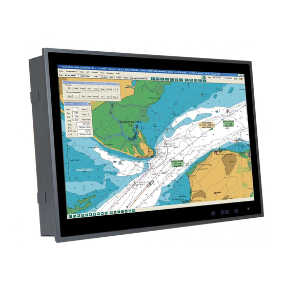
- Page 1 S19M/S24M Marine Monitor MODEL: S19M/S24M 19”/24” Marine Monitor with AC and DC Redundant Power, Projected Capacitive Touchscreen, IP 66 Compliant Front Panel and IP 22 Compliant Rear Cover User Manual User Manual Page i Rev. 1.00 – November 27, 2015...
- Page 2 S19M/S24M Marine Monitor Revision Date Version Changes November 27, 2015 1.00 Initial release Page ii...
- Page 3 S19M/S24M Marine Monitor Copyright COPYRIGHT NOTICE The information in this document is subject to change without prior notice in order to improve reliability, design and function and does not represent a commitment on the part of the manufacturer. In no event will the manufacturer be liable for direct, indirect, special, incidental, or consequential damages arising out of the use or inability to use the product or documentation, even if advised of the possibility of such damages.
- Page 4 S19M/S24M Marine Monitor Manual Conventions WARNING Warnings appear where overlooked details may cause damage to the equipment or result in personal injury. Warnings should be taken seriously. CAUTION Cautionary messages should be heeded to help reduce the chance of losing data or damaging the product.
-
Page 5: Table Of Contents
S19M/S24M Marine Monitor Table of Contents 1 INTRODUCTION......................1 1.1 O ........................2 VERVIEW 1.2 M ....................2 ODEL ARIATIONS 1.3 F ........................3 EATURES 1.4 F ......................3 RONT ANEL 1.4.1 Display Control Buttons..................4 1.5 B ......................4... - Page 6 S19M/S24M Marine Monitor 3.3.9 VGA Inputs ....................... 24 3.3.10 VGA Output....................24 3.4 T ............... 25 URNING FF THE ARINE ONITOR 4 ON-SCREEN DISPLAY (OSD) CONTROLS............26 4.1 OSD C ..................27 ONTROL UTTONS 4.2 OSD M ..............28 TRUCTURE AND PTIONS 5 IEI MONITOR REMOTE APPLICATION..............
- Page 7 Figure 1-1: S19M/S24M Marine Monitor..................2 Figure 1-2: Front Panel ........................3 Figure 1-3: Display Control Buttons .....................4 Figure 1-4: Bottom Panel .......................5 Figure 1-5: S19M Rear Panel ......................5 Figure 1-6: S24M Rear Panel ......................6 Figure 1-7: S19M Dimensions (mm)....................9 Figure 1-8: S24M Dimensions (mm)....................10 Figure 3-1: S19M Cutout Dimensions..................17...
- Page 8 S19M/S24M Marine Monitor List of Tables Table 1-1: Model Variations ......................2 Table 1-2: System Specifications....................8 Table 3-1: Panel Mounting Clamps .....................18 Table 3-2: Buzzer Terminal Block Pinouts.................20 Table 3-3: DVI Input Connector Pinouts..................21 Table 3-4: RJ-45 Connector Pinouts...................22 Table 3-5: RS-232 Connector Pinouts ..................22 Table 3-6: RS-422/485 Terminal Block Pinouts .................23...
-
Page 9: Introduction
S19M/S24M Marine Monitor Chapter Introduction Page 1... -
Page 10: Overview
22 compliant rear cover, is the latest member of IEI’s line of sophisticated LCD designs. With two VGA, two DVI and one BNC inputs, the S19M/S24M provides multiple ways to connect with computers. In addition, one VGA and one BNC outputs allow simultaneous display on other monitors. -
Page 11: Features
Isolated AC and DC inputs with redundant power protection 1.4 Front Panel The front side of the S19M/S24M (Figure 1-2) is a flat panel LCD screen surrounded by an aluminum frame. The bottom frame includes four OSD buttons and an ambient light sensor. -
Page 12: Display Control Buttons
Figure 1-3: Display Control Buttons 1.5 Bottom Panel The bottom panel of the S19M/S24M has the following I/O interfaces (Figure 1-4): 1 x 100 V ~ 240 V AC power input jack 1 x 18 V ~ 36 V DC power input terminal block... -
Page 13: Rear Panel
S19M/S24M Marine Monitor Figure 1-4: Bottom Panel 1.6 Rear Panel The rear panel provides access to retention screw holes that support VESA mounting. See Figure 1-5 and Figure 1-6. Figure 1-5: S19M Rear Panel Page 5... -
Page 14: System Specifications
S19M/S24M Marine Monitor Figure 1-6: S24M Rear Panel 1.7 System Specifications The technical specifications for the S19M/S24M are listed in Table 1-2. Specifications S19M S24M 19" 24” LCD Size PMVA AMVA Panel Type 1280 x 1024 (5:4) 1920 x 1080 (16:9) Max. - Page 15 S19M/S24M Marine Monitor Specifications S19M S24M 50,000 50,000 Backlight MTBF (HRs) EXC3188 (10-point) Touch Controller Projected capacitive type Touchscreen STDP8028 Scalar Chip DVI-D signal input: 2 x DVI (24-pin, female) VGA signal input: 2 x D-sub (15-pin, female) VGA signal output: 1 x D-sub (15-pin, female, clone of...
-
Page 16: Table 1-2: System Specifications
S19M/S24M Marine Monitor Specifications S19M S24M 5% ~ 95% RH Operating Humidity Fanless Thermal Design Aluminum front, sheet metal rear (Black C) Housing Cut-out Dimensions 442 mm x 373 mm 576 mm x 356 mm (L x W) 463 mm x 394 mm x 76 mm... -
Page 17: Dimensions
S19M/S24M Marine Monitor 1.8 Dimensions The 19M dimensions are shown below. Figure 1-7: S19M Dimensions (mm) Page 9... -
Page 18: Figure 1-8: S24M Dimensions (Mm)
S19M/S24M Marine Monitor The S24M dimensions are shown below. Figure 1-8: S24M Dimensions (mm) Page 10... -
Page 19: Unpacking
S19M/S24M Marine Monitor Chapter Unpacking Page 11... -
Page 20: Anti-Static Precautions
When the S19M/S24M is unpacked, please do the following: Follow the anti-static precautions outlined in Section 2.1. Make sure the packing box is facing upwards so the S19M/S24M does not fall out of the box. Make sure all the components shown in Section 2.3 are present. -
Page 21: Packing List
NOTE: If any of the components listed in the checklist below are missing, do not proceed with the installation. Contact the IEI reseller or vendor the S19M/S24M was purchased from or contact an IEI sales representative directly by sending an email to ales@ieiworld.com. -
Page 22: Optional Items
S19M/S24M Marine Monitor 2.4 Optional Items The following are optional components which may be separately purchased: Item and Part Number Image Panel mounting kit (P/N: PK-S19M-R10) (P/N: PK-S24M-R10) Desktop stand (P/N: STAND-A21-R10) Page 14... -
Page 23: Installation
S19M/S24M Marine Monitor Chapter Installation Page 15... -
Page 24: Installation Precautions
3.2 Mounting the Monitor WARNING: When mounting the S19M/S24M marine monitor onto a panel, it is better to have more than one person to help with the installation to make sure the S19M/S24M does not fall down and get damaged. -
Page 25: Panel Mounting
S19M/S24M Marine Monitor 3.2.1 Panel Mounting To mount the S19M/S24M marine monitor into a panel, please follow the steps below. Select the position on the panel to mount the S19M/S24M. Step 1: Cut out a section of the panel that corresponds to the rear panel dimensions of Step 2: the S19M/S24M. -
Page 26: Figure 3-3: S24M Panel Mounting Hole Covers
S19M/S24M Marine Monitor Remove the panel mounting hole covers from the rear panel. Each cover is Step 3: secured to the rear panel with a retention screw. Remove the retention screw to remove the cover. Figure 3-3: S24M Panel Mounting Hole Covers... -
Page 27: Stand Mounting
Figure 3-4: Tighten the Panel Mounting Clamp Screws 3.2.2 Stand Mounting To mount the S19M/S24M using the stand mounting kit, please follow the steps below. Locate the screw holes on the rear of the S19M/S24M (Figure 1-5 and Figure Step 1: 1-6). -
Page 28: I/O Interfaces
The S19M/S24M has the following I/O interfaces (Figure 3-5): Figure 3-5: I/O Interfaces 3.3.1 BNC Video Input and Output The S19M/S24M equips with one BNC video input and one BNC video output connectors. Refer to Figure 3-5 for the connector locations. 3.3.2 Buzzer The buzzer terminal block allows connection to a buzzer. -
Page 29: Dvi Inputs
Table 3-3: DVI Input Connector Pinouts 3.3.4 Power Inputs The S19M/S24M provides two types of power inputs: 18V ~ 36V DC power and 100V ~ 240V AC power. Refer to Figure 3-5 for the locations of the power input connectors. -
Page 30: For Remote Control
3.3V_NL Table 3-4: RJ-45 Connector Pinouts 3.3.6 RS-232 for Remote Control The S19M/S24M provides an RS-232 DB-9 connector for remote control. NOTE: The default baud rate for the RS-232 connector is 38,400 bps. To change the baud rate for the connector, the user has to modify the firmware of the AD board. -
Page 31: Rs-422/485 For Remote Control
S19M/S24M Marine Monitor 3.3.7 RS-422/485 for Remote Control The S19M/S24M provides an RS-422/485 terminal block for remote control. NOTE: The default baud rate for the RS-422/485 connector is 38,400 bps. To change the baud rate for the connector, the user has to modify the firmware of the AD board. -
Page 32: Vga Inputs
S19M/S24M Marine Monitor 3.3.9 VGA Inputs The S19M/S24M provides two VGA input connectors. Refer to Figure 3-5 for the connector locations. Description Description GREEN BLUE DDCDAT HSYNC VSYNC DDCCLK Table 3-7: VGA Output Connector Pinouts 3.3.10 VGA Output The S19M/S24M provides one VGA output connector. Refer to Figure 3-5 for the connector location. -
Page 33: Turning On/Off The Marine Monitor
Ensure the marine monitor is connected to a power source. Refer to Section Step 1: 3.3.4 for detailed information of the power input connectors on the S19M/S24M. Press the button located on the bottom right corner of the front panel to Step 2: turn on or off the monitor. -
Page 34: On-Screen Display (Osd) Controls
S19M/S24M Marine Monitor Chapter On-Screen Display (OSD) Controls Page 26... -
Page 35: Osd Control Buttons
S19M/S24M Marine Monitor 4.1 OSD Control Buttons The OSD control buttons are located on the bottom right corner of the front panel. Figure 4-1: OSD Button Locations The function of each button is described in the following table. Press this button to open the OSD window. -
Page 36: Osd Menu Structure And Options
S19M/S24M Marine Monitor 4.2 OSD Menu Structure and Options Figure 4-2: Main Menu Table 4-2 shows the OSD menu structure and options for the S19M/S24M marine monitor. Level 0 Level 1 Values/Options Backlight 0 to 100 Brightness 0 to 100... - Page 37 S19M/S24M Marine Monitor Level 0 Level 1 Values/Options Auto AR Off, On Aspect Ratio Full Screen, 1:1, Aspect Ratio PIP Mode Off, Small PIP, Side-by-Side PIP Size 1 to 7 Vertical Position 0 to 100 Display Settings Horizontal Position 0 to 100...
-
Page 38: Table 4-2: Osd Menu Structure And Options
S19M/S24M Marine Monitor Level 0 Level 1 Values/Options Film Mode Detection Video-3:2, Video-3:2-2:2, Off, Video-2:2 Film Mode & Film Display Mode Not available to be configured Scaling Vert. Dynamic Scaling Not available to be configured Horiz. Dynamic Scaling Not available to be configured... -
Page 39: Iei Monitor Remote Application
S19M/S24M Marine Monitor Chapter IEI Monitor Remote Application Page 31... -
Page 40: Overview
S19M/S24M Marine Monitor 5.1 Overview The IEI Monitor Remote Application allows remote control of the marine monitor via LAN, RS-232 or RS-422/485 connection to a computer. Refer to the following sections for detailed information. 5.2 Launching the IEI Monitor Remote Application Insert the driver CD into an optical disk drive connected to the system. -
Page 41: Figure 5-2: Iei Monitor Remote Ap - Rs-232
S19M/S24M Marine Monitor NOTE: The application will scan from COM1 to COM5 of the computer and will use the interface (RS-232 or RS-422/485) which is being detected first. If the user wants to use RS-232 interface, but the RS-422/485 connection is being detected first, please unplug the RS-422/485 cable from the computer. -
Page 42: Remote Control Via Rs-422/485
S19M/S24M Marine Monitor 5.4 Remote Control via RS-422/485 To remotely control the marine monitor via RS-422/485 connection, please follow the steps below. Ensure the marine monitor is connected to the computer via the RS-422/485 Step 1: interface. Refer to Figure 1-4 for the location of the RS-422/485 terminal block on the S19M/S24M. -
Page 43: Remote Control Via Lan
Ensure the marine monitor is connected to the network via the RJ-45 interface. Step 1: Refer to Figure 1-4 for the location of the RJ-45 connector on the S19M/S24M. NOTE: The marine monitor and the computer should be under the same domain. -
Page 44: Figure 5-4: Iei Monitor Remote Ap - Lan
S19M/S24M Marine Monitor Click the LAN tab. The ID and IP address of the connected marine monitors Step 2: should be displayed on the device list (Figure 5-4). If the device ID and IP address are not being displayed, click Scan Device to detect the connected marine monitor again. -
Page 45: A Regulatory Compliance
S19M/S24M Marine Monitor Appendix Regulatory Compliance Page 37... - Page 46 S19M/S24M Marine Monitor DECLARATION OF CONFORMITY This equipment is in conformity with the following EU directives: EMC Directive 2004/108/EC Low-Voltage Directive 2006/95/EC RoHS II Directive 2011/65/EU Ecodesign Directive 2009/125/EC If the user modifies and/or install other devices in the equipment, the CE conformity declaration may no longer apply.
- Page 47 S19M/S24M Marine Monitor Español [Spanish] IEI Integration Corp declara que el equipo cumple con los requisitos esenciales y cualesquiera otras disposiciones aplicables o exigibles de la Directiva 1999/5/CE. Ελληνική [Greek] IEI Integration Corp ΔΗΛΩΝΕΙ ΟΤΙ ΕΞΟΠΛΙΣΜΟΣ ΣΥΜΜΟΡΦΩΝΕΤΑΙ ΠΡΟΣ ΤΙΣ ΟΥΣΙΩΔΕΙΣ ΑΠΑΙΤΗΣΕΙΣ ΚΑΙ ΤΙΣ ΛΟΙΠΕΣ ΣΧΕΤΙΚΕΣ ΔΙΑΤΑΞΕΙΣ ΤΗΣ ΟΔΗΓΙΑΣ...
- Page 48 S19M/S24M Marine Monitor Româna [Romanian] IEI Integration Corp declară că acest echipament este in conformitate cu cerinţele esenţiale şi cu celelalte prevederi relevante ale Directivei 1999/5/CE. Slovensko [Slovenian] IEI Integration Corp izjavlja, da je ta opreme v skladu z bistvenimi zahtevami in ostalimi relevantnimi določili direktive 1999/5/ES.
- Page 49 S19M/S24M Marine Monitor FCC WARNING This equipment complies with Part 15 of the FCC Rules. Operation is subject to the following two conditions: This device may not cause harmful interference, and This device must accept any interference received, including interference that may cause undesired operation.
-
Page 50: B Safety Precautions
S19M/S24M Marine Monitor Appendix Safety Precautions Page 42... -
Page 51: Safety Precautions
Do not apply voltage levels that exceed the specified voltage range. Doing so may cause fire and/or an electrical shock. Electric shocks can occur if the S19M/S24M chassis is opened when the S19M/S24M is running. Do not drop or insert any objects into the ventilation openings of the S19M/S24M. -
Page 52: Anti-Static Precautions
Electrostatic discharge (ESD) can cause serious damage to electronic components, including the S19M/S24M. Dry climates are especially susceptible to ESD. It is therefore critical that whenever the S19M/S24M is opened and any of the electrical components are handled, the following anti-static precautions are strictly adhered to. -
Page 53: Product Disposal
Please follow the national guidelines for electrical and electronic product disposal. B.2 Maintenance and Cleaning Precautions When maintaining or cleaning the S19M/S24M, please follow the guidelines below. B.2.1 Maintenance and Cleaning Prior to cleaning any part or component of the S19M/S24M, please read the details below. Page 45... -
Page 54: Cleaning Tools
In such case, the product will be explicitly mentioned in the cleaning tips. Below is a list of items to use when cleaning the S19M/S24M. Cloth – Although paper towels or tissues can be used, a soft, clean piece of cloth is recommended when cleaning the S19M/S24M. -
Page 55: C Hazardous Materials Disclosure
S19M/S24M Marine Monitor Appendix Hazardous Materials Disclosure Page 47... -
Page 56: Hazardous Material Disclosure Table For Ipb Products Certified As Rohs Compliant Under 2002/95/Ec Without Mercury
S19M/S24M Marine Monitor C.1 Hazardous Material Disclosure Table for IPB Products Certified as RoHS Compliant Under 2002/95/EC Without Mercury The details provided in this appendix are to ensure that the product is compliant with the Peoples Republic of China (China) RoHS standards. The table below acknowledges the presences of small quantities of certain materials in the product, and is applicable to China RoHS only. - Page 57 S19M/S24M Marine Monitor Part Name Toxic or Hazardous Substances and Elements Lead Mercury Cadmium Hexavalent Polybrominated Polybrominated (Pb) (Hg) (Cd) Chromium Biphenyls Diphenyl Ethers (CR(VI)) (PBB) (PBDE) Housing Display Printed Circuit Board Metal Fasteners Cable Assembly Fan Assembly Power Supply...
- Page 58 S19M/S24M Marine Monitor 此附件旨在确保本产品符合中国 RoHS 标准。以下表格标示此产品中某有毒物质的含量符 合中国 RoHS 标准规定的限量要求。 本产品上会附有”环境友好使用期限”的标签,此期限是估算这些物质”不会有泄漏或突变”的 年限。本产品可能包含有较短的环境友好使用期限的可替换元件,像是电池或灯管,这些元 件将会单独标示出来。 部件名称 有毒有害物质或元素 铅 汞 镉 六价铬 多溴联苯 多溴二苯醚 (Pb) (Hg) (Cd) (CR(VI)) (PBB) (PBDE) 壳体 显示 印刷电路板 金属螺帽 电缆组装 风扇组装 电力供应组装 电池 O: 表示该有毒有害物质在该部件所有物质材料中的含量均在 SJ/T11363-2006 标准规定的限量要求以下。 X: 表示该有毒有害物质至少在该部件的某一均质材料中的含量超出 SJ/T11363-2006 标准规定的限量要求。...
Need help?
Do you have a question about the S19M and is the answer not in the manual?
Questions and answers