
Subscribe to Our Youtube Channel
Related Manuals for IEI Technology LCD-KIT-F Series


Summary of Contents for IEI Technology LCD-KIT-F Series
- Page 1 LCD-KIT-F MODEL: LCD-KIT-F S e rie s 12.1" ~ 19" Op e n Fra m e LCD Mo n ito r VGA, DVI-D, Ro HS Us e r Ma n u a l P a g e i Re v. 1.00 – 6 J u n e , 2016...
- Page 2 LCD-KIT-F Re vis io n Date Version Changes 6 June, 2016 1.00 Initial release P a g e ii...
- Page 3 LCD-KIT-F Co p yrig h t COP YRIGHT NOTICE The information in this document is subject to change without prior notice in order to improve reliability, design and function and does not represent a commitment on the part of the manufacturer. In no event will the manufacturer be liable for direct, indirect, special, incidental, or consequential damages arising out of the use or inability to use the product or documentation, even if advised of the possibility of such damages.
- Page 4 LCD-KIT-F Ma n u a l Co n ve n tio n s WARNING Warnings appear where overlooked details may cause damage to the equipment or result in personal injury. Warnings should be taken seriously. CAUTION Cautionary messages should be heeded to help reduce the chance of losing data or damaging the product.
-
Page 5: Table Of Contents
LCD-KIT-F Ta b le o f Co n te n ts 1 INTRODUCTION ......................1 1.1 LCD-KIT-F S LCD M ............2 ERIES ONITOR VERVIEW 1.2 F ........................2 EATURES 1.3 M ..................... 3 ODEL ARIATIONS 1.4 A ......................4 PPLICATIONS 1.5 E .................... - Page 6 LCD-KIT-F 3.1.4 LCD-KIT-F19A LCD Specifications ..............19 3.2 P ..................... 20 OWER DAPTERS 3.3 9~36V DC M ....................20 ODULE 4 AD BOARD ........................21 4.1 AD B ....................22 OARD VERVIEW 4.2 AV-60381 AD B ....................22 OARD 4.2.1 AV-60381 Peripheral Interface Connectors ............. 22 4.2.2 Backlight Inverter Connector (INVERTER1) ..........
- Page 7 LCD-KIT-F 5.4.6 USB for Touch Panel Connector ..............36 5.5 M LCD-KIT-F S LCD M ..........36 OUNTING THE ERIES ONITOR 5.5.1 Panel Mounting ....................36 6 ON-SCREEN-DISPLAY (OSD) CONTROLS ............. 41 6.1 OSD K ......................42 EYPAD 6.2 OSD M ....................
- Page 8 LCD-KIT-F C.4 S ..................72 OFTWARE LLUSTRATION C.4.1 Manage Page ....................75 C.4.2 EDID Page ...................... 76 C.4.3 Image Page ...................... 77 C.4.4 Display Page (for analog signal) ..............78 C.4.5 Color Page ...................... 79 C.4.6 PIP Page......................80 C.4.7 System Page ..................... 81 C.4.8 About Page ......................
- Page 9 LCD-KIT-F Lis t o f Fig u re s Figure 1 1: LCD-KIT-F Series ......................2 Figure 1-2: Typical LCD-KIT-F Front View ................... 4 Figure 1-3: Typical LCD-KIT-F Rear View ..................5 Figure 1-4: Typical LCD-KIT Connectors ..................6 Figure 2-1: Rear Panel ........................9 Figure 2-2: LCD-KIT-F-12A Physical Dimensions (millimeters) ..........11...
- Page 10 LCD-KIT-F Figure 6-7: OSD Settings Menu ....................49 Figure 7-1: Setup Icon ........................52 Figure 7-2: Welcome Screen .......................53 Figure 7-3: License Agreement ....................53 Figure 7-4: Initiate Install ......................54 Figure 7-5: Installation Starts ......................54 Figure 7-6: Finish Installation ......................55 Figure 7-7: PenMount Monitor Icon ....................56 Figure 7-8: PenMount Monitor Popup Menu ................56 Figure 7-9: Configuration Screen ....................56 Figure 7-10: Calibration Initiation Screen ..................57...
- Page 11 LCD-KIT-F Lis t o f Ta b le s Table 1-1: LCD-KIT-F Series Model Variations ................3 Table 2-1: General Physical Dimensions ...................10 Table 2-2: Mounting Holes ......................15 Table 3-1: LCD-KIT-F12A LCD Specifications ................17 Table 3-2: LCD-KIT-F15A LCD Specifications ................18 Table 3-3: LCD-KIT-F17A LCD Specifications ................19...
-
Page 12: Introduction
LCD-KIT-F Ch a p te r In tro d u c tio n P a g e 1... -
Page 13: Lcd-Kit-F Series Lcd Monitor Overview
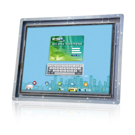
1.1 LCD-KIT-F S e rie s LCD Mo n ito r Ove rvie w Figure 1 1: LCD-KIT-F Series The LCD-KIT-F series LCD monitor is the latest member of IEI’s line of sophisticated LCD designs, and it has been improved to be RoHS compliant. It is designed to fit industrial automation, or any other applications that require minimum installation space and flexible configuration. -
Page 14: Model Variations
LCD-KIT-F 1.3 Mo d e l Va ria tio n s The LCD-KIT-F series offer the following model variations. Model Number Description LCD-KIT-F12A-R10 12.1" 600 cd/m² XGA open frame monitor, VGA and DVI-D input, R10 LCD-KIT-F15A-R10 15" 450 cd/m² XGA open frame monitor, VGA and DVI-D input, R10 LCD-KIT-F17A-R10 17"... -
Page 15: Applications
The following sections describe the physical layout of the LCD-KIT-F series LCD monitors. 1.5.1 Fro n t Vie w The front of the LCD-KIT-F series LCD monitor is a flat panel TFT LCD screen attached to a metal chassis. F igure 1-2 shows a typical LCD-KIT-F front view. -
Page 16: Connectors
LCD-KIT-F Auto Left Right Menu The OSD panel also has one power LED. F igure 1-3 shows a typical LCD-KIT-F rear panel. 3 6 3 H Figure 1-3: Typical LCD-KIT-F Rear View 1.5.3 Co n n e c to rs Each LCD-KIT series LCD monitor has a number of interface connectors on the I/O panel of the chassis (when viewing the rear panel). -
Page 17: Series Specifications
LCD-KIT-F Figure 1-4: Typical LCD-KIT Connectors 1.6 S e rie s Sp e c ific a tio n s The table below shows the LCD-KIT-F Series specifications. Model LCD-KIT-F12A LCD-KIT-F15A LCD-KIT-F17A LCD-KIT-F19A LCD Size 12.1" 15” 17” 19" Resolution 1024 x 768... -
Page 18: Certifications
SPCC Mounting Panel Mount, Rear Mount, VESA 100 1.7 Ce rtific a tio n s All LCD-KIT-F series LCD monitor models comply with the following international standards: RoHS For a more detailed description of these standards, please refer to Appendix D. -
Page 19: Mechanical Overview
LCD-KIT-F Ch a p te r Me c h a n ic a l Ove rvie w P a g e 8... -
Page 20: Introduction
2.2 Re a r P a n e l The following models of the LCD-KIT-F series LCD monitor have an OSD control panel located vertically along the left side of the rear panel: ... -
Page 21: Available Connectors
LCD monitor. 2.4.1 Ge n e ra l P h ys ic a l Dim e n s io n s General physical dimensions for the LCD-KIT-F series LCD monitors are shown in T able 3 7 2 H 2-1. -
Page 22: Lcd-Kit-F-12A Physical Dimensions
LCD-KIT-F 2.4.2 LCD-KIT-F-12A P h ys ic a l Dim e n s io n s The physical dimensions of the LCD-KIT-F-12A are shown in F igure 2-5. 3 7 5 H Figure 2-2: LCD-KIT-F-12A Physical Dimensions (millimeters) P a g e 11... -
Page 23: Lcd-Kit-F-15A Physical Dimensions
LCD-KIT-F 2.4.3 LCD-KIT-F-15A P h ys ic a l Dim e n s io n s The physical dimensions of the LCD-KIT-F-15A are shown in F igure 2-3. 3 7 5 H Figure 2-3: LCD-KIT-F-15A Physical Dimensions (millimeters) P a g e 12... -
Page 24: Lcd-Kit-F-17A Physical Dimensions
LCD-KIT-F 2.4.4 LCD-KIT-F-17A P h ys ic a l Dim e n s io n s The physical dimensions of the LCD-KIT-F-17A are shown in F igure 2-4. 3 7 5 H Figure 2-4: LCD-KIT-F-17A Physical Dimensions (millimeters) P a g e 13... -
Page 25: Lcd-Kit-F-19A Physical Dimensions
LCD-KIT-F 2.4.5 LCD-KIT-F-19A P h ys ic a l Dim e n s io n s The physical dimensions of the LCD-KIT-F-19A are shown in F igure 2-5. 3 7 5 H Figure 2-5: LCD-KIT-F-19A Physical Dimensions (millimeters) P a g e 14... -
Page 26: Mounting Holes
LCD-KIT-F 2.5 Mo u n tin g Ho le s Each LCD-KIT-F series LCD monitor has mounting holes located on the rear panel. T able 3 8 0 H 2-2 details the number of mounting holes for each model of the LCD-KIT series LCD monitor. -
Page 27: Lcd Specifications
LCD-KIT-F Ch a p te r LCD S p e c ific a tio n s P a g e 16... -
Page 28: Lcd Specifications
LCD-KIT-F 3.1 LCD Sp e c ific a tio ns Detailed specifications for the LCD screens are listed in the following sections. 3.1.1 LCD-KIT-F12A LCD S p e c ific a tio n s The table below lists the LCD-KIT-F12A LCD specifications. Ite m s LCD-KIT-F12A S ize... -
Page 29: Lcd-Kit-F17A Lcd Specifications
LCD-KIT-F Ba c klig h t Brig h tn e s s (c d /m 2) 1024 x 768 Re s o lu tio n S c re e n S c a le 70000H Life Tim e 800:1 Co n tra s t Ra tio 160/150 Vie w An g le (H/V) 1ch LVDS... -
Page 30: Lcd-Kit-F19A Lcd Specifications
LCD-KIT-F 2ch LVDS In te rfa c e -30°C ~70°C Op e ra tin g Te m p e ra tu re 337.920 x 270.336 Ac tive Are a (m m ) 0.264 P ixe l P itc h (m m ) Normal White Dis p la y Mo d e 16.7M... -
Page 31: Power Adapters
LCD-KIT-F 3.2 P owe r Ad a p te rs T able 3-6 lists the power adapter specifications. 3 8 2 H Model FSP036-RBBN2 Input Voltage Range 90-264VAC Input Frequency 47-63Hz Output Voltage 12 V Output Voltage Output Watts Efficiency Operating Temperature 0°C~40°C Storage Temperature... -
Page 32: Ad Board
LCD-KIT-F Ch a p te r AD Bo a rd P a g e 21... -
Page 33: Ad Board Overview
LCD-KIT-F 4.1 AD Bo a rd Ove rvie w The LCD-KIT-F series LCD monitor AD board provides a wide variety of control interfaces. The following sections describe each AD board in detail. 4.2 AV-60381 AD Bo a rd The connector locations of the AV-60381 are shown in Figure 4-1. The Pin 1 locations of the on-board connectors are also indicated in the diagrams below. -
Page 34: Backlight Inverter Connector (Inverter1)
LCD-KIT-F COM debug port connector 2-pin wafer, p=2.00 mm LVDS connector 30-pin crimp, p=1.25 mm LVDS1 OSD keypad connector 12-pin wafer, p=1.00 mm KEYPAD1 Power input connector 3-pin wafer, p=3.96 mm PWR2 Power input connector (+12 V) 2-pin wafer, p=2.00 mm CN15 Power output connector 2-pin wafer, p=2.00 mm... -
Page 35: Lvds Connector (Lvds1)
LCD-KIT-F Table 4-2: Backlight Inverter Connector (INVERTER1) Pinouts 4.2.3 LVDS Co n n e c to r (LVDS 1) PIN NO. DESCRIPTION PIN NO. DESCRIPTION A0P_C A0M_C A1P_C A1M_C A2P_C A2M_C CLK1P_C CLK1M_C A3P_C A3M_C A4P_C A4M_C A5P_C A5M_C A6P_C A6M_C CLK2P_C CLK2M_C... -
Page 36: Power Input Connector (Pwr2)
LCD-KIT-F 4.2.5 P owe r In p u t Co n n e c to r (P WR2) PIN NO. DESCRIPTION +9 V ~ +36 V to external power module +12 V input Table 4-5: Power Input Connector (PWR2) Pinouts 4.2.6 RS -232 Co n n e c to r for To u c h s c re e n (RS 232_1) PIN NO. -
Page 37: Vga Connector (Vga2)
LCD-KIT-F PIN NO. DESCRIPTION PIN NO. DESCRIPTION Table 4-8: Touchscreen Connector (J1) Pinouts 4.2.9 VGA Co n n e c to r (VGA2) PIN NO. DESCRIPTION PIN NO. DESCRIPTION SMCLK GREEN SMDATA BLUE H-SYNC V-SYNC Table 4-9: VGA Connector (VGA2) Pinouts 4.2.10 Ba c klig h t Vo lta g e S e le c t J u m p e r (J P 5) DESCRIPTION Short 1-2... -
Page 38: Power Input Setting Jumper (Jp4)
LCD-KIT-F 4.2.12 P owe r In p u t S e ttin g J u m p e r (J P 4) DESCRIPTION Short 1-3, 2-4 +12 V from power jack (PRW1) Input with external connector Short 3-5, 4-6 (external power module is needed) Table 4-12: Power Input Setting Jumper (JP4) Pinouts 4.2.13 To u c h s c re e n Typ e S e le c t J u m pe r (J P 1) DESCRIPTION... -
Page 39: Installation
LCD-KIT-F Ch a p te r In s ta lla tio n P a g e 28... -
Page 40: Installation Precautions
LCD-KIT-F 5.1 In s ta lla tio n P re c a u tio n s When installing the LCD-KIT-F series LCD monitor, please follow the precautions listed below: Read the user manual: The user manual provides a complete description of the LCD-KIT-F series LCD monitor, installation instructions and configuration options. -
Page 41: Unpacking
5.2 Un pa c kin g 5.2.1 P a c ka g in g When shipped, the LCD-KIT-F series LCD monitor is wrapped in a plastic bag. Two polystyrene ends are placed on either side of the monitor. The monitor is then placed into a first (internal) cardboard box. -
Page 42: Packing List
LCD-KIT-F 5.2.3 P a c kin g Lis t All the monitors in the LCD-KIT-F series are shipped with the following components: Qu a n tity Ite m Im a g e S ta n d a rd LCD-KIT series LCD monitor... -
Page 43: Pre - Installation Preparation
5.3 P re -in s ta lla tio n P re pa ra tio n 5.3.1 To o ls Before installing the LCD-KIT-F series LCD monitor, make sure the following tools are on hand: Philips (crosshead) screwdriver: All the retention screws on the system are Philips screws. -
Page 44: Vga Connector
LCD-KIT-F 12V DC 9~36V Te rm in a l LCD-KIT DVI-D US B RS -232 J a c k Blo c k LCD-KIT-F19A/TW-R10 Optional LCD-KIT-F12A/PC-R10 Optional LCD-KIT-F15A/PC-R10 Optional LCD-KIT-F17A/PC-R10 Optional LCD-KIT-F19A/PC-R10 Optional Table 5-1: Rear Panel Connectors 5.4.1 VGA Co n n e c to r Use the rear panel standard 15-pin female VGA connector to connect the LCD monitor to the system graphics interface. -
Page 45: Power Connector
LCD-KIT-F TMDS Data2+ PVDD1 TMDS Data0- DDC Clock [SCL] TMDS Data0+ DDC Data [SDA] Analog vertical sync TMDS Data1- TMDS Data1+ TMDS Clock + TMDS Clock - Table 5-3: DVI-D Connector Pinouts Figure 5-2: DVI-D Connector 5.4.3 12V P owe r Co n n e c to r Use the rear panel +12V DC jack to connect the monitor to a power source. -
Page 46: Rs-232 For Touch Panel Connector
LCD-KIT-F Figure 5-4: 3-pin Terminal Block 5.4.5 RS -232 fo r To uc h P a n e l Co n n e c to r Use the rear panel standard RS-232 DB-9 female touch panel connector to connect the monitor to the system graphics interface. -
Page 47: Usb For Touch Panel Connector
5.5.1 P a n e l Mo u n tin g Each model of the LCD-KIT-F series LCD monitor has a series of mounting slots located on the top, side and bottom panels for mounting the monitor to a panel. -
Page 48: Figure 5-7: Mounting Clamps Holder
LCD-KIT-F Figure 5-7: Mounting Clamps Holder Figure 5-8: Mounting Clamps To mount the LCD-KIT-F series LCD monitor into a panel, please follow the steps below. Select the position on the panel to mount the monitor. S te p 1: Cut out a section of the panel that corresponds to the rear panel dimensions of S te p 2: the monitor. -
Page 49: Figure 5-9: Secure The Mounting Clamps Holders
LCD-KIT-F Figure 5-9: Secure the Mounting Clamps Holders Slide the monitor through the hole until the aluminum frame is flush against the S te p 4: panel. S te p 5: Insert the panel mounting clamps into the pre-formed holes of the clamp holders. -
Page 50: Figure 5-11: Mounting Clamps Holder Dimensions
LCD-KIT-F Figure 5-11: Mounting Clamps Holder Dimensions Figure 5-12: Ultra Set Plate Dimensions Figure 5-13: Bolt Dimensions P a g e 39... -
Page 51: Figure 5-14: Steering Button Dimensions
LCD-KIT-F Figure 5-14: Steering Button Dimensions P a g e 40... -
Page 52: On-Screen-Display (Osd) Controls
LCD-KIT-F Ch a p te r On -S c re e n -Dis p la y (OS D) Co n tro ls P a g e 41... -
Page 53: Osd Keypad
LCD-KIT-F 6.1 OS D Ke ypa d There are several on-screen-display (OSD) control buttons of the OSD keypad on the monitor rear panel. Figure 6-1 shows the 5-key membrane OSD keypad of the LCD monitors. Figure 6-1: OSD Keypad The function of each button is described in the following table. LCD ON/OFF Press this button to turn on or turn off the LCD screen. -
Page 54: Osd Menu Structure
LCD-KIT-F 6.2 OS D Me n u Stru c tu re T able 6-2 shows the OSD menu structure for all models of the DM-F series LCD monitor. 5 7 2 H Level 0 Level 1 Level 2 Value Image Brightness 0 to 100 Contrast... -
Page 55: Using The Osd
LCD-KIT-F 6.3 Us in g th e OS D OSD menu options are described below. 6.3.1 Im a g e Me n u Image menu features are shown in Figure 6-2. Figure 6-2: Image Menu The brightness option adjusts the brightness of screen. This function Brightness adjusts the offset value of ADC. -
Page 56: Color Setting
LCD-KIT-F 6.3.1.1 Co lo r S e ttin g Color settings are shown in Figure 6-3. Figure 6-3: Color Settings auto Automatically adjusts the color settings. This item allows adjustment of the following items. Color temp 5000k – NTSC standard Kelvin ... -
Page 57: Display Menu
LCD-KIT-F 6.3.2 Dis p la y Me n u Display menu features are shown in Figure 6-4. Figure 6-4: Display Menu Auto Adjust Automatically adjusts the LCD screen position. Phase Adjusts the input signal (analog only) Clock Adjusts the dot clock position Display Position Adjusts the horizontal and vertical position of the display screen Display Mode This item allows adjustment of the Gamma. -
Page 58: System Menu
LCD-KIT-F 6.3.3 S ys te m Me n u System menu features are shown in Figure 6-5. Figure 6-5: System Menu Input Allows selection of input device to use. (Figure 6-6) OSD Settings Provides options for OSD configuration. (Figure 6-7) Provides information on the LCD monitor, such as firmware version, Information release date and input resolution. -
Page 59: Input
LCD-KIT-F 6.3.3.1 In p u t Input options are shown in Figure 6-6. Figure 6-6: Input Options Input options are described below. Display Port This item sets the input device to display port. This item sets the input device to VGA. HDMI This item sets the input device to HDMI. -
Page 60: Osd Settings
LCD-KIT-F 6.3.3.2 OS D S e ttin g s The OSD settings are shown in Figure 6-7. Figure 6-7: OSD Settings Menu OSD settings are described below. Determines how many seconds the OSD screen stays on screen Timer before it disappears when OSD is left unattended. Adjusts the OSD rotation angle on the screen. -
Page 61: Software Driver
LCD-KIT-F Ch a p te r S o ftwa re Drive r P a g e 50... -
Page 62: Introduction
LCD-KIT-F 7.1 In tro d u c tio n The touch panel controller enables analog resistive touch panels for four-wire, five-wire & eight-wire models. The controller directly communicates with the PC system through the touch panel communications interface. The controller design is superior in sensitivity, accuracy, and friendly operation. -
Page 63: Touch Panel Driver Installation
LCD-KIT-F USB Interface: If the touch screen interface connection is a USB connection, connect the USB connector on the single board computer to the external USB port connector of the LCD-KIT-F monitor. 7.3 To u c h P a n e l Drive r In s ta lla tio n WARNING: Before the touch screen driver is installed, make sure the system is connected to the monitor with a USB cable or an RS-232 null cable. -
Page 64: Figure 7-2: Welcome Screen
LCD-KIT-F Double click the setup icon in Figure 7-1. S te p 10: The Welcome screen in Figure 7-2 appears. S te p 11: Figure 7-2: Welcome Screen Click Next to continue. S te p 12: The license agreement in Figure 7-3 appears. Accept the terms of the S te p 13: agreement by clicking I Agree. -
Page 65: Figure 7-4: Initiate Install
LCD-KIT-F The installation destination screen appears. See Figure 7-4. Click Install. S te p 14: Figure 7-4: Initiate Install The installation of the program begins. See Figure 7-5. S te p 15: Figure 7-5: Installation Starts When the installation is complete, the complete screen appears. See Figure 7-6. S te p 16: To complete the installation process click Finish. -
Page 66: Change The Touch Screen Interface
LCD-KIT-F Figure 7-6: Finish Installation 7.4 Ch a n g e th e To u c h S c re e n In te rfa c e If the touch screen interface must be changed from an RS-232 interface to a USB interface or, from a USB interface to an RS-232 interface, the following steps must be followed. -
Page 67: Figure 7-7: Penmount Monitor Icon
LCD-KIT-F S te p 3: Locate the PenMount Monitor icon in the bottom left corner of the screen. Figure 7-7: PenMount Monitor Icon S te p 4: Click the icon. A pop up menu appears. See Figure 7-8. Figure 7-8: PenMount Monitor Popup Menu Click Control Panel in the pop up menu shown in Figure 7-8. -
Page 68: Figure 7-10: Calibration Initiation Screen
LCD-KIT-F Double click the PenMount 6000 icon as shown in Figure 7-9. S te p 7: The calibration initiation screen in Figure 7-10 appears. S te p 8: Select the Standard Calibration button as shown in Figure 7-10. S te p 9: Figure 7-10: Calibration Initiation Screen S te p 10: The calibration screen in is shown. -
Page 69: A Regulatory Compliance
LCD-KIT-F Ap p e n d ix 3 9 6 H Re g u la to ry Co m p lia n c e P a g e 58... - Page 70 LCD-KIT-F DECLARATION OF CONFORMITY This equipment is in conformity with the following EU directives: EMC Directive (2004/108/EC, 2014/30/EU) Low-Voltage Directive (2006/95/EC, 2014/35/EU) RoHS II Directive (2011/65/EU, 2015/863/EU) Ecodesign Directive 2009/125/EC If the user modifies and/or install other devices in the equipment, the CE conformity declaration may no longer apply.
- Page 71 LCD-KIT-F Eesti [Estonian] IEI Integration Corp deklareerib seadme seadme vastavust direktiivi 2014/53/EÜ põhinõuetele ja nimetatud direktiivist tulenevatele teistele asjakohastele sätetele. Español [Spanish] IEI Integration Corp declara que el equipo cumple con los requisitos esenciales y cualesquiera otras disposiciones aplicables o exigibles de la Directiva 2014/53/EU.
- Page 72 LCD-KIT-F Magyar [Hungarian] IEI Integration Corp nyilatkozom, hogy a berendezés megfelel a vonatkozó alapvetõ követelményeknek és az 2014/53/EU irányelv egyéb elõírásainak. Polski [Polish] IEI Integration Corp oświadcza, że wyrobu jest zgodny z zasadniczymi wymogami oraz pozostałymi stosownymi postanowieniami Dyrektywy 2014/53/EU. Português [Portuguese] IEI Integration Corp declara que este equipamento está...
-
Page 73: B Safety Precautions
LCD-KIT-F Ap p e n d ix S a fe ty P re c a u tio n s P a g e 62... -
Page 74: Safety Precautions
LCD-KIT-F WARNING: The precautions outlined in this chapter should be strictly followed. Failure to follow these precautions may result in permanent damage to the LCD-KIT-F. B.1 S a fe ty P re c a u tio n s Please follow the safety precautions outlined in the sections that follow: B.1.1 Ge n e ra l S a fe ty P re c a u tio n s Please ensure the following safety precautions are adhered to at all times. -
Page 75: Anti-Static Precautions
LCD-KIT-F If considerable amounts of dust, water, or fluids enter the device, turn off the power supply immediately, unplug the power cord, and contact the LCD-KIT-F vendor. DO NOT: Drop the device against a hard surface. Strike or exert excessive force onto the LCD panel. Touch any of the LCD panels with a sharp object In a site where the ambient temperature exceeds the rated temperature B.1.2 An ti-s ta tic P re c a u tio n s... -
Page 76: Product Disposal
LCD-KIT-F B.1.3 P ro d u c t Dis p o s a l CAUTION: Risk of explosion if battery is replaced by an incorrect type. Only certified engineers should replace the on-board battery. Dispose of used batteries according to instructions and local regulations. -
Page 77: Maintenance And Cleaning Precautions
LCD-KIT-F B.2 Ma in te n a n c e a n d Cle a n in g P re c a u tio n s When maintaining or cleaning the LCD-KIT-F, please follow the guidelines below. WARNING: For safety reasons, turn-off the power and unplug the panel PC before cleaning. - Page 78 LCD-KIT-F can be used to clean the device. Using solvents–The use of solvents is not recommended when cleaning the device as they may damage the plastic parts. Vacuum cleaner–Using a vacuum specifically designed for computers is one of the best methods of cleaning the device. Dust and dirt can restrict the airflow in the device and cause its circuitry to corrode.
-
Page 79: C Smartosd
LCD-KIT-F Ap p e n d ix s m a rtOS D P a g e 68... -
Page 80: Iei Smart Osd Quick Installation Guide
LCD-KIT-F C.1 IEI s m a rtOS D Qu ic k In s ta lla tio n Gu id e IEI smartOSD is a proprietary On-Screen-Display (OSD) software solution from IEI that enables easy, remote monitor setting adjustments in a Windows environment. IEI smartOSD delivers excellent performance and provides more flexibility than the typical OSD hardware solutions when adjusting a monitor. - Page 81 LCD-KIT-F Figure C-1: smartOSD Welcome Screen S te p 4: Click Next to continue. The Folder Select screen in F igure C-2 appears. S te p 5: 5 9 2 H Figure C-2: smartOSD Folder Select Screen Select the installation folder in F igure C-2 shown above.
- Page 82 LCD-KIT-F Figure C-3: smartOSD Confirm Installation S te p 9: Confirm the installation by clicking Next in the screen above. S te p 10: The program starts to install and the progress bar shown in F Igure C-4 appears. 5 9 5 H Figure C-4: smartOSD Installation Progress S te p 11: When the installation is complete the “Complete Installation”...
-
Page 83: Software Illustration
LCD-KIT-F Figure C-5: smartOSD Installation Complete S te p 12: Click Close in the screen above. S te p 13: After quick setup is complete, the IEI smartOSD wizard logo appears on the desktop as shown in the screen below. S te p 14: To access the smartOSD, click the smartOSD wizard logo.S te p 0:... - Page 84 LCD-KIT-F NOTE: To update the display setting status immediately, push the refresh button on every page To turn the system on, press ALT + P. Ite m Ele m e n ts Management Save/Load File Power Management EDID EDID contains basic information about the monitor and its capabilities.
-
Page 85: Table C-1: Smartosd Menu Structure
LCD-KIT-F Auto Brightness (disabled in the DM-F Series) Main Source Input (YPbPr, S-Video and CVBS disabled) Volume (disabled in the DM-F Series) Factory Presets/OSD Lock/OSD Unlock Mute (disabled in the DM-F Series) Table C-1: SmartOSD Menu Structure P a g e 74... -
Page 86: Manage Page
LCD-KIT-F C.4.1 Ma n a g e P a g e Figure C-6: Manage Page P a g e 75... -
Page 87: Edid Page
LCD-KIT-F C.4.2 EDID P a g e Figure C-7: EDID Page P a g e 76... -
Page 88: Image Page
LCD-KIT-F C.4.3 Im a g e P a g e Figure C-8: Image Page P a g e 77... -
Page 89: Display Page (For Analog Signal)
LCD-KIT-F C.4.4 Dis p la y P a g e (fo r a n a lo g s ig n a l) Figure C-9: Display Page P a g e 78... -
Page 90: Color Page
LCD-KIT-F C.4.5 Co lo r P a g e Figure C-10: Color Page P a g e 79... -
Page 91: Pip Page
LCD-KIT-F C.4.6 P IP P a ge NOTE: The functions in the PIP page are only available in the MLCD-KIT Series and AFOLUX Series monitors. Figure C-11: PIP Page P a g e 80... -
Page 92: System Page
LCD-KIT-F C.4.7 S ys te m P a g e Figure C-12: System Page NOTE: Some of the functions in the System Page are only available to some of the IEI LCD series as following: Auto Brightness: SRM, MLCD-KIT and AFOLUX series only ... -
Page 93: About Page
LCD-KIT-F C.4.8 Ab o u t P a g e Figure C-13: About Page P a g e 82... -
Page 94: Smart Osd Faq
LCD-KIT-F C.5 s m a rtOS D FAQ For troubleshooting, please see the steps below: C.5.1 Win d ows 2000 In s ta lla tio n Fa ilu re Installation fails under Windows 2000 and shows the following image: Figure C-14: DLL Missing Solution: Download and install service pack Windows Installer 3.1 C.5.2 Vis ta In s ta lla tio n Fa ilu re Installation fail under Vista while showing following image:... -
Page 95: Model Failure
LCD-KIT-F Solution: Install SmartOSD.exe as the administrator authority Figure C-16: Install as Administrator C.5.3 Mo d e l Fa ilu re The Model Fail error message shown below appears. Figure C-17: Firmware Incompatibility Solution: SmartOSD only supports firmware version 2.0 and following versions. P a g e 84... -
Page 96: Ddc Port Failure
LCD-KIT-F C.5.4 DDC P o rt Fa ilu re The DDC port fail error message shown below appears. Figure C-18: DDC Port Failure Solutions: Check VGA or HDMI cable Check an IEI monitor is being used Make sure the version is version 2.3 for the AFOLUX/MDM series and version 1.5 for the DM/ISDM/TDM/SRM/LCD-KIT series that have the SmartOSD functions ... -
Page 97: D Hazardous Materials Disclosure
LCD-KIT-F Ap p e n d ix Ha za rd o u s Ma te ria ls Dis c lo s u re P a g e 86... - Page 98 LCD-KIT-F The details provided in this appendix are to ensure that the product is compliant with the Peoples Republic of China (China) RoHS standards. The table below acknowledges the presences of small quantities of certain materials in the product, and is applicable to China RoHS only.
- Page 99 LCD-KIT-F 此附件旨在确保本产品符合中国 RoHS 标准。以下表格标示此产品中某有毒物质的含量符 合中国 RoHS 标准规定的限量要求。 本产品上会附有”环境友好使用期限”的标签,此期限是估算这些物质”不会有泄漏或突变”的 年限。本产品可能包含有较短的环境友好使用期限的可替换元件,像是电池或灯管,这些元 件将会单独标示出来。 部件名称 有毒有害物质或元素 铅 汞 镉 六价铬 多溴联苯 多溴二苯 醚 (P b ) (Hg ) (Cd ) (CR(VI)) (P BB) (P BDE) 壳体 显示 印刷电路板 金属螺帽 电缆组装 风扇组装 电力供应组装 电池 O: 表示该有毒有害物质在该部件所有物质材料中的含量均在 SJ/T 11363-2006 (现由 GB/T 26572-2011 取代) 标准规定的限量要求以下。...
Need help?
Do you have a question about the LCD-KIT-F Series and is the answer not in the manual?
Questions and answers