Sign In
Upload
Manuals
Brands
IEI Technology Manuals
Monitor
SRM-KIT Series
IEI Technology SRM-KIT Series Manuals
Manuals and User Guides for IEI Technology SRM-KIT Series. We have
1
IEI Technology SRM-KIT Series manual available for free PDF download: User Manual
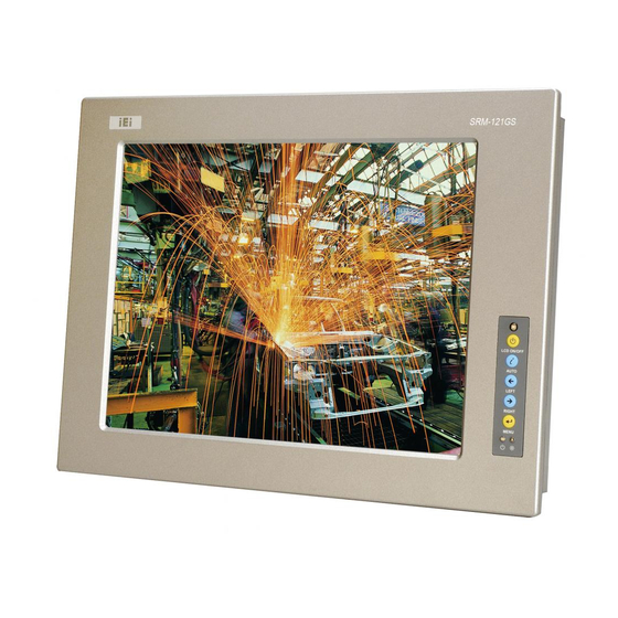
IEI Technology SRM-KIT Series User Manual (77 pages)
High Brightness Industrial Monitor, RoHS Compliance Auto-Dimming, OSD COntrol, VGA, DVI-D, 12V Input
Brand:
IEI Technology
| Category:
Monitor
| Size: 3 MB
Table of Contents
Packing List
4
Table of Contents
9
1 Introduction
15
Srm-Kit Series Lcd Monitor Overview
16
Standard Features
16
SRM-KIT Series Industrial Monitor Applications
16
Model Variations
17
External Overview
17
Figure 1-1: Front View
17
Front View
17
Figure 1-3: SRM-KIT Series Connectors
19
Figure 1-4: AV-5300 AD Board
20
Table 1-1: SRM-KIT Series Specifications
21
Figure 1-5: SRM-KIT121G Physical Dimensions (Millimeters)
22
Physical Dimensions
22
SRM-KIT121G Physical Dimensions
22
Figure 1-6: SRM-KIT150G Physical Dimensions (Millimeters)
23
SRM-KIT150G Physical Dimensions
23
Figure 1-7: Sizes of Mounting Holes
24
Figure 1-8: Monitor Arm or Stand Mounting
24
Mounting Options
24
Series Specifications
20
Certification
21
Figure 1-2: Rear View
18
Rear View
18
Ad Board
19
Connectors
19
2 Lcd Specifications
25
Lcd Specifications
26
LCD Overview
26
SRM-KIT121G LCD Specifications
26
SRM-KIT150G LCD Specifications
27
Table 2-1: SRM-KIT121G LCD Specifications
27
Table 2-2: SRM-KIT150G LCD Specifications
28
Power Adapters
29
Table 2-3: Power Adapter Specifications
29
3 Ad Board
31
Av-5300 Ad Board Overview
32
Figure 3-1: AV-5300 AD Board Overview
32
Figure 3-2: Connector and Jumper Locations
34
AV-5300 Peripheral Interface Connectors
35
AV-5300 Rear Panel Connectors
35
AV-5300 AD Board Connectors
33
AV-5300 AD Board Layout
34
Table 3-2: AV-5300 Rear Panel Connectors
35
Table 3-1: AV-5300 Peripheral Interface Connectors
35
Figure 3-3: Auto-Dimming Connector Location
37
Table 3-4: Auto-Dimming Connector Pinouts
37
Table 3-5: Debug Port Connector Pinouts
37
External OSD and LED Indication Connector
38
Table 3-6: External OSD and LED Indication Connector Pinouts
38
Backlight Inverter Connector
39
Table 3-3: AV-5300 On-Board Jumpers
36
Debug Port Connector
37
Av-5300 Internal Peripheral Connectors
36
Auto-Dimming Connector
36
AV-5300 On-Board Jumpers
36
Figure 3-4: Debug Port Connector Location
38
Figure 3-5: External OSD and LED Indication Connector Location
39
Table 3-7: Backlight Inverter Connector Pinouts
39
Figure 3-7: LVDS Output Connector Location
41
Power Output Connector
41
Table 3-8: LVDS Output Connector Pinouts
41
Figure 3-8: Power Output Connector Locations
42
Power Input Connector
42
Table 3-10: Power Output Connector Pinouts (CN13)
42
Table 3-9: Power Output Connector Pinouts (CN12)
42
Figure 3-9: Power Input Connector Locations
43
Table 3-11: Power Input Connector Pinouts (CN24)
43
Table 3-12: Power Input Connector Pinouts (CN25)
43
VGA Connector
43
Figure 3-10: VGA Connector Location
44
Table 3-13: VGA Connector Pinouts
44
AV-5300 On-Board Jumpers
45
Figure 3-11: Jumpers
45
Figure 3-12: Jumper Locations
45
LCD Panel Power Input Jumper
46
LCD Panel Voltage Select Jumper
46
Table 3-14: LCD Panel Power Input Jumper Settings
46
Table 3-15: LCD Panel Voltage Select Jumper Settings
46
AV-5300 External (Rear Panel) Connectors
47
DC 12V Connector
47
Table 3-16: DC 12V Connector Pinouts
47
DVI-D Connector
48
VGA Connector
48
Figure 3-6: Backlight Inverter Connector Location
40
LVDS Output Connector
40
Figure 3-13: AV-5300 External (Rear Panel) Connectors
47
Table 3-17: VGA Connector Pinouts
48
Figure 3-14: VGA Connector Pinout Locations
48
Table 3-18: DVI-D Connector Pinouts
49
Figure 3-15: DVI-D Connector Pinout Locations
49
4 Installation
51
Installation Precautions
52
Unpacking
53
Packaging
53
Unpacking Procedure
53
Packing List
54
Pre-Installation Preparation
54
Tools
54
Voltage Select Jumper Settings
55
Connectors
55
DVI-D Connector
56
Table 4-2: VGA Connector Pinouts
56
Figure 4-1: VGA Connector Pinout Locations
56
VGA Connector
56
Figure 4-3: 12V Power Connector
57
Figure 4-2: DVI-D Connector Pinout Locations
57
Power Connector
57
Table 4-3: DVI-D Connector Pinouts
57
Table 4-1: External Peripheral Interface Connectors
56
Mounting the Srm-Kit Series Lcd Monitor
58
5 On-Screen-Display (Osd) Controls
59
Figure 5-1: OSD Control Buttons for All Models
60
User Mode Osd Structure
60
OSD Buttons
60
OSD Menu Structure
61
Table 5-1: OSD Menus
62
Figure 5-3: Color Options
64
Figure 5-4: Image Settings Menu
65
Figure 5-5: OSD Configurations Menu
66
OSD Configurations
66
Auto-Dimming Configurations
67
Figure 5-6: Signal Menu
67
Signal
67
Default Settings
68
Image Settings
65
Using the Osd
62
Main Display Features
62
Figure 5-2: Main Display Features
63
Color
64
Light
68
Table 5-3: Auto-Dimming Default Settings
68
Table 5-2: LUX Measurement of Everyday Light Source
68
Figure 5-7: SRM-KIT121G Default Linearity of the LCD Backlight and Ambient Light
69
Figure 5-8: Auto-Dimming Configurations Menu
69
Changing the Default Settings
70
OSD Control
69
Figure 5-9: Decreasing LUX Max. Value
71
Figure 5-10: Light Max, Light Min and LUX Min in Default Value
72
Acertification
73
Rohs Compliant
74
A.1 Roh Compliant
74
Bindex
75
Advertisement
Advertisement
Related Products
IEI Technology SRM-150
IEI Technology SRM-150A
IEI Technology S19M
IEI Technology S24M
IEI Technology SEG-M
IEI Technology SPCIE-C2260-i2
IEI Technology SAILORPC-12A
IEI Technology S19A-QM87i-i
IEI Technology SPCIE-C2160
IEI Technology SPCIE-3600AM2
IEI Technology Categories
Motherboard
Touch Panel
Computer Hardware
Single board computers
Desktop
More IEI Technology Manuals
Login
Sign In
OR
Sign in with Facebook
Sign in with Google
Upload manual
Upload from disk
Upload from URL