Table of Contents

Related Manuals for IEI Technology DM-150GS/R-R30


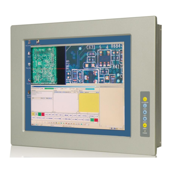
Summary of Contents for IEI Technology DM-150GS/R-R30
- Page 1 DM S e rie s Mo n ito r DM Series Industrial Monitor IEI Te c h n o lo g y Co rp . MODEL: DM S e rie s 15”~19” LCD Mo n ito r VGA/DVI-D, IP 65 P ro te c tio n , Ro HS Us e r Ma n u a l P a g e I Re v.
- Page 2 DM S e rie s Mo n ito r Re vis io n Date Version Changes 7 June, 2013 3.00 Initial Release P a g e II...
- Page 3 DM S e rie s Mo n ito r Co p yrig h t COP YRIGHT NOTICE The information in this document is subject to change without prior notice in order to improve reliability, design and function and does not represent a commitment on the part of the manufacturer.
-
Page 4: Table Of Contents
DM S e rie s Mo n ito r Ta b le o f Co n te n ts 1 INTRODUCTION ......................1 1.1 O ........................2 VERVIEW 1.2 F ........................2 EATURES 1.3 M ....................3 ODEL ARIATIONS 1.4 A ...................... - Page 5 DM S e rie s Mo n ito r 3.1 LCD S ....................20 PECIFICATIONS 3.1.1 LCD Overview ....................20 3.1.2 DM-150 LCD Specifications ................20 3.1.3 DM-170 LCD Specifications ................21 3.1.4 DM-190 LCD Specifications ................21 4 AD BOARD ........................23 4.1 AD B .....................
- Page 6 DM S e rie s Mo n ito r 5.5.4 Monitor Stand Installation ................45 5.5.5 Monitor Arm Installation ................. 47 6 ON-SCREEN-DISPLAY (OSD) CONTROLS ............48 6.1 U OSD S ................. 49 TRUCTURE 6.1.1 OSD Buttons ..................... 49 6.1.2 OSD Menu Structure ..................50 6.2 U OSD .......................
- Page 7 DM S e rie s Mo n ito r OSD I ....................71 SMART NSTALL C.4 S ..................75 OFTWARE LLUSTRATION C.4.1 Manage Page ....................77 C.4.2 EDID Page ...................... 78 C.4.3 Image Page ...................... 79 C.4.4 Display Page (for analog signal) ..............80 C.4.5 Color Page ......................
- Page 8 DM S e rie s Mo n ito r Lis t o f Fig u re s Figure 1-1: DM Series ........................2 Figure 1-2: Typical Monitor Front View ..................5 Figure 1-3: Bottom Panel View ...................... 5 Figure 1-4: AV-6600 AD Board ...................... 6 Figure 2-1: Front Panel Variant 1 ....................11 Figure 2-2: Front Panel Variant 2 ....................12 Figure 2-3: DM-150 Physical Dimensions (millimeters) ............14...
- Page 9 DM S e rie s Mo n ito r Figure 5-21: VESA Mounting Holes ....................46 Figure 5-22: Monitor Stand Mounting ..................46 Figure 5-23: Monitor Arm Mounting ....................47 Figure 6-1: OSD Control Buttons ....................49 Figure 6-2: Main Display Features ....................51 Figure 6-3: Color Options ......................52 Figure 6-4: OSD Configurations Menu ..................53 Figure 7-1: Setup Icon ........................56 Figure 7-2: Welcome Screen .......................57...
- Page 10 DM S e rie s Mo n ito r Lis t o f Ta b le s Table 1-1: DM Series Model Variations ..................3 Table 1-2: DM Series Specifications ..................... 8 Table 2-1: Front Panel Variants ....................10 Table 2-2: General Physical Dimensions ...................13 Table 2-3: DM-150 Mounting Kits ....................17 Table 2-4: DM-170 Mounting Kits ....................18 Table 2-5: DM-190 Mounting Kits ....................18...
-
Page 11: Introduction
DM S e rie s Mo n ito r Ch a p te r In tro d u c tio n P a g e 1... -
Page 12: Overview
DM S e rie s Mo n ito r 1.1 Ove rvie w Figure 1-1: DM Series The DM series LCD monitor is the latest member of IEI’s line of sophisticated LCD designs, and it has been improved to be RoHS compliant. It is designed to fit industrial automation, or any other applications that require minimum installation space and flexible configuration. -
Page 13: Model Variations
17” LCD screen DM-190: 19” LCD screen The DM series LCD monitor base models have a variety of variants. The model variations are listed in Table 1-1. 9~36V Power Model Number Input DM-150GS/R-R30 15” DM-150GMS/R-R30 DM-170GS/R-R30 17” DM-170GMS/R-R30 DM-190GS/R-R30 19” DM-190GMS/R-R30 Table 1-1: DM Series Model Variations 1.4 Ap p lic a tio n s... -
Page 14: External Overview
DM S e rie s Mo n ito r Plant environment monitoring Factory automation HMI terminal Shop-floor/MES control Self-service Kiosk Full-service receptionist kiosk Hospital self-registrating terminal Interactive photo kiosk Video rental kiosk Self-service POS terminal 1.5 Exte rn a l Ove rview The DM series LCD monitors are durable devices that can be used in harsh industrial environments. -
Page 15: Bottom Panel View
DM S e rie s Mo n ito r Figure 1-2: Typical Monitor Front View 1.5.2 Bo tto m P a n e l View Figure 1-3 shows the bottom panel of the DM series LCD monitor. All connectors are fully described in Section 5.4. -
Page 16: Ad Board
DM S e rie s Mo n ito r 1.5.3 AD Bo a rd The DM series LCD monitor AD board provides a wide variety of control interfaces, receiving and managing signals from a CPU card through cabling. Figure 1-4 shows the AV-6600 AD board as a sample of a typical AD board for the DM series LCD monitor. -
Page 17: Series Specifications
DM S e rie s Mo n ito r 1.6 S e rie s Sp e c ific a tio n s Table 1-2 shows the DM Series specifications. Model DM-150GS DM-150GMS DM-170GS DM-170GMS DM-190GS DM-190GMS LCD Size 15” 15” 17”... -
Page 18: Certifications
DM S e rie s Mo n ito r Model DM-150GS DM-150GMS DM-170GS DM-170GMS DM-190GS DM-190GMS Power Adapter Internal Internal Internal Internal Internal Internal Certificates Prescan Prescan Prescan Prescan Prescan Prescan EMC Class A EMC Class A EMC Class A EMC Class A EMC Class A EMC Class A... -
Page 19: Mechanical Overview
DM S e rie s Mo n ito r Ch a p te r Me c h a n ic a l Ove rvie w P a g e 9... -
Page 20: Introduction
DM S e rie s Mo n ito r 2.1 In tro d u c tio n This chapter describes the general mechanical overview of the DM series monitors including front and bottom panel variations, available interfaces and overall dimensions. 2.2 Fro n t P a n e l The front panel of the DM series LCD monitor is comprised of a LCD in an aluminum frame with an OSD control panel. -
Page 21: Front Panel Variant 2
DM S e rie s Mo n ito r Figure 2-1: Front Panel Variant 1 2.2.3 Fro n t P a n e l Va ria n t 2 The following model of the DM series LCD monitor has an OSD control panel located horizontally along the bottom of the aluminum frame: ... -
Page 22: Bottom Panel
DM S e rie s Mo n ito r Figure 2-2: Front Panel Variant 2 2.2.4 Bo tto m P a n e l All peripheral device connectors are located on the bottom panel of the DM series LCD monitor. The following sections describe the bottom panel variants and their associated connectors. -
Page 23: Physical Dimensions
DM S e rie s Mo n ito r 2.3 P h ys ic a l Dim e n s io n s The following sections describe the physical dimensions for each model of the DM series LCD monitor. 2.3.1 Ge n e ra l P h ys ic a l Dim e n s io n s General physical dimensions for the DM series LCD monitors are shown in Table 2-2. -
Page 24: Dm-150 Physical Dimensions
DM S e rie s Mo n ito r 2.3.2 DM-150 P h ys ic a l Dim e n s io n s The physical dimensions of the DM-150 are shown in Figure 2-3. Figure 2-3: DM-150 Physical Dimensions (millimeters) P a g e 14... -
Page 25: Dm-170 Physical Dimensions
DM S e rie s Mo n ito r 2.3.3 DM-170 P h ys ic a l Dim e n s io n s The physical dimensions of the DM-170 are shown in Figure 2-4. Figure 2-4: DM-170 Physical Dimensions (millimeters) P a g e 15... -
Page 26: Dm-190 Physical Dimensions
DM S e rie s Mo n ito r 2.3.4 DM-190 P h ys ic a l Dim e n s io n s The physical dimensions of the DM-190 are shown in Figure 2-5. Figure 2-5: DM-190 Physical Dimensions (millimeters) P a g e 16... -
Page 27: Optional Mounting Kits
DM S e rie s Mo n ito r 2.3.5 Op tio n a l Mo u n tin g Kits The following sections describe the various optional mounting kits available for each model of the DM series LCD monitor. Refer to Section 5.5 for detailed instructions on the different mounting methods for the monitors. -
Page 28: Dm-190 Mounting Kits
DM S e rie s Mo n ito r LCD Monitor Stand STAND-100-RS Table 2-4: DM-170 Mounting Kits 2.3.8 DM-190 Mo u n tin g Kits Table 2-5 lists the mounting kits available for the DM-190 monitor. Model DM-190 Panel Mounting Kit PK-190M Rack Mounting Kit RK-190MS-R10... -
Page 29: Lcd Specifications
DM S e rie s Mo n ito r Ch a p te r LCD S p e c ific a tio n s P a g e 19... -
Page 30: Lcd Specifications
DM S e rie s Mo n ito r 3.1 LCD Sp e c ific a tio ns 3.1.1 LCD Ove rvie w The DM series LCD monitors use the following LCD panels. DM-150: AUO G150XG01 V3 DM-170: AUO G170EG01 V1 ... -
Page 31: Dm-170 Lcd Specifications
DM S e rie s Mo n ito r 3.1.3 DM-170 LCD Sp e c ific a tio n s Table 3-2 lists the DM-170 LCD specifications. Ite m s DM-170 Size 17” Brand Model G170EG01 V1 Backlight Brightness (cd/m2) Resolution 1280 x 1024 Screen Scale... -
Page 32: Table 3-3: Dm-190 Lcd Specifications
DM S e rie s Mo n ito r Brightness (cd/m2) Resolution 1280 x 1024 Screen Scale Life Time 50000H Contrast Ratio 1000:1 View Angle (H/V) 170/160 Interface 2ch LVDS Operating Temperature 0~50°C Active Area (mm) 376.32 x 301.06 Pixel Pitch (mm) 0.294 Display Mode Normal White... -
Page 33: Ad Board
DM S e rie s Mo n ito r Ch a p te r AD Bo a rd P a g e 23... -
Page 34: Ad Board Overview
DM S e rie s Mo n ito r 4.1 AD Bo a rd Ove rvie w The DM series LCD monitor AD board provides a wide variety of control interfaces, receiving and managing interface signals from a CPU card through cabling. The following sections describe each AD board in detail. -
Page 35: Av-6600 Rear Panel Connectors
DM S e rie s Mo n ito r Co n n e c to r Typ e La b e l Audio input connector 4-pin wafer connector CN11 Audio speaker output connector 4-pin wafer connector CN12 Auto-dimming connector 6-pin wafer connector Debug connector 4-pin wafer connector External OSD and LED indication connector... -
Page 36: Installation
DM S e rie s Mo n ito r Ch a p te r In s ta lla tio n P a g e 26... -
Page 37: Installation Precautions
DM S e rie s Mo n ito r 5.1 In s ta lla tio n P re c a u tio n s When installing the DM series LCD monitor, please follow the precautions listed below: Read the user manual: The user manual provides a complete description of the DM series LCD monitor, installation instructions and configuration options. -
Page 38: Unpacking
DM S e rie s Mo n ito r 5.2 Un pa c kin g 5.2.1 P a c ka g in g When shipped, the DM series LCD monitor is wrapped in a plastic bag. Two polystyrene ends are placed on either side of the monitor. The monitor is then placed into a first (internal) cardboard box. -
Page 39: Packing List
DM S e rie s Mo n ito r 5.2.3 P a c kin g Lis t All the monitors in the DM series are shipped with the following components: 1 x DM-150/170/190 series LCD monitor. 1 x AC power cable ... -
Page 40: Voltage Select Jumper Settings
DM S e rie s Mo n ito r 5.3.2 Vo lta g e S e le c t J u m pe r S e ttin g s If the monitor comes with both 12V and 9~36V DC power connectors, the voltage select jumper on the integrated AD board must be configured for the DC connector that is used to power the monitor. -
Page 41: Connectors
DM S e rie s Mo n ito r 5.4 Co n n e c to rs Table 5-1 lists the rear panel connectors for the DM series LCD monitors. Connectors DM-150 DM-170 DM-190 DVI-D P o we r (12V J a c k) RS -232 fo r To u c h P a n e l US B fo r To u c h P a n e l P o we r (9~36V Te rm in a l Blo c k) -
Page 42: Vga Connector
DM S e rie s Mo n ito r Figure 5-1 shows all the possible rear panel connectors for the DM series LCD monitor. Refer to Table 5-1 for a list of the monitors and their corresponding connectors. The following sections fully describe the rear panel connectors for the DM series LCD monitor. 5.4.2 VGA Co n n e c to r Use the rear panel standard 15-pin female VGA connector to connect the monitor to the system graphics interface. -
Page 43: Power Connector
DM S e rie s Mo n ito r Analog vertical sync Hot Plug Detect TMDS Clock - Table 5-3: DVI-D Connector Pinouts Figure 5-3: DVI-D Connector 5.4.4 12V P owe r Co n n e c to r Use the rear panel +12V DC jack to connect the monitor to a power source. Figure 5-4: 12V Power Connector 5.4.5 RS -232 fo r To uc h P a n e l Co n n e c to r Use the rear panel standard RS-232 DB-9 female touch panel connector to connect the... -
Page 44: Usb For Touch Panel Connector
DM S e rie s Mo n ito r Figure 5-5: RS-232 Touch Panel Connector 5.4.6 US B fo r To u c h P a ne l Co n n e c to r Use the rear panel standard USB touch panel connector to connect the monitor to the system graphics interface. -
Page 45: Mounting The Monitor
DM S e rie s Mo n ito r Figure 5-7: Terminal Block 5.5 Mo u n tin g th e Mo n ito r The DM series LCD monitor can be mounted in a panel, cabinet, rack or wall. The monitor can also be mounted on a monitor arm or stand. -
Page 46: Figure 5-8: Dm-150 Panel Opening (Unit: Mm)
DM S e rie s Mo n ito r To mount the DM series LCD monitor into a panel, please follow the steps below. Select the position on the panel to mount the monitor. S te p 1: Cut out a section of the panel that corresponds to the rear panel dimensions of S te p 2: the monitor. -
Page 47: Figure 5-10: Dm-190 Panel Opening (Unit: Mm)
DM S e rie s Mo n ito r Figure 5-10: DM-190 Panel Opening (Unit: mm) S te p 3: Slide the monitor through the hole until the metal frame is flush against the panel (Figure 5-11). Figure 5-11: Insert the Monitor P a g e 37... -
Page 48: Cabinet And Rack Installation
DM S e rie s Mo n ito r S te p 4: Insert the panel mounting clamps into the pre-formed holes along the edges of the monitor, behind the metal frame. Refer to the mounting kit packing list for the required number of mounting clamps. -
Page 49: Standard Cabinet And Rack Installation
DM S e rie s Mo n ito r 5.5.2.1 Sta n d a rd Ca b in e t a nd Ra c k Ins ta lla tio n The standard cabinet/rack mounting procedure applies to the following DM series LCD monitors: ... -
Page 50: Figure 5-13: Secure The Cabinet/Rack Bracket
DM S e rie s Mo n ito r Figure 5-13: Secure the Cabinet/Rack Bracket S te p 5: Slide the monitor with the attached cabinet/rack bracket into a rack or cabinet (Figure 5-14). Figure 5-14: Install into a Cabinet/Rack P a g e 40... -
Page 51: Dm-190 Cabinet And Rack Installation
DM S e rie s Mo n ito r S te p 6: Once the monitor with the attached cabinet/rack has been properly inserted into the rack or cabinet, secure the front of the rack/cabinet bracket to the front of the rack or cabinet (Figure 5-14). -
Page 52: Figure 5-16: Rack Mounting Bracket Installation (Dm-190)
DM S e rie s Mo n ito r Figure 5-16: Rack Mounting Bracket Installation (DM-190) S te p 3: Carefully insert the slotted holes of the brackets on the monitor through the bolts on the rack and gently pull the monitor downwards until the bolts rests securely in the slotted holes. -
Page 53: Wall Mounting
DM S e rie s Mo n ito r 5.5.3 Wa ll Mo u n tin g CAUTION: Due to safety concerns, it is highly recommended to use the VESA mounting kits provided by IEI for wall, stand and arm mounting. If the VESA mounting kit is purchased separately, please make sure the mounting kit is UL-listed. -
Page 54: Figure 5-19: Monitor Support Screws
DM S e rie s Mo n ito r S te p 6: Insert the four monitor mounting screws (M4 screws) provided in the wall mounting kit into the four screw holes on the real panel of the monitor and tighten until the screw shank is secured against the rear panel (Figure 5-19). -
Page 55: Monitor Stand Installation
DM S e rie s Mo n ito r NOTE: In the diagram below the bracket is already installed on the wall. Figure 5-20: Wall Mounting the Monitor 5.5.4 Mo n ito r Sta n d In s ta lla tio n The DM series LCD monitor has Video Electronics Standards Association (VESA) standard mounting holes tapped into the rear panel. -
Page 56: Figure 5-21: Vesa Mounting Holes
DM S e rie s Mo n ito r Figure 5-21: VESA Mounting Holes The monitor stand mounting plate has a matching VESA hole pattern. To mount the DM series LCD monitor onto a stand, please follow the steps below. S te p 1: Line up the threaded holes on the monitor rear panel with the screw holes on the monitor stand mounting plate. -
Page 57: Monitor Arm Installation
DM S e rie s Mo n ito r 5.5.5 Mo n ito r Arm In s ta lla tio n The DM series LCD monitor has Video Electronics Standards Association (VESA) standard mounting holes tapped into the rear panel. The standard holes are M4 set at 100m x 100mm apart (Figure 5-21). -
Page 58: On-Screen-Display (Osd) Controls
DM S e rie s Mo n ito r Ch a p te r On -S c re e n -Dis p la y (OS D) Co n tro ls P a g e 48... -
Page 59: User Mode Osd Structure
DM S e rie s Mo n ito r 6.1 Us e r Mo d e OS D Stru c tu re 6.1.1 OS D Bu tto n s There are several on-screen-display (OSD) control buttons oriented either vertically along the right hand side or horizontally along the bottom of the monitor front panel. -
Page 60: Osd Menu Structure
DM S e rie s Mo n ito r 6.1.2 OS D Me n u Stru c tu re Table 6-1 shows the OSD menu structure for all models of the SRM series LCD monitor. Level 0 Level 1 Value Main Display Features Menu Brightness 0 to 100... -
Page 61: Using The Osd
DM S e rie s Mo n ito r 6.2 Us in g th e OS D OSD menu options are described below. 6.2.1 Ma in Dis p la y Fe a tu re s Main display features are shown in Figure 6-2. Figure 6-2: Main Display Features The brightness option adjusts the brightness of screen. -
Page 62: Color
DM S e rie s Mo n ito r 6.2.2 Co lo r Color options are shown in Figure 6-3. Figure 6-3: Color Options The Color menu fine-tunes the palette of color hues for the LCD. 6500k NTSC standard Kelvin 7500k NTSC standard Kelvin 9300k... -
Page 63: Osd Configurations
DM S e rie s Mo n ito r 6.2.3 OS D Co n fig u ra tio n s The OSD configurations are shown in Figure 6-4. Figure 6-4: OSD Configurations Menu OSD Configurations are described below. Determines how many seconds the OSD screen stays on screen OSD Time Out before it disappears when OSD is left unattended. -
Page 64: Software Drivers
DM S e rie s Mo n ito r Ch a p te r S o ftwa re Drive rs P a g e 54... -
Page 65: Introduction
DM S e rie s Mo n ito r 7.1 In tro d u c tio n The touch panel controller enables analog resistive touch panels for four-wire, five-wire & eight-wire models. The controller directly communicates with the PC system through the touch panel communications interface. -
Page 66: Touch Panel Driver Installation
DM S e rie s Mo n ito r USB Interface: If the touch screen interface connection is a USB connection, connect the USB connector on the single board computer to the external USB port connector of the DM Series monitor. 7.3 To u c h P a n e l Drive r In s ta lla tio n WARNING: Before the touch screen driver is installed, make sure the system is... -
Page 67: Figure 7-2: Welcome Screen
DM S e rie s Mo n ito r Double click the setup icon in Figure 7-1. S te p 4: The Welcome screen in Figure 7-2 appears. S te p 5: Figure 7-2: Welcome Screen Click Next to continue. S te p 6: The license agreement in Figure 7-3 appears. -
Page 68: Figure 7-4: Initiate Install
DM S e rie s Mo n ito r The installation destination screen appears. See Figure 7-4. Click Install. S te p 8: Figure 7-4: Initiate Install The installation of the program begins. See Figure 7-5. S te p 9: Figure 7-5: Installation Starts When the installation is complete, the complete screen appears. -
Page 69: Change The Touch Screen Interface
DM S e rie s Mo n ito r Figure 7-6: Finish Installation 7.4 Ch a n g e th e To u c h S c re e n In te rfa c e If the touch screen interface must be changed from an RS-232 interface to a USB interface or, from a USB interface to an RS-232 interface, the following steps must be followed. -
Page 70: Figure 7-7: Penmount Monitor Icon
DM S e rie s Mo n ito r S te p 3: Locate the PenMount Monitor icon in the bottom left corner of the screen. Figure 7-7: PenMount Monitor Icon S te p 4: Click the icon. A pop up menu appears. See Figure 7-8. Figure 7-8: PenMount Monitor Popup Menu Click Control Panel in the pop up menu shown in Figure 7-8. -
Page 71: Figure 7-10: Calibration Initiation Screen
DM S e rie s Mo n ito r Double click the PenMount 6000 icon as shown in Figure 7-9. S te p 7: The calibration initiation screen in Figure 7-10 appears. S te p 8: Select the Standard Calibration button as shown in Figure 7-10. S te p 9: Figure 7-10: Calibration Initiation Screen S te p 10:... -
Page 72: Gasket Replacement
DM S e rie s Mo n ito r Ch a p te r Ga s ke t Re p la c e m e n t P a g e 62... -
Page 73: Gasket Replacement
DM S e rie s Mo n ito r 8.1 Ga s ke t Re pla c e m e n t A gasket used for a long time may gradually lose its ability to protect the monitor from fluids and vapors; scratches or dirt may also accumulate. It is recommended that the gasket be replaced yearly. -
Page 74: A Safety Precautions
DM S e rie s Mo n ito r Ap p e n d ix S a fe ty P re c a u tio n s P a g e 64... -
Page 75: Safety Precautions
DM S e rie s Mo n ito r WARNING: The precautions outlined in this chapter should be strictly followed. Failure to follow these precautions may result in permanent damage to the DM Series. A.1 S a fe ty P re c a u tio n s Please follow the safety precautions outlined in the sections that follow: A.1.1 Ge n e ra l S a fe ty P re c a u tio n s Please ensure the following safety precautions are adhered to at all times. -
Page 76: Anti-Static Precautions
DM S e rie s Mo n ito r A.1.2 An ti-s ta tic P re c a u tio n s WARNING: Failure to take ESD precautions during the installation of the DM Series may result in permanent damage to the DM Series and severe injury to the user. -
Page 77: Cleaning Tools
DM S e rie s Mo n ito r The interior of the DM Series does not require cleaning. Keep fluids away from the DM Series interior. Be cautious of all small removable components when vacuuming the DM Series. -
Page 78: B Certifications
DM S e rie s Mo n ito r Ap p e n d ix Ce rtific a tio n s P a g e 68... -
Page 79: R Ohs Compliant
DM S e rie s Mo n ito r B.1 Ro HS Co m p lia n t All models in the DM LCD monitor series comply with the Restriction of Hazardous Materials (RoHS) Directive. This means that all components used to build the industrial workstations and the workstation itself are RoHS compliant. -
Page 80: C Smartosd
DM S e rie s Mo n ito r Ap p e n d ix s m a rtOS D P a g e 70... -
Page 81: Iei Smart Osd Quick Installation Guide
DM S e rie s Mo n ito r C.1 IEI s m a rtOS D Qu ic k In s ta lla tio n Gu id e IEI smartOSD is a proprietary On-Screen-Display (OSD) software solution from IEI that enables easy, remote monitor setting adjustments in a Windows environment. -
Page 82: Figure 8-2: Smartosd Installer
DM S e rie s Mo n ito r Figure 8-2: smartOSD Installer Click “Smart OSD” in Figure 8-2. S te p 2: The welcome screen shown in Figure 8-3 appears. S te p 3: Figure 8-3: smartOSD Welcome Screen Click Next to continue. -
Page 83: Figure 8-4: Smartosd Folder Select Screen
DM S e rie s Mo n ito r Figure 8-4: smartOSD Folder Select Screen S te p 6: Select the installation folder in Figure 8-4 shown above. Click Next to continue. S te p 7: The screen in Figure 8-5 appears. S te p 8: Figure 8-5: smartOSD Confirm Installation Confirm the installation by clicking Next in the screen above. -
Page 84: Figure 8-6: Smartosd Installation Progress
DM S e rie s Mo n ito r Figure 8-6: smartOSD Installation Progress S te p 11: When the installation is complete the “Complete Installation” screen in Figure 8-7 appears. Figure 8-7: smartOSD Installation Complete Click Close in the screen above. S te p 12: After quick setup is complete, the IEI smartOSD wizard logo appears on the S te p 13:... -
Page 85: Software Illustration
DM S e rie s Mo n ito r C.4 S o ftwa re Illu s tra tio n The table below shows the smartOSD menu structure for all IEI LCD monitors. NOTE: To update the display setting status immediately, push the refresh button on every page To turn the system on, press ALT + P. -
Page 86: Table C-1: Smartosd Menu Structure
DM S e rie s Mo n ito r Auto Adjust Display Phase Clock Color Auto Color User Red Gain User Green Gain User Blue Gain Color Temperature (5000k and 4200k disabled in the DM Series) Gamma PIP (disabled in the DM Series) PIP Source Input (disabled in the DM Series) PIP Size (disabled in the DM Series) Monitor Power Control... -
Page 87: Manage Page
DM S e rie s Mo n ito r C.4.1 Ma n a g e P a g e Figure 8-8: Manage Page P a g e 77... -
Page 88: Edid Page
DM S e rie s Mo n ito r C.4.2 EDID P a g e P a g e 78... -
Page 89: Image Page
DM S e rie s Mo n ito r C.4.3 Im a g e P a g e P a g e 79... -
Page 90: Display Page (For Analog Signal)
DM S e rie s Mo n ito r C.4.4 Dis p la y P a g e (fo r a n a lo g s ig n a l) P a g e 80... -
Page 91: Color Page
DM S e rie s Mo n ito r C.4.5 Co lo r P a g e P a g e 81... -
Page 92: Pip Page
DM S e rie s Mo n ito r C.4.6 P IP P a ge NOTE: The functions in the PIP page are only available in the MDM Series and AFOLUX Series monitors. P a g e 82... -
Page 93: System Page
DM S e rie s Mo n ito r C.4.7 S ys te m P a g e NOTE: Some of the functions in the System Page are only available to some of the IEI LCD series as following: Auto Brightness: SRM, MDM and AFOLUX series only ... -
Page 94: About Page
DM S e rie s Mo n ito r C.4.8 Ab o u t P a g e P a g e 84... -
Page 95: Smart Osd Faq
DM S e rie s Mo n ito r C.5 s m a rtOS D FAQ For troubleshooting, please see the steps below: C.5.1 Win d ows 2000 In s ta lla tio n Fa ilu re Installation fails under Windows 2000 and shows the following image: Figure C-9: DLL Missing Solution: Download and install service pack Windows Installer 3.1 C.5.2 Vis ta In s ta lla tio n Fa ilu re... -
Page 96: Model Failure
DM S e rie s Mo n ito r Solution: Install SmartOSD.exe as the administrator authority Figure C-11: Install as Administrator C.5.3 Mo d e l Fa ilu re The Model Fail error message shown below appears. Figure C-12: Firmware Incompatibility Solution: SmartOSD only supports firmware version 2.0 and following versions. -
Page 97: Dcc Port Failure
DM S e rie s Mo n ito r C.5.4 DDC P o rt Fa ilu re The DDC port fail error message shown below appears. Figure C-13: DCC Port Failure Solutions: Check VGA or DVI cable Check an IEI monitor is being used ...