Table of Contents
Advertisement
Quick Links
Advertisement
Table of Contents

Subscribe to Our Youtube Channel
Related Manuals for IEI Technology iSignager-LCD-S Series


Summary of Contents for IEI Technology iSignager-LCD-S Series
-
Page 1: User Manual
500A/510H iSignager-LCD-S Series User Manuall IEI Technology Corp. MODEL: iSignager-LCD-S Series 15"/17"/19" iSignager LCD with Audio Input/Output, Video Input, LAN, USB 2.0, IP 64 Compliant Front Panel Optional Wireless LAN Module User Manual (Hardware) Page i Rev. 1.01 – 23 June, 2009... - Page 2 Series Digital Signage Display Revision Date Version Changes 23 June, 2009 1.01 Added iSignager-LCD-W19S series information 15 September, 2008 1.00 Initial Release Page ii...
- Page 3 ISignager-LCD-S Series Digital Signage Display Copyright COPYRIGHT NOTICE The information in this document is subject to change without prior notice in order to improve reliability, design and function and does not represent a commitment on the part of the manufacturer.
-
Page 4: Table Of Contents
Series Digital Signage Display Table of Contents 1 INTRODUCTION......................1 1.1 I ....................2 MPORTANT OTICE -LCD-S S ..............2 IGNAGER ERIES VERVIEW -LCD-S S ............2 IGNAGER ERIES ODEL ARIATIONS 1.4 F ........................3 EATURES 1.5 S ....................3... - Page 5 ISignager-LCD-S Series Digital Signage Display 2.1.2 HDD Installation (Optional)................21 2.2 M -LCD-S S ............. 26 OUNTING THE I IGNAGER ERIES 2.2.1 Mounting Kits....................26 2.2.2 Wall Mounting....................26 2.2.3 Stand Installation ..................... 28 2.2.4 Arm Mounting ....................29 3 ON-SCREEN-DISPLAY (OSD) CONTROLS ............31 3.1 U...
- Page 6 Series Digital Signage Display A.5 H (HD) I ..............40 EFINITION NTRODUCTION A.5.1 Notation ......................41 A.5.2 Progressive Scan vs. Interlaced Scan .............. 41 B CHECK AND MODIFY THE PLAYER STATUS BY SERIAL PORT....42 B.1 C -LCD-S S ..
- Page 7 Figure 1-7: iSignager-LCD-W19S Physical Dimensions (millimeters) ........10 Figure 2-1: Format the HDD via IDE-USB Cable ................22 Figure 2-2: iSignager-LCD-S Series Back Cover Retention Screws ........22 Figure 2-3: iSignager-LCD-15S Aluminum Back Cover Retention Screws......23 Figure 2-4: iSignager-LCD-17S Aluminum Back Cover Retention Screws......23 Figure 2-5: iSignager-LCD-19S Aluminum Back Cover Retention Screws......23...
- Page 8 Series Digital Signage Display List of Tables Table 1-1: iSignager-LCD-S Series Model Variations ..............3 Table 1-2: General Physical Dimensions ..................6 Table 1-3: iSignager-LCD-S Series Specifications..............12 Table 1-4: iSignager-LCD-15S LCD Specifications ..............12 Table 1-5: iSignager-LCD-17S LCD Specifications ..............13 Table 1-6: iSignager-LCD-19S LCD Specifications ..............14 Table 1-7: iSignager-LCD-W19S LCD Specifications..............15...
-
Page 9: Introduction
ISignager-LCD-S Series Digital Signage Display Chapter Introduction Page 1... -
Page 10: Important Notice
Series, please refer to the iSignager AdDesign user manual. 1.2 iSignager-LCD-S Series Overview The iSignager-LCD-S Series is a multimedia display device developed by IEI to display dynamic, visual and audio contents for a target audience. The flat front panel of iSignager-LCD-S Series provides IP 64 protection, which effectively wards off dust and water. -
Page 11: Features
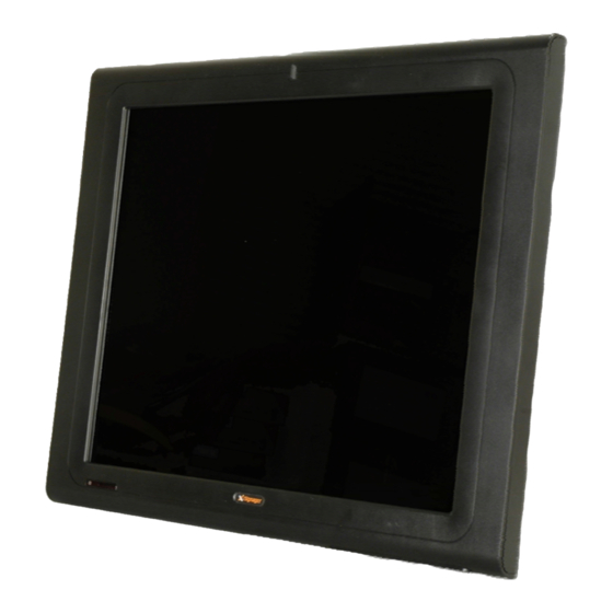
1.5 System Overview 1.5.1 Front View The front of the iSignager-LCD-S Series is a flat panel TFT LCD screen surrounded by an ABS/PC plastic frame. The iSignager-LCD-S Series also includes one infrared sensor and one LED on the front panel: Infrared Sensor This sensor receives the signal from the remote control. -
Page 12: Bottom Panel
Figure 1-1 shows the front view of iSignager-LCD-19S. Figure 1-1: iSignager-LCD-S Series Front View A control button panel (OSD) with the following control buttons is located horizontally on the bottom of the front frame of iSignager-LCD-S Series: Menu Right Down Left Refer to Chapter 3 for the detailed descriptions of each OSD function. -
Page 13: Rear View
Composite BNC connector CompactFlash® slot Figure 1-2 shows the bottom panel of the iSignager-LCD-19S digital signage display. Figure 1-2: iSignager-LCD-S Series Bottom Panel View 1.5.3 Rear View The rear panel features fan ventilation holes and four retention screw holes that support a VESA FDMI (MIS-D 100) wall-mounting bracket, a stand or an arm. -
Page 14: Physical Dimensions
Figure 1-3: iSignager-LCD-S Series Rear View 1.6 Physical Dimensions The following sections describe the physical dimensions for the iSignager-LCD-S Series. 1.6.1 General Physical Dimensions General physical dimensions for the iSignager-LCD-S Series are shown in Table 1-2. Model Width Height Depth... -
Page 15: Isignager-Lcd-15S Physical Dimensions
ISignager-LCD-S Series Digital Signage Display 1.6.2 iSignager-LCD-15S Physical Dimensions The physical dimensions of the iSignager-LCD-15S are shown in Figure 1-4. Figure 1-4: iSignager-LCD-15S Physical Dimensions (millimeters) Page 7... -
Page 16: Isignager-Lcd-17S Physical Dimensions
Series Digital Signage Display 1.6.3 iSignager-LCD-17S Physical Dimensions The physical dimensions of the iSignager-LCD-17S are shown in Figure 1-5. Figure 1-5: iSignager-LCD-17S Physical Dimensions (millimeters) Page 8... -
Page 17: Isignager-Lcd-19S Physical Dimensions
ISignager-LCD-S Series Digital Signage Display 1.6.4 iSignager-LCD-19S Physical Dimensions The physical dimensions of the iSignager-LCD-19S are shown in Figure 1-6. Figure 1-6: iSignager-LCD-19S Physical Dimensions (millimeters) Page 9... -
Page 18: Isignager-Lcd-W19S Physical Dimensions
Series Digital Signage Display 1.6.5 iSignager-LCD-W19S Physical Dimensions The physical dimensions of the iSignager-LCD-W19S are shown in Figure 1-7. Figure 1-7: iSignager-LCD-W19S Physical Dimensions (millimeters) Page 10... -
Page 19: Specifications
ISignager-LCD-S Series Digital Signage Display 1.7 Specifications Table 1-3 shows the iSignager-LCD-S Series specifications. iSignager-LCD-15S iSignager-LCD-19S Model iSignager-LCD-17S W19S LCD Size 15" 17" 19" 19” Max. Resolution 1024x768 1280x1024 1280x1024 1440x900 Brightness (cd/m2) Contrast 400:1 800:1 800:1 1000:1 LCD Color 262K 16.7M... -
Page 20: Lcd Specifications
Series Digital Signage Display IP Level IP 64 IP 64 IP 64 N/G Weight 3.2 kg 3.8 kg 4.4 kg Table 1-3: iSignager-LCD-S Series Specifications 1.8 LCD Specifications 1.8.1 iSignager-LCD-15S LCD Specifications Table 1-4 lists the LCD specifications of the iSignager-LCD-15S. -
Page 21: Isignager-Lcd-17S Lcd Specifications
ISignager-LCD-S Series Digital Signage Display 1.8.2 iSignager-LCD-17S LCD Specifications Table 1-5 lists the LCD specifications of the iSignager-LCD-17S. Model iSignager-LCD-17S 17” Size AUO/M170EG01 MFR/Model SXGA (1280 x 1024) Resolution 337.9 x 270.3 Active Area (mm) 0.264 Pixel Pitch (mm) 16.7M... -
Page 22: Isignager-Lcd-19S Lcd Specifications
Series Digital Signage Display 1.8.3 iSignager-LCD-19S LCD Specifications Table 1-6 lists the LCD specifications of the iSignager-LCD-19S. Model iSignager-LCD-19S 19” Size AUO/M190EG02 MFR/Model SXGA (1280 x 1024) Resolution 376.32 x 301.06 Active Area (mm) 0.294 Pixel Pitch (mm) 16.7M... -
Page 23: Isignager-Lcd-W19S Lcd Specifications
ISignager-LCD-S Series Digital Signage Display 1.8.4 iSignager-LCD-W19S LCD Specifications The table below lists the widescreen LCD specifications of the iSignager-LCD-W19S. Model iSignager-LCD-W19S 19” Size SVA-NEC/SVA190WX1-05TB MFR/Model WXGA+ (1440 x 900) Resolution 408.24 x 255.15 Active Area (mm) 0.285 Pixel Pitch (mm) 16.7M... -
Page 24: Power Adapters
Series Digital Signage Display 1.9 Power Adapters All iSignager-LCD-S Series comes with a 60W AC/DC adapter. Table 1-8 lists the AC/DC power adapter specifications. Power 60 Watt AC/DC Adapter Output Voltage 12 V Input Voltage Range 90-264 V AC... -
Page 25: Packing List
ISignager-LCD-S Series Digital Signage Display 1.10 Packing List The iSignager-LCD-S Series is shipped with the following components. Should there be any missing parts or defects in the package, please contact IEI immediately. Quantity Item Image iSignager-LCD-S Series AC power adaptor Power cord 1GB demo CompactFlash®... -
Page 26: Before Start
1.11 Before Start 1.11.1 Choose Mass Storage Device - CF Card or HDD Before using the iSignager-LCD-S Series, choose either a CF card or a HDD as the mass storage device for the iSignager-LCD-S Series. Device settings and display content are saved in the mass storage device. -
Page 27: Supported Formats
The supported formats are listed in Table 1-9. Detailed descriptions of each format can be found in Appendix B. NOTE: The video in .mpe format can be run by iSignager-LCD-S Series, but the video length information will not be available. iSignager-LCD-S Series Supported Formats Video MPEG-1 VCD format (1.15 Mbps CBR) [.mpg, .mpe, .mpeg, .dat, .m1v]... -
Page 28: Installation
Series Digital Signage Display Chapter Installation Page 20... -
Page 29: Hardware Installation
Connect audio and video input to the player (if available). Step 2: To transfer player settings or sequences to the player via the network, connect the iSignager-LCD-S Series to the same LAN of the PC via an Ethernet cable (optional step). Step 3: Connect the player to the power supply. -
Page 30: Figure 2-1: Format The Hdd Via Ide-Usb Cable
HDD. Disconnect the HDD from the computer. Step 3: Remove the plastic back cover of the iSignager-LCD-S Series. The plastic back cover is secured to the chassis with few retention screws. Remove the retention screws (Figure 2-2) and lift the back cover off the iSignager-LCD-S Series. -
Page 31: Figure 2-3: Isignager-Lcd-15S Aluminum Back Cover Retention Screws
ISignager-LCD-S Series Digital Signage Display Figure 2-3: iSignager-LCD-15S Aluminum Back Cover Retention Screws Figure 2-4: iSignager-LCD-17S Aluminum Back Cover Retention Screws Figure 2-5: iSignager-LCD-19S Aluminum Back Cover Retention Screws Page 23... -
Page 32: Figure 2-6: Isignager-Lcd-W19S Aluminum Back Cover Retention Screws
Series Digital Signage Display Figure 2-6: iSignager-LCD-W19S Aluminum Back Cover Retention Screws Step 5: Remove the HDD brackets (Figure 2-7) by removing the four HDD bracket retention screws. Figure 2-7: HDD Brackets Page 24... -
Page 33: Figure 2-8: Secure Hdd To The Brackets
2-8). Figure 2-8: Secure HDD to the Brackets Step 7: Install the HDD into the iSignager-LCD-S Series. Insert the HDD to the IDE connector on the board and secure the HDD to the board with four retention screws (Figure 2-9). -
Page 34: Mounting The Isignager-Lcd-S Series
Series Digital Signage Display 2.2 Mounting the iSignager-LCD-S Series The iSignager-LCD-S Series can be mounted on a wall, stand or arm. The mounting methods are described below. CAUTION: When mounting the iSignager-LCD-S Series take care to tighten the retention screws or bolts until fully secure, but do not over tighten. -
Page 35: Figure 2-10: Wall-Mounting Bracket
ISignager-LCD-S Series Digital Signage Display Step 3: Drill four pilot holes at the marked locations on the wall for the bracket retention screws. Step 4: Align the wall-mounting bracket screw holes with the pilot holes. Step 5: Secure the mounting-bracket to the wall by inserting the retention screws into the four pilot holes and tightening them (Figure 2-10). -
Page 36: Stand Installation
The iSignager-LCD-S Series has Video Electronics Standards Association (VESA) standard mounting holes tapped into the rear panel. The stand mounting plate has a matching VESA hole pattern. To mount the iSignager-LCD-S Series onto a stand, please follow the steps below. -
Page 37: Arm Mounting
ISignager-LCD-S Series Digital Signage Display Step 2: Secure the iSignager-LCD-S Series to the stand with the supplied retention screws (Figure 2-12).Step 0: Figure 2-12: Stand Mounting 2.2.4 Arm Mounting The iSignager-LCD-S Series is VESA (Video Electronics Standards Association) compliant and can be mounted on an arm with a 100 mm interface pad. To mount the iSignager-LCD-S Series on an arm, please follow the steps below. -
Page 38: Figure 2-13: Arm Mounting Retention Screw Holes
Figure 2-13. Figure 2-13: Arm Mounting Retention Screw Holes Step 4: Secure the iSignager-LCD-S Series to the interface pad by inserting four retention screws through the bottom of the mounting arm interface pad and into the iSignager-LCD-S Series. -
Page 39: On-Screen-Display (Osd) Controls
ISignager-LCD-S Series Digital Signage Display Chapter On-Screen-Display (OSD) Controls Page 31... -
Page 40: User Mode Osd Structure
3.1 User Mode OSD Structure 3.1.1 OSD Buttons There are several on-screen-display (OSD) control buttons oriented horizontally on the bottom of the iSignager-LCD-S Series front panel. Figure 3-1 shows a typical arrangement of OSD controls. Figure 3-1: OSD Control Buttons Up Button Press this button to scroll up or to switch from one selected item to another. -
Page 41: Using The Osd
ISignager-LCD-S Series Digital Signage Display 3.2 Using the OSD The OSD menu options are shown in Figure 3-2. The OSD menu options are described below. Figure 3-2: OSD Menu Option Description Value Volume Adjust the volume of the iSignager-LCD-S 0 ~ 8 Series. -
Page 42: Remote Control
Series Digital Signage Display 3.3 Remote Control The iSignager-LCD-S Series comes with a remote control for easy configuration of OSD settings. Figure 3-3 shows the remote control and its function keys. Figure 3-3: Remote Control LCD On/Off. Press this button to turn the LCD monitor on or off. -
Page 43: A Video, Audio And Graphic Formats
ISignager-LCD-S Series Digital Signage Display Appendix Video, Audio and Graphic Formats Page 35... -
Page 44: Overview Of Video Formats
Series Digital Signage Display A.1 Overview of Video Formats A.1.1 MPEG-1 MPEG-1 is a standard used to compress audio and video (AV) digital data. MPEG-1 defines a group of AV coding standards agreed upon by MPEG (Moving Picture Experts Group). -
Page 45: Dvd .Iso
ISignager-LCD-S Series Digital Signage Display XviD is a free and open source MPEG-4 video codec. XviD features MPEG-4 Advanced Simple Profile features such as b-frames, global and quarter pixel motion compensation, lumi masking, trellis quantization, and H.263, MPEG and custom quantization matrices. -
Page 46: Overview Of Audio Formats
Series Digital Signage Display A.2 Overview of Audio Formats A.2.1 Dolby® Digital Dolby® Digital, or AC-3, is the common version containing 6 total channels of sound, with 5 channels for normal-range speakers (right front, center, left front, right rear and left rear) and one channel for the LFE, or subwoofer. -
Page 47: Overview Of Graphic Formats
ISignager-LCD-S Series Digital Signage Display A.3 Overview of Graphic Formats A.3.1 JPEG and JPG JPEG (pronounced as jay-peg) is a commonly used standard method of lossy compression for photographic images. JPEG is designed for compressing full-color or gray-scale images of natural, real-world scenes. It works well on photographs, naturalistic artwork, and similar material;... -
Page 48: Standard Definition (Sd) Introduction
Series Digital Signage Display BMP, reduces file size by reducing the number of colors. PNG can also be 24-bit true-color and maintain all the original image information, but file sizes are large. A.4 Standard Definition (SD) Introduction A.4.1 SDTV Standard-definition television or SDTV refers to television systems that have a lower resolution than HDTV systems. -
Page 49: Notation
ISignager-LCD-S Series Digital Signage Display A.5.1 Notation In the context of HDTV, the formats of the broadcasts are referred to using a notation describing: 720p60 720: The number of lines in the display resolution. P: Progressive frames (p) or interlaced fields (i). -
Page 50: B Check And Modify The Player Status By Serial Port
Series Digital Signage Display Appendix Check and Modify the Player Status by Serial Port Page 42... -
Page 51: Check And Modify The Isignager-Lcd-S Series Status By Serial Port
ISignager-LCD-S Series Digital Signage Display B.1 Check and Modify the iSignager-LCD-S Series Status by Serial Port Follow the following steps and command to check and modify the iSignager-LCD-S Series status by RS-232 serial port. ® ® Step 1: In Windows... - Page 52 Series Digital Signage Display Step 3: Connect RS-232 cable to COM1 of iSignager-LCD-S Series: vick[/]# run vick[/]# cd /bin Step 4: Display Playerinfo function: vick[/bin]# ./playerinfo BINFMT_FLAT: Loading file: ./playerinfo Usage: ./playerinfo -i: To display all information ./playerinfo -sh hostname: To change PC host name ./playerinfo -ch hostname: To change client host name...
- Page 53 ISignager-LCD-S Series Digital Signage Display ./playerinfo -pstop: To stop playlist ./playerinfo -pstart: To start playlist ./playerinfo -cstart: To restart client ./playerinfo -time <val>: To change time : To display wireless info ./playerinfo -wal : To reboot system ./playerinfo -reboot Step 5: Examples: Example 1.1 Use command playerinfo-i and show the information of the player...
- Page 54 Series Digital Signage Display Dhcp : disable Display Device : VGA 1360x768 60 Apps Version : 200 WIFI : BINFMT_FLAT: Loading file: /new/part1/bin/playerinfo Client ra0 Ip : 192.168.10.3 Access Point : 00:13:46:87:EA:02 Encryption key : 132-3334-3536-3738-3930-6162-63 ESSID : "iei_sw2"...
- Page 55 ISignager-LCD-S Series Digital Signage Display Changing server IP Done Example 6. Set client IP to client system vick[/bin]# ./playerinfo -ci 10.10.10.74 BINFMT_FLAT: Loading file: ./playerinfo Changing client IP 10.10.10.74 eth0: link up, 100Mbps, full-duplex, lpa 0x45E1 vick[/bin]# interface < eth0 > is up and running ================================================== the systems IP address is :10.10.10.74...
- Page 56 Series Digital Signage Display Example 7. Set DHCP action vick[/bin]# ./playerinfo -d 1 BINFMT_FLAT: Loading file: ./playerinfo Changing dhcp.txt Done Example 8. Stop playing vick[/bin]# ./playerinfo -pstop BINFMT_FLAT: Loading file: ./playerinfo killall: pictureplayer: no process killed killall: play0: no process killed...
- Page 57 ISignager-LCD-S Series Digital Signage Display /new/playlist5.txt***********************Fading: disabled Alpha0: 255 Alpha1: 255 Running check iEi WCODE 1 0x05 0x02 iEi RCODE 1 0x05 0x02 Example 10. Restart client connect vick[/bin]# ./playerinfo -cstart BINFMT_FLAT: Loading file: ./playerinfo vick[/bin]# interface < eth0 > is up and running ================================================== the systems ip address is :10.10.10.74...
-
Page 58: Successful Message-Lan Connection
Series Digital Signage Display BINFMT_FLAT: Loading file: ./playerinfo Setting the date Sat Jul 22 11:14:00 MDT 2006 Example 12. Reboot the player vick[/bin]# ./playerinfo -reboot Step 6: Use the following command to modify LAN settings: ifconfig eth0 IP : set client IP value ifconfig eth0 netmask : set client mask e.g. -
Page 59: Successful Message-Wifi Connection
ISignager-LCD-S Series Digital Signage Display interface < eth0 > is up and running ================================================== the systems ip address is :192.168.1.10 connecting to windows server....windows server ip address is : 192.168.1.5 windows server hostname is : RD-VICKWU-NB error status-w: Contact iEi code=0x05 failed... - Page 60 Series Digital Signage Display WiFi IP { 10.10.88.100 } WiFi Encryption Enable { Y } WiFi Key type { open } WiFi cipher type { WEP } WiFi key index { 1 } WiFi Key Length { 128 }...
-
Page 61: Checking Connection
To check if the specific IP connection exists in the client side, check in a Hyper Terminal session of the iSignager-LCD-S Series. To create a Hyper Terminal session, please refer to Section B.1. In Hyper Terminal session, type “ping” followed by the LAN IP or WLAN IP, e,g. -
Page 62: Check The Status In The Player Manager
On-Line, Off-Line or Playing. B.3 iSignager-LCD-S Series Network Behavior The user can setup LAN and Wifi settings in the iSignager-LCD-S Series at the same time. However, the iSignager-LCD-S Series takes LAN as the first priority by default when booting up. If the LAN is successfully activated, the iSignager-LCD-S Series does not activate the Wifi settings.
Need help?
Do you have a question about the iSignager-LCD-S Series and is the answer not in the manual?
Questions and answers