
Related Manuals for Intek HR-2040


Summary of Contents for Intek HR-2040
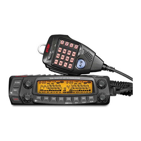
- Page 1 AMATEUR RADIO DUAL BAND MOBILE TRANSCEIVER 144-146 MHz VHF FM 50W 430-440 MHz UHF FM 40W PC PROGRAMMABLE OWNER'S MANUAL...
- Page 2 INTEK S.R.L. declines any responsibility concerning any modification of the product, made by the user or by a third party, after delivery of the product.
-
Page 3: General Information
The use of VHF and UHF FM transceivers is subject to the regulations applied in the country where the product has to be used. As regulations are usually subject to possible modifications, please check the current regulations in your country with your dealer or local supplier. INTEK does not take any responsibility for illegal use and operation of this product not in accordance with the regulation of the country where the product is used. - Page 4 The use of VHF and UHF FM transceivers is subject to the regulations applied in the country where the product has to be used. As regulations are usually subject to possible modifications, please check the current regulations in your country with your dealer or local supplier. INTEK does not take any responsibility for illegal use and operation of this product not in accordance with the regulation of the country where the product is used.
-
Page 5: Table Of Contents
CONTENTS New and Innovative Features ...........1 High/Mid/Low Power Switch ..........13 Frequency Range ..............1 Frequency Reverse ...............13 Band-width Selection ............13 Supplied Accessories / Optional Accessories ......2 Supplied Accessories ..............2 HOME Channel ..............13 Optional Accessories ..............2 Hyper Memory Channel ............13 Initial Installation ...............3 Dual Watch................14 Mobile installation ..............3 Emergency Alarm ..............14... - Page 6 CONTENTS Squelch Mode Setup .............20 AM Function ................29 Compander ................21 Automatic AM function ............29 VHF External speaker port ............29 Scrambler Setup ..............21 Tone Bust (Pilot Frequency) ..........21 BEEP Volume control ............30 Keypad Mode Setup .............22 Talk Around ................30 Keypad Lockout ..............23 Microphone Speaker ............30 TX OFF (PTT Lockout) ............23 Password Function ...............30...
-
Page 7: New And Innovative Features
New and Innovative Features HR-2040 Mobile Radio has nice housing, stoutness & stability, advanced and reliable functions, perfect & valuable. This amateur mobile radio especially designs for drivers and it pursues company philosophy of innovation and practicality. More functions as follows: 758 memory channels, full duplex operation with independent volume and squelch controls. -
Page 8: Supplied Accessories / Optional Accessories
Supplied Accessories / Optional Accessories SUPPLIED ACCESSORIES After carefully unpacking the transceiver, identify the items listed in the table below. We suggest you keep the box and packaging. Transceiver Microphone (QHM-05) Mobile Mounting DC Power Cable with Hardware Kit for Bracket S-Washer (with DTMF keyboard) Black screws... -
Page 9: Initial Installation
Initial Installation Determine the appropriate angle of the transceiver, using the 3 MOBILE INSTALLATION screw hole positions on the side of the mounting bracket. To install the transceiver, select a safe, convenient location inside your vehicle that minimizes danger to your passengers and yourself while the vehicle is in motion. -
Page 10: Dc Power Cable Connection
Initial Installation Reconnect any wiring removed from the negative terminal. DC POWER CABLE CONNECTION Locate the power input connector as close to the transceiver as possible. NOTE MOBILE OPERATION Black The vehicle battery must have a nominal rating of 12V. Never connect the transceiver to a 24V battery. - Page 11 Initial Installation FIXED STATION OPERATION In order to use this transceiver for fixed station operation, you Regulated Power Supply will need a separate 13.8V DC power supply (not included) , power (SPA-8230) supply (SPA-8230) as optional accessories. Please contact local dealer to require.
-
Page 12: Antenna Connection
Initial Installation REPLACING FUSES an impedance other than 50Ω reduces the efficiency of the antenna system and can cause interference to nearby broadcast television If the fuse blows, determine the cause, then correct the problem. receivers, radio receivers, and other electronic equipment. After the problem is resolved, replace the fuse. -
Page 13: Accessories Connections
Please use the free software for programming. Free download at : For voice communications, connect a microphone equipped with http://www.intek-radios.com an 8-pin modular plug into the modular socket on the front of the main unit. Press firmly on the plug until the locking tab clicks. Attach the supplied microphone hanger in an appropriate location using the screws included in the screw set. -
Page 14: Getting Acquainted
Getting Acquainted FRONT PANEL Function set Key In standby , press this key to enter function menu Power Press it to power On /Off the transceiver In standby press it to change H/L power on Left [LOW] Key selected channel. Long press it to turn ON/OFF Frequency Reverse function. -
Page 15: Rear Panel
Getting Acquainted REAR PANEL NO. INDICATOR FUNCTION Displays the channel number and Menu number. Appears when current channel priority channel Appears when current channel is set Scan Skip Appears when current channel has CTCSS Encode Appears when current channel has CTCSS Decode Appears when the Offset function is ON Appears while transmitting. -
Page 16: Microphone
Getting Acquainted MICROPHONE NO. KEY FUNCTION Increase frequency ,channel number or setting value. Decrease frequency, channel number or DOWN setting value. Press PTT (Push-To-Talk) key to transmit. Number Key Input VFO frequency or DTMF dial out etc. A/B band Choose left band or right band as Main band Band indicator The indicator light on for Main band. -
Page 17: Basic Operations
; the LCD displays "WELCOME INTEK ", then counterclock-wise to decrease frequency. -
Page 18: Switch Between Main Band And Sub Band
Basic Operations correspondent selector knob, the channel number flashes in this This transceiver can be set working on 2 UHF bands or 2 VHF bands. NOTE situation, the channel number will increase 10 channels by each gear of selector knob. Press microphone [ UP/DOWN ] key also able to adjust RECEIVING the channel. -
Page 19: Shortcut Operations
Shortcut Operations SQUELCH LEVEL SETUP In channel mode, this operation is for temporary use only NOTE This function is used to setup the strength of receiving signal, when the stren gth reach a certain level, the calling can be heard, otherwise, the FREQUENCY REVERSE transceiver will keep mute. -
Page 20: Dual Watch
Shortcut Operations for over 0.5 second, the radio prompts DUAL WATCH "DU DU", and LCD displays "SKIP", and now In standby, hold key for over 0.5 second to enter Dual Watch the current channel is Scan Skip. mode. The radio will scan the channel in every 5 seconds. When the radio receives match signal, it pause scanning until the signaling disappear. -
Page 21: Channel Delete
Shortcut Operations storage has data , the LCD will display the frequency, otherwise will display----------) Press key, the LCD displays MEN-IN, channel copy completed. CHANNEL DELETE I n s t a n d b y, h o l d k e y u n t i l t h e transceiver prompt DU, and channel number flashes. -
Page 22: General Setting
General Setting Operating steps of Function Menu. Press key to enter function menu. Turn the Main band selector knob to Press key to enter function menu. choose No. 02 menu; the LCD displays Turn the Main band selector knob to choose wanted function. "ARS". -
Page 23: Vfo Band Lockout
General Setting CPU CLOCK FREQUENCY CHANGE This function is auto-hidden in channel mode NOTE When any harmonic or image frequency in the CPU clock disturbs the working frequency, turn on this function to cut the disturbing. VFO BAND LOCKOUT Press key to enter function menu. -
Page 24: 5-Tone Encode Select
General Setting Switch the Main band selector knob to choose wanted value. 5-TONE ENCODE SELECT DTMF: means DTMF signaling is added. Press key to enter function menu. 2TONE: means DTMF signaling is added. Turn the Main band selector knob to choose No. -
Page 25: Ctcss Decode Setup
General Setting Press the Main band selector knob or key to store value and SUB BAND DISPLAY SETUP back to function menu. Press key or hold selector knob for Press key to enter function menu. over 0.5 second to store setup and exit. Turn the Main band selector knob to choose No. -
Page 26: Dtmf Encode Transmitting Time
General Setting When the selected group is empty, the DTMF ENCODE TRANSMITTING TIME LCD displays "------" Press key to enter function menu. Press the selector knob to enter the DTMF signaling edit. The LCD Turn the Main band selector knob to display "-- -- -- -- -- --", the last character flashes choose No 14 menu. -
Page 27: Compander
General Setting Press the Main band selector knob or key to store value and Press key to enter function menu. back to function menu. Press key or hold selector knob for Turn the Main band selector knob to over 0.5 second to store setup and exit. choose No 18 menu. -
Page 28: Keypad Mode Setup
General Setting Press the Main band selector knob or key to store value and LCD displays DT means DTMF, displays 5T means 5-TONE, back to function menu. Press key or hold selector knob for over displays 2T means 2-TONE. 0.5 second to store setup and exit. Right band long press: Talk Around. -
Page 29: Keypad Lockout
General Setting Switch the Main band selector knob to choose wanted mode. time. SCAN direction can be changed by corresponding channel selector knob. Note:To enable this function, the BAND R, lock the right band PTT. Only able to transmit by left band. channel shall be programmed with CTCSS/DCS decode. -
Page 30: Sub Band Mute Setup
General Setting Switch the Main band selector knob to choose wanted value. EDIT CHANNEL NAME ON: Function enabled. TX and RX frequencies will be After edit a name for a channel, if the display mode is "channel name", exchanged; CTCSS and DCS signaling will be exchanged if the LCD displays the name edited in this menu. -
Page 31: Microphone Pa,Pb, Pc,Pd Key Setup
General Setting Switch the Main Band selector knob to choose wanted value. S-5: Able to hear the calling when the power meter reach 4 bar. MANUAL: Auto Storage function is enabled. S-9: Able to hear the calling when the power meter reach 8 bar. AUTO: Auto Storage function is disabled. -
Page 32: Priority Channel Scan
General Setting TIME: it pauses 5s once scanning a OFFSET FREQUENCY SETUP matching signal, then resume scan. Press key to enter function menu. BUSY: it pauses once scanning a matching signal, then resume scan Turn the Main band selector knob to after the signal disappeared for 2 seconds. -
Page 33: Busy Channel Lockout
General Setting 5-TONE SELF ID ENQUIRY BUSY CHANNEL LOCKOUT When this function is enabled, the transmission is not possible on a busy Press key to enter function menu. channel, to avoid disturbing other transceiver using same frequency. Switch the selector knob to choose No 40 Once the channel is busy and you press PTT, the transceiver will beep as function. -
Page 34: Vfo Frequency Linkage
General Setting VFO FREQUENCY LINKAGE CROSS BAND REPEAT When this function is enable, any adjustment of VFO frequency, Set the left band and right band as VHF 144-146 MHz (136-174 MHz) will bring same frequency change to both bands. Adjust one gear, the and UHF 430-430 MHz (400-470 MHz) (*) then turn ON this function to enable Cross Band repeater function. -
Page 35: Keypad Backlight Brightness
General Setting Switch the Main band selector knob to choose wanted value. KEYPAD BACKLIGHT BRIGHTNESS OFF: AM function is disabled. ON: AM function is enabled. Press key to enter function menu. Press the Main band selector knob or key to store value and Turn the Main band selector knob to back to function menu. -
Page 36: Beep Volume Control
General Setting 5. Press the Main band selector knob or key to store value Switch the Main band selector knob to choose wanted value. and back to function menu. INT: Internal speaker, VHF and UHF bands share one speaker. Press key or hold selector knob for over 0.5 second to EXT: External speaker. -
Page 37: Microphone Operation
Microphone Operation when the LCD displays"-", means minus offset. This function is valid only when current channel is set with offset frequency. NOTE DOWN Add or delete priority channel: In Numeric Keys channel mode, press the key programmed UP/DOWN lock key as PRI function to set priority channel;... - Page 38 Microphone Operation now adjust selector knob or microphone [ UP/DOWN ] key to select to transmit selected tone burst. This function is use to wake sleeping the desired channel. repeater. REV: In standby, press the key programmed CALL OUT: Calling, in standby, press the key programmed as "CALL as "REV"...
-
Page 39: Resume Factory Default
Resume Factory Default RESUME FACTORY DEFAULT If your radio seems to be malfunctioning because of wrong operation or setup, this function will resume all setup and channel to factory default. Hold the right band while power ON the radio; all channnels and function setup will resume to factory default. -
Page 40: Programing Software Installing And Starting (In Windows Xp System)
Programming Software Installing and Starting (in windows XP system) Download the free programming software from www.intek-radios.com, double click the setup.exe then follow the installing instructions. INSTALL USB CABLE DRIVERS Click "Start" menu on your PC then select "All Programs" menu and click the icon "USB To Com Port"... -
Page 41: Maintenance
Maintenance DEFAULT FACTORY RESUME TROUBLE SHOOTING HR-2040 Possible Causes and Potential Solutions Problem Left band Right band + and - polarities of power connection are (a) Power is ON, nothing reversed. Connect red lead to plus terminal VFO frequency 145.15 MHz 435.15 MHz... -
Page 42: Specification
Specifications SPECIFICATIONS General Frequency VHF 144-145.9975 MHz (136-174 MHz (*)) / UHF 430-439.9950 MHz (400-490 MHz (*)) 118-136 MHz AM Air Band (RX only) Channels Channel spacing 25 KHz (Wide) / 20 KHz (Middle) / 12.5 KHz (Narrow) Frequency Step 2.5 / 5 / 6.25 / 8.33 / 10 / 12.5 / 15 / 20 / 25 / 30 / 50 KHz DC input voltage 13.8 VDC +/- 15%... -
Page 43: Attached Chart
Attached Chart 1024 GROUPS DCS CODE 51 GROUPS CTCSS TONE FREQUENCY (Hz) 62.5 77.0 91.5 107.2 127.3 151.4 167.9 183.5 199.5 225.7 254.1 Self 67.0 79.7 94.8 110.9 131.8 156.7 171.3 186.2 203.5 229.1 Defined 69.3 82.5 97.4 114.8 136.5 159.8 173.8 189.9 206.5 233.6 71.9 85.4 100.0 118.8 141.3 162.2 177.3 192.8 210.7 241.8 74.4... - Page 44 Attached Chart...
-
Page 45: Declaration Of Conformity
(to EC Directive 2006/95, 2004/108, 1999/5) DECLARATION OF CONFORMITY With the present declaration, we certify that the following products : INTEK HR-2040 comply with all the technical regulations applicable to the above mentioned products in accordance with the EC Directives 2006/95/EC, 2004/108/EC, 1999/5/EC. -
Page 46: Notes
Notes... - Page 47 Notes...
Need help?
Do you have a question about the HR-2040 and is the answer not in the manual?
Questions and answers