
Related Manuals for Intek HR-200S


Summary of Contents for Intek HR-200S
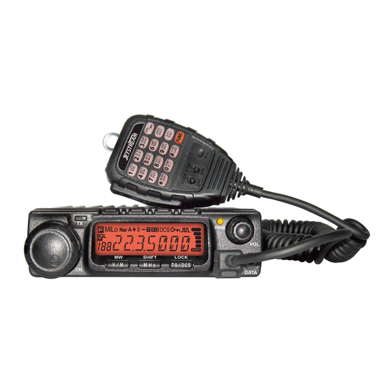
- Page 1 AMATEUR RADIO MOBILE TRANSCEIVER 144-146 MHz VHF FM 60W PC PROGRAMMABLE AMATEUR RADIO MOBILE TRANSCEIVER 430-440 MHz UHF FM 45W PC PROGRAMMABLE OWNER'S MANUAL...
- Page 2 Any modification to the product, alteration of the internal circuit, of the external structure of the radio or any programming in violation of the current regulations will automatically void the product certification and your right to use the product. INTEK S.R.L. declines any responsibility concerning any modification of the product, made by the user or by a third party, after delivery of the product.
-
Page 3: General Information
The use of VHF and UHF FM transceivers is subject to the regulations applied in the country where the product has to be used. As regulations are usually subject to possible modifications, please check the current regulations in your country with your dealer or local supplier. INTEK does not take any responsibility for illegal use and operation of this product not in accordance with the regulation of the country where the product is used. - Page 4 The use of VHF and UHF FM transceivers is subject to the regulations applied in the country where the product has to be used. As regulations are usually subject to possible modifications, please check the current regulations in your country with your dealer or local supplier. INTEK does not take any responsibility for illegal use and operation of this product not in accordance with the regulation of the country where the product is used.
-
Page 5: Table Of Contents
CONTENTS ..........1 Transmitting Optional Signaling ............13 Channel Edit ..................13 Supplied Accessories/Optional Accessories .....2 Channel Delete ................13 Supplied Accessories............... 2 Shortcut Operations.............14 Optional Accessories ............... 2 Squelch Off/Squelch Off Momentary..........14 ..............3 Squelch Level Setup ................ 14 Mobile Installation ................3 DC Power Cable Connection ............ - Page 6 50 groups CTCSS Tone Frequency(Hz) .......... 34 Address List ..................26 1024 groups DCS Code..............34 Factory Default................. 26 Declarations of Conformity ..........36 Microphone Operation ............27 Declaration of Conformity HR-200S ..........36 Function Setup By Microphone Keypad........... 27 Declaration of Conformity HR-400S ..........36 Notes ..................37...
-
Page 7: New And Innovative Features
New and Innovative Features INTEK Mobile Radios has nice housing, stoutness & stability, advanced and reliable functions, perfect & valuable. This amateur mobile radio especially designs for drivers and it pursues company philosophy of innovation and practicality. More functions as follows: Display on a large LCD with adjustable brightness, convenient for nighttime use. -
Page 8: Supplied Accessories/Optional Accessories
Supplied Accessories/Optional Accessories Supplied Accessories After carefully unpacking the transceiver, identify the items listed in the table below. We suggest you keep the box and packaging. Transceiver Microphone Mobile Mounting DC Power Cable with Hardware Kit for Bracket Black screws Tapping screws (with DTMF keyboard) Bracket... -
Page 9: Mobile Installation
Initial Installation Determine the appropriate angle of the transceiver, using the 3 screw Mobile installation hole positions on the side of the mounting bracket. To install the transceiver, select a safe, convenient location inside your vehicle that minimizes danger to your passengers and yourself while the vehicle is in motion. -
Page 10: Dc Power Cable Connection
Initial Installation DC Power Cable Connection Locate the power input connector as close to the transceiver as possible. Mobile Operation The vehicle battery must have a nominal rating of 12V. Never connect the transceiver to a 24V battery. Be sure to use a 12V Black vehicle battery that has sufficient current capacity. - Page 11 Initial Installation Fixed Station Operation need a separate 13.8V DC power supply (not included), power supply ( SPA-8230) as optional accessories. Please contact local Regulated Power Supply dealer to require. (SPA-8230) The recommended current capacity of your power supply is 12A. Connect the DC power cable to the regulated DC power supply and ensure that the polarities are correct.
-
Page 12: Power Supply Voltage Display
Initial Installation Replacing Fuses If the fuse blows, determine the cause, then correct the problem. After the problem is resolved, replace the fuse. If newly installed fuses continue to blow, disconnect the power cable and contact your autho- rized dealer or an authorized service center for assistance. The range of displayed voltage is only from 7V to16V DC, because the displayed value is estimated, please use a voltmeter when a more precise reading is desired. -
Page 13: Accessories Connections
The wrong connecting way as the following picture. transceiver to your PC then using the optional programming cable (via Data socket ). Please use the free software for programming. Error www.intek-radios.com FSP-30 Ground Ask your dealer about purchasing the optional Programming Cable. -
Page 14: Front Panel
Getting Acquainted Front Panel Press key until key. NO. KEY FUN/SET V/M/MW Stores data into channels MHz/SHIFT Sets offset direction and offset frequency TS/DCS/LOCK Sets Keypad lock function Switches between HI, MID and LOW power CAL/ H/L transmission SQL/D Compander mode on/off Press NO. -
Page 15: Rear Panel
Getting Acquainted Rear Panel NO. KEY Squelch level. In channel mode. Indicates the channel number in channel mode. Decimal point Channel skip. Indicates the decimal point of frequency and the Decimal point scanning function. Indicates the frequency or memory name. Signal is being received or monitor. -
Page 16: Microphone
Getting Acquainted Microphone MIC Connector Diagram(in the front view of connector) NO. KEY Increase frequency ,channel number or setting value. DOWN Decrease frequency, channel number or setting value. Press the PTT (Push-TO-Talk) key to transmit. Number Key Input VFO frequency or DTMF dial out etc.. D T M F O N / Switches between DTMF dialing or function operating. -
Page 17: Working Mode
WORKING MODE (AMATEUR TRANSCEIVER OR PROFESSIONAL TRANSCEIVER) According to practical application,you can set the radio works as Amateur Transceiver mode or Professional Transceiver mode . There This mode shows only frequency are also 2 levels operation menu to set functions as you need. It is easy on the display. -
Page 18: Basic Operations
Basic Operations frequency in screen will be auto-hidden. In this status, turn selector Switching the Power On/Off PWR KEY knob or Microphone [ ] key will increase or decrease according to the option selected during frequency quickly by 1MHz step . installation Press the switch or turn the Under channel mode, you can change the current channel to the... -
Page 19: Transmitting Tone-Pulse
Basic Operations Please hold the microphone approximately 2.5-5.0cm from your lips, Channel Delete and then speak into the microphone in your normal speaking voice to Under channel mode, turn selector knob to select channel which get best timbre. you want to delete. Press and hold [PTT] key, LED lights RED and power intensity showed in Press key and... -
Page 20: Shortcut Operations
Shortcut Operations Turn selector knob or press Microphone [ ] key to Squelch OFF / Squelch OFF momentary change scan direction. key programmed as Squelch Off or Squelch Off Momentary to monitor the weak signal. Press any key except key to exit. Squelch Off: Press key to disable squelch ,press Channel Scan... -
Page 21: Ctcss Scan
Shortcut Operations When LCD appears iron, it means current channe can be set HIGH/MID/LOW Power Switch with DCS encode and decode together, turn selector knob or press Press key until LCD display iron, Microphone's [ ] to select desired DCS encode and decode. -
Page 22: Offset Direction And Offset Frequency Setup
Shortcut Operations Offset direction and Offset Frequency setup Keypad Lockout Avoiding unintentional operation, this function will lock main keys, all Repeater receives a signal(UP-LINK) on one frequency and re- transmits on another frequency(DOWN-LINK). The difference between keys except key are invalid. these two frequencies is called the offset frequency. -
Page 23: Transmitting Edited Dtmf Tones In The Auto-Dialer Memory
Shortcut Operations Turn selector knob to choose group you desired. Total:16 group,01-16. Press key to enter into editing of current group,press MIC's numeric keys to set your desired data. The display scrolls when the 7th digit is entered. The numbers 0-9, --, A-D, * and # can be stored up to a total of 23 digits. -
Page 24: General Setting
General Setting features such as ANI, PTT ID, group call, remotely stun,remotely kill, Press and hold key for over 2s to enter general setting menu. waken,...etc. The signalling edition must be done through programming Press to select the desired function option. software. -
Page 25: Sending 2-Tone Call
General Setting Press directly to transmit the pre-stored 5-Tone signaling. P r e s s k e y t o c h o o s e No.04 menu, LCD displays "5TON In 5Tone signaling mode,press for 2s until LCD displays XX","XX"indicates the group in the list. -
Page 26: High/Mid/Low Power Selection
General Setting HIGH/MID/LOW Selection Press and hold key for over 2s to enter general setting menu. Press and hold key for over 2s to enter general setting menu. Press key to choose No.06 menu, LCD displays "SPK--SQ". Press key to choose No.07 menu, LCD displaysîPOW--HIî. -
Page 27: Tx Off Setup
General Setting BU: Enable BCLO, Carrier lockout, transmitting is inhibited when TX OFF Setup current channel receives a matching carrier;press [PTT] to emit Disable this function,it is invalid to press PTT,current channel only error voice prompt and back to receiving status. works in RX mode. -
Page 28: Talk Around
General Setting Press key to choose No.14 Press key to choose No.12 menu, LCD displays "COMP--OFF". menu, LCD displays "REV--OF". Turn selector knob to select the desired Turn selector knob to select the desired setting. setting. ON:Enable compander ON:Enable Frequency Reverse OFF:Disable Frequency Reverse. -
Page 29: Radio's 5Tone Self Id Enquiry
General Setting menu, LCD displays "D--XXX" XXX is radio's DTMF SELF ID. TOT (Time-out timer) Press The time-out timer limits the amount of transmitting time. When you reach the time limit which has been programmed by your dealer, your Radio's 5TONE self ID enquiry transmission will be cut off. -
Page 30: Dtmf Transmitting Time
General Setting Press 1HOUR:Auto power off after 1h 2HOUR:Auto power off after 2h Press ,then turn selector knob also can select the desired OFF:Disable Auto power off squelch level. If the transceiver has set at higher squelch level,it may fail to hear Press the calling.If set at lower squelch level,the radio will be interfered. -
Page 31: Pilot Frequency
General Setting menu, LCD displays"LAMP--25" P r e s s k e y t o c h o o s e N o . 2 6 m e n u , L C D Turn selector knob to select the desired LCD backlight brightness displays "DSP--FR". -
Page 32: Address List
General Setting Address list Press and hold key for over 2s to You store desired ID and corresponding ID name in address list.The enter general setting menu. LCD displays ID corresponding name if radio received ANI calling and Press key to choose No.29 menu, LCD displays"RESTORE". -
Page 33: Microphone Operation
Microphone Operation DOWN Switches between VFO and channel mode In standby,press key to switch between channel mode and Frequency mode (VFO). Short Calling In standby,press to transmit the selected DTMF/2TONE/5TONE Numeric Keys in current channel. Transmi tt ing DTMF Cod e:In standby,press ,LCD displays DTMF ON/OFF Lock... -
Page 34: Scan Skip
Microphone Operation BU: Enable BCLO, Carrier lockout, transmitting is inhibited when When first bit of Exa byte in frequency displays "F",it current channel receives a matching carrier;press [PTT] to emit error indicates 5Tone function enable. voice prompt. This function can be temporarily used in channel mode. Once the RL: Enable BTLO, transmitting is inhibited when current channel radio is turned off or switched to another channel, the temporary receives a matching carrier but dis-matching CTCSS/DCS.press... -
Page 35: Tot (Time-Out Timer)
Microphone Operation TOT (Time-out timer) Talk Around By Talk Around function,you can directly communicate with other radios The time-out timer limits the amount of transmitting time. When you in your group in case the repeater is not activated or when you are out of reach the time limit which has been programmed by your dealer, your the repeater range. -
Page 36: Lcd Backlight
Microphone Operation HI:High Power MI:Middle Power LOW:Low Power Press number keys to exit and store. LCD Backlight In standby status,press , then press LCD displays"LAMP- XX" . Press [ ] to select desired backlight brightness(1-32 levels). -
Page 37: Xp System)
Install USB Cable Driver Program Click start menu in computer, under "ALL PROGRAMS" menu, choose and click "USB To Com port" on INTEK program, install "USB To Com port" driver by indication. Connect the optional USB Programming cable to USB port on PC anc connect the transceiver (see pic 1). -
Page 38: Maintenance
Maintenance Default Setting after Resetting (VHF) Trouble Shooting DCS encode Problem Possible Causes and Potential Solutions and decode + and - polarities of power connection (a) Power is on, nothing are reversed. Connect red lead to plus VFO frequency 145.00MHz DCS code 023N appears on Display. -
Page 39: Specifications
Specifications SPECIFICATIONS General Frequency VHF 144-145.9975 MHz (136-174 MHz) (*) (HR-200S) UHF 430-439.9950 MHz (400-490 MHz) (*) (HR-400S) Channels Channel spacing 25 KHz (Wide) / 20 KHz (Middle) / 12.5 KHz (Narrow) Frequency Step 5 / 6.25 / 8.33 / 10 / 12.5 / 15 / 20 / 25 / 30 / 50 KHz DC input voltage 13.8 VDC +/- 15%... -
Page 40: Attached Chart
Attached Chart 50 groups CTCSS Tone Frequency (Hz) 1024 groups DCS Code 67.0 79.7 94.8 110.9 131.8 156.7 171.3 186.2 203.5 229.1 69.3 82.5 97.4 114.8 136.5 159.8 173.8 189.9 206.5 233.6 71.9 85.4 100.0 118.8 141.3 162.2 177.3 192.8 210.7 241.8 74.4 88.5 103.5 123.0 146.2 165.5 179.9 196.6 218.1 250.3 77.0 91.5 107.2 127.3 151.4 167.9 183.5 199.5 225.7 254.1... - Page 41 Attached Chart N is positive code, I is negative code, total: 232groups.
-
Page 42: Declarations Of Conformity
Declarations of Conformity Declaration of Conformity HR-200S Declaration of Conformity HR-400S EC Certificate of Conformity EC Certificate of Conformity (to EC Directive 2006/95, 2004/108, 99/5) (to EC Directive 2006/95, 2004/108, 99/5) DECLARATION OF CONFORMITY DECLARATION OF CONFORMITY With the present declaration, we certify that the following products :... -
Page 43: Notes
Notes...
Need help?
Do you have a question about the HR-200S and is the answer not in the manual?
Questions and answers