
Related Manuals for Transition Networks SISTF101X-241-LRT


Summary of Contents for Transition Networks SISTF101X-241-LRT
-
Page 1: User Manual
4-port 10/100TX + 1 port 100FX Industrial Switch User Manual SISTF101X-241-LRT V1.00 Oct., 2010... -
Page 2: Fcc Warning
Transition Networks SISTF101X-241-LRT FCC Warning This Equipment has been tested and found to comply with the limits for a Class A digital device, pursuant to Part 15 of the FCC rules. These limits are designed to provide reasonable protection against harmful interference in a residential installation. This equipment generates, uses, and can radiate radio frequency energy. -
Page 3: Table Of Contents
Content FCC Warning ............ii CE Mark Warning..........ii Overview .............1 Introduction............... 1 High-Speed Transmissions ..........1 Dual Power Input............... 1 Flexible Mounting .............. 1 Advanced Protection ............1 Wide Operating Temperature ..........2 Easy Troubleshooting............2 Features ..............3 Technical Specification .......... - Page 4 Transition Networks SISTF101X-241-LRT Ports ............... 11 Cabling ..............13 Wiring the Power Inputs ......... 14 Wiring the Fault Alarm Contact ......15 Mounting Installation .........16 DIN-Rail Mounting ..........16 Wall Mount Plate Mounting ........18 Hardware Installation ........19 Installation Steps ............ 20 Troubleshooting ..........21...
-
Page 5: Overview
Transition Networks SISTF101X-241-LRT Overview Introduction The 4 10/100TX + 1 100FX Industrial Switch is a cost-effective solution and meets the high reliability requirements demanded by industrial applications. High-Speed Transmissions The 4 10/100TX + 1 100FX Industrial Switch provides you with Fiber port for your fiber optic cable to make a long-distance connection. -
Page 6: Wide Operating Temperature
Transition Networks SISTF101X-241-LRT Wide Operating Temperature The operating temperature of the 4 10/100TX + 1 100FX Industrial Switch supports the wide operating temperature in the range between -40 ~ 75 C. With such a wide range, you can use the 4 10/100TX + 1 100FX Industrial Switch in some of the harshest industrial environments that exist. -
Page 7: Features
Transition Networks SISTF101X-241-LRT Features Provides 4 x 10/100TX Mbps Ethernet ports Provides 1 SC/ST fiber optic port TX ports support full/half duplex flow control Supports MDI/MDI-X auto-crossover Supports surge (EFT) protection 3,000 V for power line Supports 6,000 V Ethernet ESD protection... -
Page 8: Technical Specification
Transition Networks SISTF101X-241-LRT Technical Specification The technical specifications of the Industrial Switch are listed as follows. Communications IEEE 802.3, 802.3u, 802.3x Compatibility 10/100Base-TX, 100FX Transmission Distance Multi-Mode Fiber 2KM (50/125 m ~ 62.5/125 m) Single-Mode Fiber 30KM (9/125 m) UTP/STP up to 100 meters... - Page 9 Transition Networks SISTF101X-241-LRT 2 x Unregulated +12 ~ 48 V Power Input Fault Output 1 Relay Output Mechanism Dimensions (WxHxD) 30 x 95 x 140 Enclosure IP30, Metal shell with solid mounting kits DIN rail, Wall Mount Mounting Protection 6,000 V...
- Page 10 Transition Networks SISTF101X-241-LRT CE EN61000-4-2 (ESD) CE EN61000-4-3 (RS) CE EN61000-4-4 (EFT) CE EN61000-4-5 (Surge) CE EN61000-4-6 (CS) CE EN61000-4-8 (Magnetic Field) CE EN61000-4-11 (Voltage DIP) CE EN61000-6-2 CE EN61000-6-4 IEC60068-2-32 Free Fall Shock IEC60068-2-27 IEC60068-2-6 Vibration 24-Hour Technical Support: 1-800-260-1312...
-
Page 11: Packing List
Transition Networks SISTF101X-241-LRT Packing List 1 x 4-port 10/100TX + 1-port 100FX Industrial Switch 1 x User manual 2 x Wall Mounting Bracket and Screws Compare the contents of the industrial switch with the standard checklist above. If any item is damaged or missing, please contact the local dealer for service. -
Page 12: Hardware Description
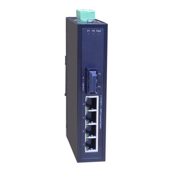
Transition Networks SISTF101X-241-LRT Hardware Description In this paragraph, we will introduce the Industrial switch’s hardware spec, port, cabling information, and wiring installation. Front Panel The Front Panel of the 4-port10/100TX + 1 port 100FX Industrial Switch is shown as follows. -
Page 13: Top View
Transition Networks SISTF101X-241-LRT Top View The top panel of the 4-port 10/100TX + 1 port 100FX Industrial Switch is equipped with one terminal block connector for the two power inputs and Fault Relay output. Top Panel of the 4-port 10/100TX + 1 port 100FX Industrial Switch... -
Page 14: Led Indicators
Transition Networks SISTF101X-241-LRT LED Indicators There are a few LEDs which display the power status and network status located on the front panel of the Industrial switch, each of them has its own specific meaning as the table below. Color... -
Page 15: Ports
Transition Networks SISTF101X-241-LRT Ports RJ-45 ports (Auto MDI/MDIX): The RJ-45 ports are auto-sensing for 10Base-T or 100Base-TX devices connections. Auto MDI/MDIX means that you can connect to another switch or workstation without changing straight through or crossover cabling. See figures as below for straight through and crossover cable schematic. - Page 16 Transition Networks SISTF101X-241-LRT Straight Through Cable Schematic Cross Over Cable Schematic Fiber Port The fiber connector can be worked in multi mode (2Km) or single mode (30Km). When you connect the fiber port to another one, please follow the figure below to connect accordingly.
-
Page 17: Cabling
Transition Networks SISTF101X-241-LRT ATTENTION This is a Class 1 Laser/LED product. Don’t stare into the Laser/LED Beam. Cabling Use four twisted-pair, Category 5 cabling for RJ-45 port connection. The cable between the switch and the link partner (switch, hub, workstation, etc.) must be less than 100 meters (328 ft.) long. -
Page 18: Wiring The Power Inputs
Transition Networks SISTF101X-241-LRT Wiring the Power Inputs Please follow the steps below to insert the power wires. 1. Insert the positive and negative wires into the V+ and V- contacts on the terminal block connector. 2. Tighten the wire-clamp screws to prevent the wires from coming loose. -
Page 19: Wiring The Fault Alarm Contact
Transition Networks SISTF101X-241-LRT Wiring the Fault Alarm Contact The fault alarm contact is in the middle of terminal block connector as the picture shows below. Inserting the wires, it will detect the fault status which the power is failure or port link failure (for managed model) and form an open circuit. -
Page 20: Mounting Installation
Transition Networks SISTF101X-241-LRT Mounting Installation DIN-Rail Mounting The DIN-Rail is screwed on the industrial switch at the factory. If the DIN-Rail is not screwed on the industrial switch, please see the following figure to screw the DIN-Rail on the switch. Follow the steps below to hang the industrial switch. - Page 21 Transition Networks SISTF101X-241-LRT Insert the top of DIN-Rail into the track. Then, lightly push the button of DIN-Rail into the track. Check the DIN-Rail is tightly on the track. To remove the industrial switch from the track, reverse the steps above.
-
Page 22: Wall Mount Plate Mounting
Transition Networks SISTF101X-241-LRT Wall Mount Plate Mounting Follow the steps below to mount the industrial switch with wall mount plate. Remove the DIN-Rail from the industrial switch; loose the screws to remove the DIN-Rail. Place the wall mount plate on the top & bottom side of the industrial switch. -
Page 23: Hardware Installation
Transition Networks SISTF101X-241-LRT Hardware Installation Below is an illustration of some typical applications for the 4-port 10/100TX + 1 port 100FX Industrial Switch. 24-Hour Technical Support: 1-800-260-1312 International: 00-1-952-941-7600... -
Page 24: Installation Steps
Transition Networks SISTF101X-241-LRT Installation Steps Unpack the Industrial switch packing. Check the DIN-Rail is screwed on the Industrial switch. If the DIN-Rail is not screwed on the Industrial switch. Please refer to DIN-Rail Mounting section for DIN-Rail installation. If you want to wall mount the Industrial switch, then please refer to Wall Mount Plate Mounting section for wall mount plate installation. -
Page 25: Troubleshooting
Transition Networks SISTF101X-241-LRT Troubleshooting Verify that you are using the right power cord/adapter. Please don’t use the power adapter output higher than the power input of this switch or it may damage the switch. Select the proper UTP/STP cable to construct your network. Please check that you are using the right cable.
Need help?
Do you have a question about the SISTF101X-241-LRT and is the answer not in the manual?
Questions and answers