Table of Contents
Advertisement
Quick Links
Transition Networks
SISTP10x0‐3xx‐LRT Series
Industrial Unmanaged PoE/PoE+ GbE Switches
Quick Start Guide
The SISTP10x0‐3xx‐LRT series industrial unmanaged GbE switches are a plug‐and‐play Ethernet switches that
make an easy transition to Gigabit Ethernet. The SISTP10x0‐3xx‐LRT series consist of two PoE+ models:
SISTP1040‐342‐LRT and SISTP1040‐382‐LRT. See the Install Guide for Safety Warnings and Cautions, Ordering info,
features, pecs, front/back panel descriptions, installation and setup, grounding, power supply, LED,
troubleshooting, regulatory agency, warranty, and contact
information.
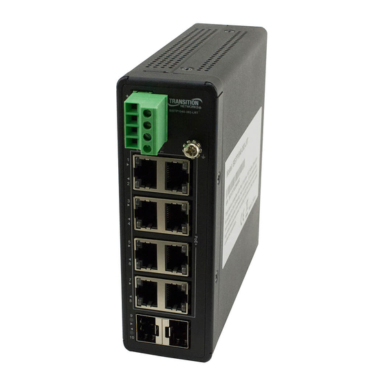
Front Panel
The SISTP1040‐382‐LRT front panel is shown right.
RESET Button
You can press the bottom panel RESET button to reboot the switch.
Installation and Setup
See the Install Guide for unpacking and package contents. The Switch
can be Wall mounted or installed on a DIN Rail. See the Install Guide.
Mounting the Switch on a Wall (Optional)
1. Attach the wall mounting plates to rear panel of chassis. Insert screws and tighten.
2. Install user‐supplied screws on the appropriate location on the wall.
3. Make sure the switch is attached securely to wall.
Mounting the Switch on a DIN Rail
1. Attach the DIN Rail mounting kit to the rear panel of the chassis. Insert screws and tighten.
2. Insert the upper lip of the DIN rail into the DIN‐rail mounting kit and press switch towards DIN rail until it
snaps into place.
3. Make sure that the switch is attached securely to DIN Rail.
Note: Make all cable connections and perform grounding before connecting to power.
Install and Connect SFPs via Fiber Optic Cable
For SFP ports use UL Listed Optional Transceiver products, Rated 3.3Vdc, Laser Class 1.
1. Prepare a fiber optic cable with appropriate connecter. Warning: Fiber optic port is a Class 1 laser device.
2. Remove a rubber plug and position the SFP at an SFP slot with the label facing correctly.
3. Carefully slide the SFP device into the slot, aligning it with the internal installation guides.
Ensure that the SFP device is firmly seated against the internal mating connector.
4. See the related SFP manual for operating information specific to your particular SFP model.
5. Connect the other end of the cable to the appropriate far end Ethernet port.
Note: After the cable is properly connected at both ends, the Switch LEDs should be functional.
33732 Rev. A
https://www.tranition.com
SISTP10x0‐3xx‐LRT Quick Start Guide
Page 1 of 2
Advertisement
Table of Contents

Related Manuals for Transition Networks SISTP1040-342-LRT


Summary of Contents for Transition Networks SISTP1040-342-LRT
- Page 1 Transition Networks SISTP10x0‐3xx‐LRT Quick Start Guide SISTP10x0‐3xx‐LRT Series Industrial Unmanaged PoE/PoE+ GbE Switches Quick Start Guide The SISTP10x0‐3xx‐LRT series industrial unmanaged GbE switches are a plug‐and‐play Ethernet switches that make an easy transition to Gigabit Ethernet. The SISTP10x0‐3xx‐LRT series consist of two PoE+ models: SISTP1040‐342‐LRT and SISTP1040‐382‐LRT. See the Install Guide for Safety Warnings and Cautions, Ordering info, features, pecs, front/back panel descriptions, installation and setup, grounding, power supply, LED, troubleshooting, regulatory agency, warranty, and contact information. Front Panel The SISTP1040‐382‐LRT front panel is shown right. RESET Button You can press the bottom panel RESET button to reboot the switch. Installation and Setup See the Install Guide for unpacking and package contents. The Switch can be Wall mounted or installed on a DIN Rail. See the Install Guide. Mounting the Switch on a Wall (Optional) 1. Attach the wall mounting plates to rear panel of chassis. Insert screws and tighten. 2. Install user‐supplied screws on the appropriate location on the wall. 3. Make sure the switch is attached securely to wall. Mounting the Switch on a DIN Rail 1. Attach the DIN Rail mounting kit to the rear panel of the chassis. Insert screws and tighten. 2. Insert the upper lip of the DIN rail into the DIN‐rail mounting kit and press switch towards DIN rail until it snaps into place. 3.
- Page 2 Transition Networks SISTP10x0‐3xx‐LRT Quick Start Guide Connect PoE+ Ports via TP Copper Cable The Switch also provides 10/100/1000Base‐T. Supported cabling: PoE per IEEE 802.3af PoE supports Cat 3 and Cat 5. PoE per IEEE 802.3at PoE+ supports Cat 5. 1. Prepare a twisted‐pair copper cable. 2. Connect one end of the cable to the Switch. 3. Connect the other end of the cable to a PD, such as a VoIP phone. Note: After the cable is properly connected at both ends, the Switch SYS LED should be functional. Grounding After the Switch is mounted and connected, the front panel grounding screw can be used for grounding. Grounding and wire routing help limit the effects of noise due to electromagnetic interference (EMI). Run the ground connection from the ground screw to the grounding surface before connecting devices. ATTENTION: This case must be earth grounded. No DC input may be earth grounded. Use Isolated Power Supply. Warning: Minimum input 52 VDC. Check polarity first! Warning and Caution ‐ Proper Installation and Operation (English): These devices are open‐type devices that are to be installed in an enclosure only accessible with the use of a tool, suitable for the environment. This equipment is suitable for use in Class I, Division 2, Groups A, B, C, and D or non‐hazardous locations only. WARNING – EXPLOSION HAZARD. DO NOT DISCONNECT WHILE THE CIRCUIT IS LIVE OR UNLESS THE AREA IS FREE OF IGNITIBLE CONCENTRATIONS. Avertissement et mise en garde ‐ Installation et fonctionnement corrects (français): Ces périphériques sont des périphériques de type ouvert qui doivent être installés dans un enceinte uniquement accessible à l'aide d'un outil, adapté à environnement. Cet équipement peut être utilisé dans la classe I, division 2, groupes A, B, C, et D ou des emplacements non dangereux seulement. AVERTISSEMENT ‐ RISQUE D'EXPLOSION. NE PAS SE DÉCONNECTER LORSQUE LE CIRCUIT EST VIVANT OU À MOINS QUE LA ZONE NE SOIT LIBRE DE CONCENTRATIONS IGNIFIABLES. Connecting to Power Industrial Power Supplies 25104 and 25105 are optional accessories (sold separately). See the Install Guide. After the Switch is mounted, connected, and grounded, use he Terminal Block’s DC Power Inputs P1 and P2. Warning: connect the wires to the terminal block before plugging power into the Switch product. V‐ 1. Insert the negative/positive DC wires into the and ...
Need help?
Do you have a question about the SISTP1040-342-LRT and is the answer not in the manual?
Questions and answers