Table of Contents
Advertisement
Quick Links
Advertisement
Table of Contents

Related Manuals for Transition Networks SISTP1040-382B-LRT


Summary of Contents for Transition Networks SISTP1040-382B-LRT
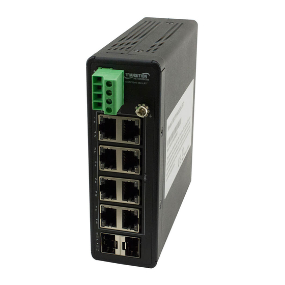
- Page 1 Transition Networks SISTP1040-382B-LRT Install Guide SISTP1040-382B-LRT Unmanaged Hardened Gigabit Ethernet PoE+ Switch with Low Voltage Input (8) 10/100/1000Base-T Ports + (2) 100/1000Base-X SFP Slots Install Guide 33806 Rev. B 33806 Rev. B https://www.transition.com Page 1 of 39...
-
Page 2: Safety Warnings And Cautions
Anyone using this product in such an application without express written consent of an officer of Transition Networks does so at their own risk and agrees to fully indemnify Transition Networks for any damages that may result from such use or sale. -
Page 3: Table Of Contents
Transition Networks SISTP1040-382B-LRT Install Guide Contents Safety Warnings and Cautions ..........................2 Record of Revisions ..............................2 1. Introduction ..............................5 Features / Benefits ..............................5 Ordering Information ............................... 5 About This Manual ..............................6 Related Manuals ..............................6 Specifications ................................6 Specifications ................................ - Page 4 Transition Networks SISTP1040-382B-LRT Install Guide User Information ..............................33 RoHS, WEEE, and Environmental Programs .......................33 Electrical Safety Warnings ..........................34 Warranty ................................35 Five-Year Limited Hardware Warranty ......................35 Box and Device Labels ............................36 Recording Model Information and System Information ..................37 Contact Us ................................38 33806 Rev.
-
Page 5: Introduction
Solar, Vehicle, or Factory systems, there are no standard power input requirements of 52 to 57 volts for PoE devices. The SISTP1040-382B-LRT uses booster technology to let you deploy the PoE switches in the power input range of 12 to 24 volts. It can still deliver up to 30 Watts on each PoE+ port. The two fiber uplink ports can also be used in a daisy chain for maximum network reliability. -
Page 6: About This Manual
This manual describes how to install, configure, and troubleshoot the switch, including how to check switch status by reading the LEDs, reset the switch, install the switch, and troubleshoot the switch. Related Manuals • SISTP1040-382B-LRT Quick Start Guide, 33805 • Release Notes (version specific) Specifications Standards IEEE 802.3, 802.3u, 802.3z, 802.3ae, 802.3x, 802.1p, 802.3az, 802.3af, 802.3at... -
Page 7: Specifications
Transition Networks SISTP1040-382B-LRT Install Guide Specifications Port Configuration Total Ports RJ45 (10M/100M/1G) Uplinks (100M/1G) Console 2 SFP Hardware Performance Forwarding Switching Mac Table Jumbo Frames Capacity (Mpps) Capacity (Gbps) (Bytes) 14.88 Environmental Range Operating Operating Temperature Storage Temperature Altitude Humidity... - Page 8 Transition Networks SISTP1040-382B-LRT Install Guide Mechanical Stability Vibration IEC 60068-2-6 Shock IEC 60068-2-27 Freefall IEC 60068-2-32 FCC part 15 approval Class A CE marking CISPR22/EN55022 Class A CISPR24/EN55024 Class A VCCI Japan EN61000-3-2 Ed.3.0 Amendement A1 1998 Amendment A2 1998 Class A IEC 61000-3-3 Ed2: 2008 Electromagnetic Compatibility –...
-
Page 9: Dc Power Consumption
Transition Networks SISTP1040-382B-LRT Install Guide DC Power Consumption Non Load Input: Voltage Unit Current Unit Power Unit 12VDC 0.387 4.644 24VDC 0.326 5.664 DC : Voltage Unit Current Unit Power Unit 0.55 0.21 0.963 Full Loading 60W PoE Load: Input:... -
Page 10: Front Panel
Transition Networks SISTP1040-382B-LRT Install Guide Front Panel The switch front panel is shown and described below. LED Descriptions The front panel LEDs provide switch status checking and monitoring. The three LED types are: • Power LEDs: indicate if the switch is powered up correctly or not. - Page 11 Transition Networks SISTP1040-382B-LRT Install Guide The following tables describes the switch LED indicators. Table 1: Power LEDs Color State Description The switch is powered On correctly. Lit Green when Power on Switch is Ready. Green Power1 The switch is not receiving power from Power1.
- Page 12 Transition Networks SISTP1040-382B-LRT Install Guide Check the port status by reading the LED behaviors using the table below. Table 3: Port Status LEDs Color State Description The port is enabled and established a link to connected device, and the Green connection speed is 1000Mbps.
- Page 13 Transition Networks SISTP1040-382B-LRT Install Guide Table 4: Port LED Behavior Port Color Function LED off: port disconnected or link failed. Green LED on: 1G Link Present, No Activity. Amber LED on: 100M/10M Link Present, No Activity. Link/ Green blinking : 1G Activity. Port is sending or receiving data.
- Page 14 Transition Networks SISTP1040-382B-LRT Install Guide Port LED Example: TP Link up at 1G speed SFP Link up at 10G Speed POE Light on Link up at 100M speed 33806 Rev. B https://www.transition.com Page 14 of 39...
-
Page 15: Back Panel And Bottom Panel
Transition Networks SISTP1040-382B-LRT Install Guide Back Panel and Bottom Panel Side Panel Bottom Panel Reset Button Press the recessed Reset Button to reboot the switch. 33806 Rev. B https://www.transition.com Page 15 of 39... -
Page 16: Installing The Switch
Transition Networks SISTP1040-382B-LRT Install Guide 2. Installing the Switch Package Contents Make sure you have received the following items. Contact your sales representative if any item is missing. Save the packaging for possible future use. • One Switch • One Terminal Block •... -
Page 17: Mounting The Switch On A Din Rail
Transition Networks SISTP1040-382B-LRT Install Guide Mounting the Switch on a DIN Rail 1. Attach the DIN Rail mounting kit to rear panel of the chassis. Insert screws and tighten with a screwdriver to secure the kit. Figure: Attach DIN Rail Kit to the Switch 2. -
Page 18: Mounting The Switch On Wall (Optional)
Transition Networks SISTP1040-382B-LRT Install Guide Mounting the Switch on Wall (Optional) 1. Attach the wall mounting plates to rear panel of the chassis. Insert screws and tighten with a screwdriver to secure the plates. Figure: Attach Wall Mounting Plates to the Switch Figure: Wall Mount Plates Dimensions 2. -
Page 19: Grounding
Transition Networks SISTP1040-382B-LRT Install Guide Grounding After the Switch is mounted and connected, the front panel grounding screw ( ) can be used for grounding. Grounding and wire routing help limit the effects of noise due to electromagnetic interference (EMI). Run the ground connection from the ground screw to the grounding surface before connecting devices. -
Page 20: Installing Sfp Modules
You can install or remove a mini-GBIC SFP module from an SFP port without having to power off the switch. The Switch lets you install a Small Form-Factor Pluggable (SFP) device of your choice to make a fiber connection via the 100/1000Base-X SFP Ports. See the Transition Networks SFP page for TN models. -
Page 21: Connect Poe+ Ports Via Tp Copper Cable
Transition Networks SISTP1040-382B-LRT Install Guide Connect PoE+ Ports via TP Copper Cable The Switch also provides 10/100/1000Base-T. Supported cabling: PoE per IEEE 802.3af PoE supports Cat 3 and Cat 5. PoE per IEEE 802.3at PoE+ supports Cat 5. See “PoE / PoE+ Spec Comparison”... -
Page 22: Connecting Dc Power
Transition Networks SISTP1040-382B-LRT Install Guide Connecting DC Power After the Switch is mounted, connected, and grounded, use the Terminal Block (Euro Block) to provide DC Power Inputs P1 and P2. Caution: Connect the wires to the Terminal Block and connect the Terminal Block to the switch before connecting to the optional power supply. -
Page 23: Optional Power Supply 25079
Transition Networks SISTP1040-382B-LRT Install Guide 3. Optional Power Supply 25079 Features (25079) • Variable AC input range • Protected against Short Circuit, Overload, Over Voltage, Overheating • Convection air cooling • DIN rail mountable • UL 508 approved • Full load burn in test •... -
Page 24: Standards (25079)
Transition Networks SISTP1040-382B-LRT Install Guide Protection Overload 105~150% Overvoltage 29~33V Over Temperature 90ºC±5ºC Environment Operating Temp. -10ºC~+60ºC Operating Humidity 20~95% non-condensing Storage Temp. -20ºC~+85ºC Standards (25079) Safety UL508, UL60950-1, TUV EN60950-1 Vibration IEC60068-2-6 EMC Emission EN55011, EN55022, CISPR22 Class B, EN61000-3-2, |EN61000-3-3... -
Page 25: Adjusting Power Supply Output Voltage (+V Adj)
Transition Networks SISTP1040-382B-LRT Install Guide Adjusting Power Supply Output Voltage (+V ADJ) +V ADJ: access to small Phillips screw; turn clockwise to increase voltage. Adjustable, 48-55V. 33806 Rev. B https://www.transition.com Page 25 of 39... -
Page 26: Troubleshooting
Transition Networks SISTP1040-382B-LRT Install Guide 4. Troubleshooting General Troubleshooting 1. Make sure your switch model supports the feature or function attempted; see Features / Benefits on page 5. 2. Check if the correct power cord is connected firmly to the switch and to the DC outlet socket. -
Page 27: Poe Modes And Compliance
Transition Networks SISTP1040-382B-LRT Install Guide PoE Modes and Compliance PoE Deployment Environments A and B IEEE802.3at-2009 defines two deployment environments in section 33.4.1: Environment A: when both PSE and PD are located indoors, inside the same building. In this environment, there has to be electrical isolation between the PoE circuitry and the data circuitry inside a PSE. - Page 28 Transition Networks SISTP1040-382B-LRT Install Guide Typical PD Power Requirements 1.8 Watts: Transition Networks’ M/GE-ISW-SFP-01-PD (Class 1 Powered Device (0.44 Watts - 3.84 Watts). □ 13W: IP Camera, VoIP Phone, Wireless Access Point, Networked Audio. □ 30W: IP Telephone, WiMAX Access Point, PTZ Camera, Remote Computer Terminal.
- Page 29 Transition Networks SISTP1040-382B-LRT Install Guide Troubleshooting PoE Problems 1. Get as much detail as possible regarding the symptom, including any system messages from the PoE switch. For example, does a PD not power up at all, or does it power up briefly and then power down? 2.
- Page 30 (unplug the switch, wait at least three seconds, then plug it back in. This will ensure a total system reset that should restore normal operation. 17. Check if related features (LLDP mode, CDP mode) are enabled. See the Transition Networks PoE Brochure more information.
-
Page 31: Related Information
Transition Networks SISTP1040-382B-LRT Install Guide 5. Related Information This chapter provides Service, Warranty, Tech Support, and related information. Declaration of Conformity Cautions and Warnings Definitions Cautions indicate that there is the possibility of poor equipment performance or potential damage to the equipment. - Page 32 Transition Networks SISTP1040-382B-LRT Install Guide Caution: Copper based media ports, e.g., Twisted Pair (TP) Ethernet, USB, RS232, RS422, RS485, DS1, DS3, Video Coax, (inside plant) etc., are intended to be connected to intra-building link segments that are not subject to lightning transients or power faults.
-
Page 33: User Information
Transition Networks SISTP1040-382B-LRT Install Guide Communication Systems, Air Traffic Control, Life Support, or Weapons Systems ("High Risk Activities"). Transition Networks and its supplier(s) specifically disclaim any expressed or implied warranty of fitness for such High Risk Activities. Warning and Caution - Proper Installation and Operation (English) These devices are open-type devices that are to be installed in an enclosure only accessible with the use of a tool, suitable for the environment. -
Page 34: Electrical Safety Warnings
Transition Networks SISTP1040-382B-LRT Install Guide Electrical Safety Warnings Electrical Safety IMPORTANT: This equipment must be installed in accordance with safety precautions. Elektrische Sicherheit WICHTIG: Für die Installation dieses Gerätes ist die Einhaltung von Sicherheitsvorkehrungen erforderlich. Elektrisk sikkerhed VIGTIGT: Dette udstyr skal enstallers i overensstemmelse med sikkerhedsadvarslerne. -
Page 35: Warranty
Transition Networks SISTP1040-382B-LRT Install Guide Warranty Transition Networks offers a lifetime warranty on most of our products. We value your satisfaction and aim to support your needs. Outlined below are our warranty policies. Five-Year Limited Hardware Warranty Transition Networks warrants to the original consumer or purchaser that each of its products and all components thereof, will be free from defects in material and/or workmanship for a period of five years from the original factory shipment date. -
Page 36: Box And Device Labels
Transition Networks reserves the right to charge a $50 fee for all testing and shipping incurred, if after testing, a return is classified as “No Problem Found.”... -
Page 37: Recording Model Information And System Information
Describe any action(s) already taken to resolve the problem (e.g., changing switch mode, rebooting, etc.): ________________________________________________________________________________________ ________________________________________________________________________________________ ________________________________________________________________________________________ The serial and revision numbers of all involved Transition Networks products in the network: ________________________________________________________________________________________ ________________________________________________________________________________________ A description of your network environment (layout, cable type, PoE / PoE+ / PoE++, PD, etc.): ___________... -
Page 38: Contact Us
Transition Networks SISTP1040-382B-LRT Install Guide Contact Us Technical Support: Technical support is available 24-hours a day US and Canada: 1-800-260-1312 International: 00-1-952-941-7600 Main Office tel: +1.952.941.7600 | toll free: 1.800.526.9267 | fax: 952.941.2322 sales@transition.com techsupport@transition.com customerservice@transition.com Address Transition Networks 10900 Red Circle Drive Minnetonka, MN 55343, U.S.A. - Page 39 Minnetonka, MN 55343, U.S.A. tel: +1.952.941.7600 | toll free: 1.800.526.9267 | fax: 952.941.2322 sales@transition.com techsupport@transition.com customerservice@transition.com Copyright© 2019 Transition Networks. All rights reserved. Printed in the U.S.A. SISTP1040-382B-LRT Install Guide, 33806 Rev. B 33806 Rev. B https://www.transition.com Page 39 of 39...
Need help?
Do you have a question about the SISTP1040-382B-LRT and is the answer not in the manual?
Questions and answers