
Related Manuals for Transition Networks SISTM1040-262D-LRT


Summary of Contents for Transition Networks SISTM1040-262D-LRT
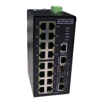
- Page 1 16 10/100TX + 2 10/100/1000T/ Mini-GBIC Combo Managed Industrial Switch User Manual SISTM1040-262D V1.00 Jul 2009...
-
Page 2: Fcc Warning
Transition Networks FCC Warning This Equipment has been tested and found to comply with the limits for a Class-A digital device, pursuant to Part 15 of the FCC rules. These limits are designed to provide reasonable protection against harmful interference in a residential installation. -
Page 3: Table Of Contents
Transition Networks Content Chapter 1 Overview ... 1 Introduction ... 1 The MINI-GBIC Advantage ... 1 High-Speed Transmissions ... 1 Dual Power Input ... 2 Flexible Mounting... 2 Advanced Protection... 2 Easy Troubleshooting ... 2 Features ... 3 Technical Specification ... 5 Package Contents... - Page 4 Chapter 4 Network Application ... 24 X-Ring Application... 25 Coupling Ring Application ... 26 Dual Homing Application... 27 Central Ring Application... 28 Chapter 5 Console Management ... 29 Connecting to the Console Port ... 29 Pin Assignment ... 29 Login in the Console Interface ... 30 CLI Management...
- Page 5 System Event Log ... 47 6.8.1 Syslog Configuration... 47 6.8.2 System Event Log—SMTP Configuration ... 49 6.8.3 System Event Log—Event Configuration ... 51 Fault Relay Alarm... 53 6.10 SNTP Configuration ... 54 6.11 IP Security... 58 6.12 User Authentication... 60 6.13 Port Statistics ...
- Page 6 6.21 QoS Configuration... 99 6.21.1 QoS Policy and Priority Type ... 99 6.21.2 Port-based Priority ... 101 6.21.3 COS Configuration... 101 6.21.4 TOS Configuration ... 101 6.22 IGMP Configuration... 103 6.23 X-Ring ... 105 6.24 Security—802.1X/Radius Configuration ... 108 6.25.1 System Configuration...
- Page 7 Transition Networks SISTM1040-262D-LRT Trunk Commands Set ... 130 VLAN Commands Set... 132 Spanning Tree Commands Set... 134 QOS Commands Set ... 136 IGMP Commands Set ... 137 Mac / Filter Table Commands Set... 138 SNMP Commands Set... 139 Port Mirroring Commands Set... 141 802.1x Commands Set ...
-
Page 8: Chapter 1 Overview
70km or 110km (single-mode)—and the slot supports SFP modules for WDM single-fiber transmissions. This means that you can easily change the transmission mode and distance of the switch by simply pulling out the SFP module and plugging in a different module. The SFP modules are hot-swappable and plug-and-play. -
Page 9: Dual Power Input
GBIC Combo Managed Industrial Switch is with power reserve protection to prevent the switch device broken by wrong power wiring. When one of power input is fail, P-Fail LED will turn on and send an alarm through a relay output for notifying user. -
Page 10: Features
1.2 Features System Interface/Performance RJ-45 ports support auto MDI/MDI-X function SFP (Mini-GBIC) supports 100/1000 Dual Mode Store-and-Forward switching architecture Back-plane (Switching Fabric): 7.2Gbps 1Mbits Packet Buffer 8K MAC Address Table Power Supply Wide-range Redundant Power Design Power Polarity Reverse Protect Overload Current Protection VLAN Port Based VLAN... - Page 11 IGMP with Query mode for Multi Media Application Case/Installation IP-30 Protection DIN Rail and Wall Mount Design Spanning Tree Support IEEE 802.1d Spanning Tree Support IEEE 802.1w Rapid Spanning Tree X-ring X-ring, Dual Homing, and Couple Ring Topology Provide redundant backup feature and recovery time below 20ms Bandwidth Control Ingress Packet Filter and Egress Rate Limit Broadcast/Multicast Packet Filter Control...
-
Page 12: Technical Specification
1.3 Technical Specification The technical specifications of 16 10/100/1000T + 2 10/100/1000T 100/1000 Mini-GBIC Managed Industrial Switch are listed as follows. Communications Compatibility Transmission Speed Interface Connectors LED Indicators Network Management Configuration VLAN Redundancy 24-Hour Technical Support: 1-800-260-1312 IEEE 802.3, 802.3u, 802.3ab IEEE 802.3x, 802.3z, 802.3ad... - Page 13 Security Traffic Control Diagnostics Power Power Consumption Power Input Fault Output Mechanism Dimensions (WxHxD) Enclosure Mounting Protection ESD (Ethernet) Surge (EFT for power) Power Reverse Overload current protection Environment Operating Temperature 24-Hour Technical Support: 1-800-260-1312 IP Access security, post security, DHCP Server, Per Port IP Binding, 802.1X Port Access Control IGMP Snooping/Query for multicast group management Port Trunking, Static/802.3ad LACP...
- Page 14 Operating Humidity Storage Temperature Storage Humidity Certifications Safety Free Fall Shock Vibration 24-Hour Technical Support: 1-800-260-1312 5% ~ 95% (non-condensing) -40 ~ 85 5% ~ 95% (non-condensing) UL, cUL, CE EN60950-1 Class1 / Division 2 FCC Class A CE EN61000-6-2 CE EN61000-6-4 CE EN61000-4-2 (ESD) CE EN61000-4-3 (RS)
-
Page 15: Package Contents
Pluggable Terminal Block x 1 Mounting plate x 2 RJ-45 to DB9-Female cable x 1 Compare the contents of the industrial switch with the standard checklist above. If any item is damaged or missing, please contact the local dealer for service. 1.5 Safety Precaution Attention IF DC voltage is supplied by an external circuit, please use a protection device on the power supply input. -
Page 16: Chapter 2 Hardware Description
Transition Networks Chapter 2 Hardware Description This section describes the Industrial switch’s hardware spec, port, cabling information, and wiring installation. 2.1 Physical Dimension 16 10/100TX + 2 10/100/1000T/Mini-GBIC Combo Managed Industrial Switch dimension (W x D x H) are 72mm x 105mm x 152mm 2.2 Front Panel... -
Page 17: Bottom View
2.3 Bottom View The bottom panel of the 16 10/100TX + 2 10/100/1000T/Mini-GBIC Combo w/ X-Ring L2 Managed Industrial Switch has one terminal block connector with two DC power inputs and one fault alarm output. Bottom Panel of the industrial switch... -
Page 18: Led Indicators
2.4 LED Indicators The diagnostic LEDs that provide real-time information of system and optional status are located on the front panel of the industrial switch. The following table provides the description of the LED status and their meanings for the switch. - Page 19 (Lower LED) Off Link/Active (P17, P18 Green SFP) Green P1 ~ P16 Amber 24-Hour Technical Support: 1-800-260-1312 10/100M The SFP port is linking The port is transmitting or receiving packets Blinks from the TX device. No device attached A network device is detected. The port is transmitting or receiving packets Blinking from the TX device.
-
Page 20: Chapter 3 Hardware Installation
3.1 Installation Steps 1. Unpack the Industrial switch 2. Check if the DIN-Rail is screwed on the Industrial switch or not. If the DIN-Rail is not screwed on the Industrial switch, please refer to DIN-Rail Mounting section for DIN- Rail installation. If users want to wall mount the Industrial switch, please refer to Wall Mount Plate Mounting section for wall mount plate installation. -
Page 21: Din-Rail Mounting
3.2 DIN-Rail Mounting The DIN-Rail is screwed on the industrial switch when out of factory. If the DIN-Rail is not screwed on the industrial switch, please see the following pictures to screw the DIN- Rail on the switch. Follow the steps below to hang the industrial switch. - Page 22 First, insert the top of DIN-Rail into the track. Then, lightly push the DIN-Rail into the track. Check if the DIN-Rail is tightened on the track or not. To remove the industrial switch from the track, reverse above steps. 24-Hour Technical Support: 1-800-260-1312 SISTM1040-262D-LRT...
-
Page 23: Wall Mount Plate Mounting
3.3 Wall Mount Plate Mounting Follow the steps below to mount the industrial switch with wall mount plate. 1. Remove the DIN-Rail from the industrial switch; loose the screws to remove the DIN- Rail. 2. Place the wall mount plate on the rear panel of the industrial switch. -
Page 24: Wiring The Power Inputs
Transition Networks 3.4 Wiring the Power Inputs Please follow the steps below to insert the power wires. 1. Insert DC power wires into the contacts 1 and 2 for power 1, or 5 and 6 for power. 2. Tighten the wire-clamp screws for preventing the wires from loosing. -
Page 25: Wiring The Fault Alarm Contact
The fault alarm contacts are in the middle of the terminal block connector as the picture shows below. Inserting the wires, the switch will detect the fault status of the power failure, or port link failure (available for managed model) and then forms an open circuit. -
Page 26: Cabling
3.6 Cabling Use four twisted-pair, Category 5e or above cabling for RJ-45 port connection. The cable between the switch and the link partner (switch, hub, workstation, etc.) must be less than 100 meters (328 ft.) long. Fiber segment using single-mode connector type must use 9/125 µm single-mode fiber cable. - Page 27 To connect the transceiver and LC cable, please follow the steps shown below: First, insert the transceiver into the SFP module. Notice that the triangle mark is the bottom of the module. Transceiver to the SFP module Transceiver Inserted Second, insert the fiber cable of LC connector into the transceiver. 24-Hour Technical Support: 1-800-260-1312 International: 00-1-952-941-7600...
- Page 28 LC connector to the transceiver 24-Hour Technical Support: 1-800-260-1312 International: 00-1-952-941-7600...
- Page 29 To remove the LC connector from the transceiver, please follow the steps shown below: First, press the upper side of the LC connector to release from the transceiver and pull it out. Remove LC connector Second, push down the metal loop and pull the transceiver out by the plastic handle. Pull out from the transceiver 24-Hour Technical Support: 1-800-260-1312 International: 00-1-952-941-7600...
- Page 30 24-Hour Technical Support: 1-800-260-1312 International: 00-1-952-941-7600...
-
Page 31: Chapter 4 Network Application
Transition Networks SISTM1040-262D-LRT Chapter 4 Network Application This chapter provides some sample applications to help users have more actual ideas of industrial switch applications. A sample application of the industrial switch is shown below: 24-Hour Technical Support: 1-800-260-1312 International: 00-1-952-941-7600... -
Page 32: X-Ring Application
SISTM1040-262D-LRT 4.1 X-Ring Application The industrial switch supports the X-Ring protocol that can help the network system to recovery from network connection failure within 20ms or less, making the network system more reliable. The X-Ring algorithm is similar to spanning tree protocol (STP) algorithm but its recovery time is faster than STP. -
Page 33: Coupling Ring Application
4—which are connected to each other via the paths in red. Please note that the Coupling Ring Backup Path between switch 1 and switch 3 is blocked; it will work only when the path between switch 2 and switch 4 is broken or disconnected. -
Page 34: Dual Homing Application
Dual Homing function is to prevent lost connection from an X-Ring group and upper level/core switch. Assign two ports to be the Dual Homing port that is backup port in the X-Ring group. The Dual Homing function only works when the X-Ring function is active. -
Page 35: Central Ring Application
Central ring is an advanced function which supports backup connection for transmission. If the connection fails, the system will recover from failure within 20 milliseconds. Apart from that, Central Ring also can handle up to 4 rings by configuring a single switch only as the Ring Master switch. -
Page 36: Chapter 5 Console Management
The supplied cable includes on one end an RS-232 connector and the other end an RJ- 45 connector. Attach the end of RS-232 connector to PC or terminal and the other end of RJ-45 connector to the console port of the switch. The connected terminal or PC must support the terminal emulation program. -
Page 37: Login In The Console Interface
Brown 5.3 Login in the Console Interface When the connection between Switch and PC is ready, turn on the PC and run a terminal emulation program or Hyper Terminal and configure its communication parameters to match the following default characteristics of the console port:... - Page 38 Enter key to have the login prompt appears. Key in ‘root’ (default value) for both User name and Password (use Enter key to switch), then press Enter and the Main Menu of console management appears. Please see below figure for login screen.
-
Page 39: Cli Management
Transition Networks 5.4 CLI Management The system supports the console management—CLI command. After you log in on to the system, you will see a command prompt. To enter CLI management interface, type in “enable” command. The following table lists the CLI commands and description. - Page 40 • Save configuration Use this mode to configure those parameters that are going to be applied to your switch. Use this mode to configure VLAN- specific parameters. Use this mode to configure parameters for the switch and Ethernet ports.
-
Page 41: Chapter 6 Web-Based Management
Before using the web management, install the industrial switch on the network and make sure that any one of the PCs on the network can connect with the industrial switch through the web browser. The industrial switch default value of IP, subnet mask, username and password are listed as below: IP Address: 192.168.1.77... -
Page 42: System Login
6.3 System Login Launch the Internet Explorer on the PC Key in “http:// “+” the IP address of the switch”, and then Press “Enter”. The login screen will appear right after Key in the user name and password. The default user name and password are the same as ‘root’. -
Page 43: System Information
6.4 System Information User can assign the system name, description, location and contact personnel to identify the switch. The version table below is a read-only field to show the basic information of the switch. System Name: Assign the system name of the switch (The maximum length is 64 bytes) System Description: Describes the switch. -
Page 44: Ip Configuration
DHCP client. The network DHCP server will assign the IP address to the switch and display it in this column. The default IP is 192.168.1.77 or the user has to assign an IP address manually when DHCP Client is disabled. - Page 45 IP configuration interface 24-Hour Technical Support: 1-800-260-1312 International: 00-1-952-941-7600...
-
Page 46: Dhcp Server
IP address. The system provides the DHCP server function. Having enabled the DHCP server function, the switch system will be configured as a DHCP server. 24-Hour Technical Support: 1-800-260-1312 International: 00-1-952-941-7600... -
Page 47: System Configuration
SISTM1040-262D-LRT 6.6.1 System configuration DHCP Server: Enable or Disable the DHCP Server function. Enable—the switch will be the DHCP server on your local network. Low IP Address: Type in an IP address. Low IP address is the beginning of the dynamic IP range. - Page 48 DHCP Server Configuration interface 24-Hour Technical Support: 1-800-260-1312 International: 00-1-952-941-7600...
-
Page 49: Client Entries
Transition Networks SISTM1040-262D-LRT 6.6.2 Client Entries When the DHCP server function is enabled, the system will collect the DHCP client information including the assigned IP address, the MAC address of the client device, the IP assigning type, status and lease time. -
Page 50: Port And Ip Bindings
Transition Networks SISTM1040-262D-LRT 6.6.3 Port and IP Bindings Assign the dynamic IP address bound with the port to the connected client. The user is allowed to fill each port column with one particular IP address. When the device is connecting to the port and asks for IP assigning, the system will assign the IP address bound with the port. -
Page 51: Tftp
Transition Networks 6.7 TFTP It provides the functions allowing the user to update the switch firmware via the Trivial File Transfer Protocol (TFTP) server. Before updating, make sure the TFTP server is ready and the firmware image is located on the TFTP server. -
Page 52: Restore Configuration
You can restore a previous backup configuration from the TFTP server to recover the settings. Before doing that, you must locate the image file on the TFTP server first and the switch will download back the flash image. TFTP Server IP Address: Type in the TFTP server IP. -
Page 53: Backup Configuration
Transition Networks 6.7.3 Backup Configuration You can back up the current configuration from flash ROM to the TFTP server for the purpose of recovering the configuration later. It helps you to avoid wasting time on configuring the settings by backing up the configuration. -
Page 54: System Event Log
Both. ‘Client Only’ means the system event log will only be sent to this interface of the switch, but on the other hand ‘Server Only’ means the system log will only be sent to the remote system log server with its IP assigned. If the mode is set in ‘Both’, the system event log will be sent to the remote server and this interface. - Page 55 Syslog Configuration interface 24-Hour Technical Support: 1-800-260-1312 International: 00-1-952-941-7600...
-
Page 56: System Event Log-Smtp Configuration
SMTP Server IP: Assign the mail server IP address (when Email Alert is enabled, this function will then be available). Sender: Type in an alias of the switch in complete email address format, e.g. switch101@123.com, to identify where the e-mail alert comes from. - Page 57 SMTP Configuration interface 24-Hour Technical Support: 1-800-260-1312 International: 00-1-952-941-7600...
-
Page 58: System Event Log-Event Configuration
Transition Networks 6.8.3 System Event Log—Event Configuration Having checked the Syslog/SMTP checkboxes, the event log/email alert will be sent to the system log server and the SMTP server respectively. Also, Port event log/alert (link up, link down, and both) can be sent to the system log server/SMTP server respectively by setting the trigger condition. - Page 59 Event Configuration interface 24-Hour Technical Support: 1-800-260-1312 International: 00-1-952-941-7600...
-
Page 60: Fault Relay Alarm
Transition Networks 6.9 Fault Relay Alarm The Fault Relay Alarm function provides the Power Failure and Port Link Down/Broken detection. With both power input 1 and power input 2 installed and the check boxes of power 1/power 2 checked, the FAULT LED indicator will then light up when any one of the power failures occurs. -
Page 61: Sntp Configuration
SNTP Client: Enable/disable SNTP function to get the time from the SNTP server. Daylight Saving Time: This is used as a control switch to enable/disable daylight saving period and daylight saving offset. Users can configure Daylight Saving Period and Daylight Saving Offset in a certain period time and offset time while there is no need to enable daylight saving function. - Page 62 EDT - Eastern Daylight EST - Eastern Standard CDT - Central Daylight CST - Central Standard MDT - Mountain Daylight MST - Mountain Standard PDT - Pacific Daylight PST - Pacific Standard ADT - Alaskan Daylight ALA - Alaskan Standard HAW - Hawaiian Standard Nome, Alaska...
- Page 63 SNTP Sever URL: Set the SNTP server IP address. You can assign a local network time server IP address or an internet time server IP address. Switch Timer: When the switch has successfully connected to the SNTP server whose IP address was assigned in the column field of SNTP Server URL, the current coordinated time is displayed here.
- Page 64 minute between 0 and 720, which means you can set the offset up to 12 hours. Click to have the configuration take effect. Apply SNTP Configuration interface 24-Hour Technical Support: 1-800-260-1312 International: 00-1-952-941-7600...
-
Page 65: Ip Security
IP security function allows the user to assign 10 specific IP addresses that have permission to manage the switch through the http and telnet services for the securing switch management. The purpose of giving the limited IP addresses permission is to allow only the authorized personnel/device can do the management task on the switch. - Page 66 IP Security interface 24-Hour Technical Support: 1-800-260-1312 International: 00-1-952-941-7600...
-
Page 67: User Authentication
Transition Networks 6.12 User Authentication Change web management login user name and password for management security. User name: Type in the new user name (The default is ‘root’) Password: Type in the new password (The default is ‘root’) Confirm password: Re-type the new password... -
Page 68: Port Statistics
Transition Networks 6.13 Port Statistics The following chart provides the current statistic information which displays the real-time packet transfer status for each port. The user might use the information to plan and implement the network, or check and find the problem when collisions or heavy traffic occurs. - Page 69 Port Statistics interface 24-Hour Technical Support: 1-800-260-1312 International: 00-1-952-941-7600...
-
Page 70: Port Control
Transition Networks 6.14 Port Control In Port control you can configure the settings of each port to control the connection parameters, and the status of each port is listed beneath. Port: Use the scroll bar and click on the port number to choose the port to be configured. - Page 71 Port Control interface 24-Hour Technical Support: 1-800-260-1312 International: 00-1-952-941-7600...
-
Page 72: Port Trunk
6.15.1 Aggregator setting System Priority: A value which is used to identify the active LACP. The switch with the lowest value has the highest priority and is selected as the active LACP peer of the trunk group. - Page 73 Select the ports to join the trunk group. The system allows a maximum of four ports to be aggregated in a trunk group. Click and the ports focused in the right side will be shifted to the left side. To remove unwanted ports, select the ports and click Remove When LACP enabled, you can configure LACP Active/Passive status for each...
-
Page 74: Aggregator Information
Transition Networks SISTM1040-262D-LRT 6.15.2 Aggregator Information LACP disabled Having set up the aggregator setting with LACP disabled, you will see the local static trunk group information on the tab of Aggregator Information. Assigning 2 ports to a trunk group with LACP disabled... - Page 75 Group Key: This is a read-only column field that displays the trunk group ID. Port Member: This is a read-only column field that displays the members of this static trunk group. 24-Hour Technical Support: 1-800-260-1312 International: 00-1-952-941-7600...
- Page 76 Transition Networks LACP enabled Having set up the aggregator setting with LACP enabled, you will see the trunking group information between two switches on the tab of Aggregator Information. Switch 1 configuration Set System Priority of the trunk group. The default is 1.
- Page 77 Aggregation Information of Switch 1 Click on the tab of Aggregator Information to check the trunked group information as the illustration shown above after the two switches configured. 24-Hour Technical Support: 1-800-260-1312 International: 00-1-952-941-7600...
- Page 78 Transition Networks Switch 2 configuration Set System Priority of the trunk group. The default is 1. Select a trunk group ID by pull down the drop-down menu bar. Enable LACP. Include the member ports by clicking the Add button after selecting the port number and the column field of Work Ports changes automatically.
- Page 79 Aggregation Information of Switch 2 Click on the tab of Aggregator Information to check the trunked group information as the illustration shown above after the two switches configured. 24-Hour Technical Support: 1-800-260-1312 International: 00-1-952-941-7600...
-
Page 80: State Activity
Transition Networks 6.15.3 State Activity Having set up the LACP aggregator on the tab of Aggregator Setting, you can configure the state activity for the members of the LACP trunk group. You can tick or cancel the checkbox beside the state label. When you remove the tick mark of the port and click , the port state activity will change to Passive. - Page 81 State Activity of Switch 2 24-Hour Technical Support: 1-800-260-1312 International: 00-1-952-941-7600...
-
Page 82: Port Mirroring
Transition Networks 6.16 Port Mirroring The Port mirroring is a method for monitor traffic in switched networks. Traffic through ports can be monitored by one specific port, which means traffic goes in or out monitored (source) ports will be duplicated into mirror (destination) port. - Page 83 Port Trunk – Port Mirroring interface 24-Hour Technical Support: 1-800-260-1312 International: 00-1-952-941-7600...
-
Page 84: Rate Limiting
All the ports support port ingress and egress rate control. For example, assume port 1 is 10Mbps, users can set it’s effective egress rate is 1Mbps, ingress rate is 500Kbps. The switch performs the ingress rate by packet counter to meet the specified rate Ingress: Enter the port effective ingress rate (The default value is “0”). - Page 85 Rate Limiting interface 24-Hour Technical Support: 1-800-260-1312 International: 00-1-952-941-7600...
-
Page 86: Vlan Configuration
VLAN will receive traffic from the ones of the same VLAN. Basically, creating a VLAN on a switch is logically equivalent of reconnecting a group of network devices to another Layer 2 switch. However, all the network devices are still plugged into the same switch physically. -
Page 87: Port-Based Vlan
Transition Networks 6.18.1 Port-based VLAN A port-based VLAN basically consists of its members—ports, which means the VLAN is created by grouping the selected ports. This method provides the convenience for users to configure a simple VLAN easily without complicated steps. Packets can go among only members of the same VLAN group. - Page 88 Click to add a new VLAN group (The maximum VLAN groups are up to 64). VLAN—Port Based Add interface Enter the group name and VLAN ID. Add the selected port number into the right field to group these members to be a VLAN group, or remove any of them listed in the right field from the VLAN.
- Page 89 Edit to modify group name, VLAN ID, or add/remove the members of the existing VLAN group. [NOTE] Remember to execute the “Save Configuration” action, otherwise the new configuration will lose when switch power off. 24-Hour Technical Support: 1-800-260-1312 International: 00-1-952-941-7600...
-
Page 90: Q Vlan
Virtual Local Area Network (VLAN) can be implemented on the switch to logically create different broadcast domain. When the 802.1Q VLAN function is enabled, all ports on the switch belong to default VLAN of VID 1, which means they logically are regarded as members of the same broadcast domain. - Page 91 Management VLAN ID: Only when the VLAN members, whose Untagged VID (PVID) equals to the value in this column, will have the permission to access the switch. The default value is ‘0’ that means this limit is not enabled (all members in different VLANs can access this switch).
- Page 92 2. It’s not necessary to type ‘1’ in the tagged VID. The trunk port will forward the frames of VLAN 1. 3. The trunk port has to be connected to a trunk/hybrid port of the other switch. Both the tagged VID of the two ports have to be the same.
- Page 93 Group Configuration Edit the existing VLAN Group. Select the VLAN group in the table list. Click Edit 24-Hour Technical Support: 1-800-260-1312 802.1Q VLAN interface International: 00-1-952-941-7600...
- Page 94 Group Configuration interface You can modify the VLAN group name and VLAN ID. 24-Hour Technical Support: 1-800-260-1312 International: 00-1-952-941-7600...
- Page 95 Group Configuration interface Click Apply 24-Hour Technical Support: 1-800-260-1312 International: 00-1-952-941-7600...
-
Page 96: Rapid Spanning Tree
Priority (0-61440): The switch with the lowest value has the highest priority and is selected as the root. If the value is changed, the user must reboot the switch. The value must be a multiple of 4096 according to the protocol standard rule. - Page 97 RSTP System Configuration interface 24-Hour Technical Support: 1-800-260-1312 International: 00-1-952-941-7600...
-
Page 98: Port Configuration
Transition Networks 6.19.2 Port Configuration This web page provides the port configuration interface for RSTP. You can assign higher or lower priority to each port. Rapid spanning tree will have the port with the higher priority in forwarding state and block other ports to make certain that there is no loop in the LAN. - Page 99 RSTP Port Configuration interface 24-Hour Technical Support: 1-800-260-1312 International: 00-1-952-941-7600...
-
Page 100: Snmp Configuration
To remove the community string, select the community string that you defined before and click strings. You can remove them but after resetting the switch to default, the two strings show up again. Agent Mode: Select the SNMP version that you want to use it. And then click Change to switch to the selected SNMP version mode. - Page 101 SNMP System Configuration interface 24-Hour Technical Support: 1-800-260-1312 International: 00-1-952-941-7600...
-
Page 102: Trap Configuration
A trap manager is a management station that receives the trap messages generated by the switch. If no trap manager is defined, no traps will be issued. To define a management station as a trap manager, assign an IP address, enter the SNMP community strings, and select the SNMP trap version. -
Page 103: Snmpv3 Configuration
Transition Networks 6.20.3 SNMPV3 Configuration Configure the SNMP V3 function. Context Table Configure SNMP v3 context table. Assign the context name of context table. Click to add context name. Click User Table Configure SNMP v3 user table.. User ID: set up the user name. - Page 104 SNMP V3 configuration interface 24-Hour Technical Support: 1-800-260-1312 International: 00-1-952-941-7600...
- Page 105 Access Table Configure SNMP v3 access table. Context Prefix: set up the context name. Group Name: set up the group. Security Level: select the access level. Context Match Rule: select the context match rule. Read View Name: set up the read view. Write View Name: set up the write view.
-
Page 106: Qos Configuration
QoS policy. Qos Policy: Select the QoS policy rule. Using the 8,4,2,1 weight fair queue scheme: The switch will follow 8:4:2:1 rate to process priority queue from High to lowest queue. For example, while... - Page 107 QoS Configuration interface 24-Hour Technical Support: 1-800-260-1312 International: 00-1-952-941-7600...
-
Page 108: Port-Based Priority
6.21.2 Port-based Priority Configure the priority level for each port. With the drop-down selection item of Priority Type above being selected as Port-based, this control item will then be available to set the queuing policy for each port. Port x: Each port has 4 priority levels—High, Middle, Low, and Lowest—to be chosen. - Page 109 of priority—High, Middle, Low, and Lowest. The default value is ‘Lowest’ priority for each level. When the IP packet is received, the system will check the TOS level value in the IP packet that has received. For example, the user sets the TOS level 25 as high, the system will check the TOS value of the received IP packet.
-
Page 110: Igmp Configuration
Group The switch support IP multicast, you can enable IGMP protocol on web management’s switch setting advanced page, then the IGMP snooping information displays. IP multicast addresses range are from 224.0.0.0 through 239.255.255.255. - Page 111 IGMP Configuration interface 24-Hour Technical Support: 1-800-260-1312 International: 00-1-952-941-7600...
-
Page 112: X-Ring
Ring topology, every switch should be enabled with X-Ring function and two ports should be assigned as the member ports in the ring. Only one switch in the X-Ring group would be set as the master switch that one of its two member ports would be blocked, called backup port, and another port is called working port. - Page 113 X-rings. Enable Dual Homing: Set up one of the ports on the switch to be the Dual Homing port. For a switch, there is only one Dual Homing port. Dual Homing function works only when the X-Ring function enabled.
- Page 114 [NOTE] 1. When the X-Ring function enabled, the user must disable the RSTP. The X-Ring function and RSTP function cannot exist on a switch at the same time. 2. Remember to execute the “Save Configuration” action, otherwise the new configuration will lose when switch powers off.
-
Page 115: Security-802.1X/Radius Configuration
Security—802.1X/Radius Configuration 802.1x is an IEEE authentication specification which prevents the client from accessing a wireless access point or wired switch until it provides authority, like the user name and password that are verified by an authentication server (such as RADIUS server). - Page 116 802.1x System Configuration interface 24-Hour Technical Support: 1-800-260-1312 International: 00-1-952-941-7600...
-
Page 117: Port Configuration
Transition Networks 6.25.2 Port Configuration You can configure the 802.1x authentication state for each port. The state provides Disable, Accept, Reject, and Authorize. Reject: The specified port is required to be held in the unauthorized state. Accept: The specified port is required to be held in the authorized state. - Page 118 802.1x Per Port Setting interface 24-Hour Technical Support: 1-800-260-1312 International: 00-1-952-941-7600...
-
Page 119: Misc Configuration
Supplicant Timeout: Set the period of time the switch waits for a supplicant response to an EAP request. Server Timeout: Set the period of time the switch waits for a server response to an authentication request. Max Requests: Set the number of authentication that must time-out before authentication fails and the authentication session ends. -
Page 120: Mac Address Table
Use the MAC address table to ensure the port security. 6.26.1 Static MAC Address You can add a static MAC address that remains in the switch's address table regardless of whether the device is physically connected to the switch. This saves the switch from having to re-learn a device's MAC address when the disconnected or powered-off device is active on the network again. - Page 121 Static MAC Addresses interface 24-Hour Technical Support: 1-800-260-1312 International: 00-1-952-941-7600...
-
Page 122: Mac Filtering
Transition Networks 6.26.2 MAC Filtering By filtering MAC address, the switch can easily filter the pre-configured MAC address and reduce the un-safety. You can add and delete filtering MAC address. MAC Address: Enter the MAC address that you want to filter. -
Page 123: All Mac Addresses
Transition Networks 6.26.3 All MAC Addresses You can view all of the MAC addresses learned by the selected port. Select the port number. The selected port of static & dynamic MAC address information will be displayed in here. Click Clear MAC Table current port shown on the screen. -
Page 124: Factory Default
Transition Networks SISTM1040-262D-LRT 6.26 Factory Default Reset switch to default configuration. Click Default to reset all configurations to the default value. Factory Default interface 24-Hour Technical Support: 1-800-260-1312 International: 00-1-952-941-7600... -
Page 125: Save Configuration
Transition Networks SISTM1040-262D-LRT 6.27 Save Configuration Save all configurations that you have made in the system. To ensure the all Save Flash configuration will be saved. Click to save the all configuration to the flash memory. Save Configuration interface 24-Hour Technical Support: 1-800-260-1312... -
Page 126: System Reboot
Transition Networks SISTM1040-262D-LRT 6.28 System Reboot Reboot the switch in software reset. Click Reboot to reboot the system. System Reboot interface 24-Hour Technical Support: 1-800-260-1312 International: 00-1-952-941-7600... -
Page 127: Troubles Shooting
SISTM1040-262D-LRT Troubleshooting Verify the switch is using the right power cord/adapter (DC 24-48V), please don’t use a power adapter with DC output higher than 48V, or it may damage this device. Select the proper UTP/STP cable to construct the user network. Use unshielded... -
Page 128: Appendix A-Rj-45 Pin Assignment
The UTP/STP ports will automatically sense for Fast Ethernet (10Base-T/100Base-TX connections), or Gigabit Ethernet (10Base-T/100Base-TX/1000Base-T connections). Auto MDI/MDIX means that the switch can connect to another switch or workstation without changing straight through or crossover cabling. See the figures below for straight through and crossover cable schematic. - Page 129 Transmit Data minus (TD-) 10/100Base-TX Cable Schematic The following two figures show the 10/100Base-TX cable schematic. 10/100/1000Base-TX Pin outs The following figure shows the 10/100/1000 Ethernet RJ-45 pin outs. 24-Hour Technical Support: 1-800-260-1312 Receive Data minus (RD-) Straight-through cable schematic Cross over cable schematic International: 00-1-952-941-7600...
- Page 130 10/100/1000Base-TX Cable Schematic Straight through cables schematic 24-Hour Technical Support: 1-800-260-1312 International: 00-1-952-941-7600...
- Page 131 Cross over cables schematic 24-Hour Technical Support: 1-800-260-1312 International: 00-1-952-941-7600...
-
Page 132: Appendix B-Command Sets
Transition Networks Appendix B—Command Sets Commands Set List User EXEC Privileged EXEC Global configuration VLAN database Interface configuration System Commands Set Commands Level Description show config show terminal write memory system name [System Name] system location [System Location] system description... - Page 133 Configure subnet mask for DHCP clients Configure gateway for DHCP clients Configure DNS IP for DHCP clients Configure lease time (in hour) Set static IP for DHCP switch(config)#interface International: 00-1-952-941-7600 192.168.1.254 switch(config)#ip dhcp switch#show ip switch(config)#no ip dhcp switch(config)#reload switch(config)#default...
- Page 134 Enable IP security function Enable IP security of HTTP server Enable IP security of telnet server Set the IP security list switch(config)#security ip 1 Show the information of IP security Disable IP security function Disable IP security of HTTP server...
-
Page 135: Port Commands Set
Disable security of interface Set interface ingress limit frame type to “accept all frame” International: 00-1-952-941-7600 Example switch(config)#interface fastEthernet 2 switch(config)#interface fastEthernet 2 switch(config-if)#duplex full switch(config)#interface fastEthernet 2 switch(config-if)#speed 100 switch(config-if)#no flowcontrol switch(config)#interface fastEthernet 2 switch(config-if)#security enable switch(config)#interface fastEthernet 2 switch(config-if)#no security... - Page 136 Show interfaces bandwidth control International: 00-1-952-941-7600 switch(config)#interface fastEthernet 2 switch(config-if)#bandwidth type broadcast-multicast-flooded- unicast switch(config)#interface fastEthernet 2 switch(config-if)#bandwidth type broadcast-multicast switch(config)#interface fastEthernet 2 switch(config-if)#bandwidth type broadcast-only switch(config)#interface fastEthernet 2 switch(config-if)#bandwidth in 100 switch(config)#interface fastEthernet 2 switch(config-if)#bandwidth out switch(config)#interface fastEthernet 2 switch(config-if)#show bandwidth...
-
Page 137: Trunk Commands Set
Clear interface accounting information Level Description Set port group system priority Set activity port International: 00-1-952-941-7600 switch(config)#interface fastEthernet 2 switch(config-if)#state Disable switch(config)#interface fastEthernet 2 switch(config-if)#show interface configuration switch(config)#interface fastEthernet 2 switch(config-if)#show interface status switch(config)#interface fastEthernet 2... - Page 138 International: 00-1-952-941-7600 switch(config)#aggregator group 1 1-4 lacp workp 2 switch(config)#aggregator group 2 1,4,3 lacp workp 3 switch(config)#aggregator group 1 2-4 nolacp switch(config)#aggregator group 1 3,1,2 nolacp switch#show aggregator 1 switch#show aggregator 2 switch#show aggregator 3 switch(config)#no aggreator lacp...
-
Page 139: Vlan Commands Set
[GroupID] show vlan no vlan group [GroupID] vlan 8021q name [GroupName] [VID] 24-Hour Technical Support: 1-800-260-1312 Remove a trunk group switch(config)#no aggreator Level Description Enter VLAN configure mode To set switch VLAN mode. No VLAN Add new port based VALN... - Page 140 Assign a hybrid link for VLAN by trunk group Show VLAN information Delete port base group ID International: 00-1-952-941-7600 switch(vlan)#vlan 8021q port 3 access-link untag 33 switch(vlan)#vlan 8021q port 3 trunk-link tag 2,3,6,99 switch(vlan)#vlan 8021q port 3 trunk-link tag 3-20 switch(vlan)#vlan 8021q port 3...
-
Page 141: Spanning Tree Commands Set
Use the spanning-tree max-age global configuration command to change the interval between messages the spanning tree receives from the root switch. If a switch does not receive a bridge protocol data unit (BPDU) message from the root switch within this interval, it... - Page 142 Spanning Tree Protocol (STP) calculations. In the event of a loop, spanning tree considers the path cost when selecting an interface to place International: 00-1-952-941-7600 switch(config)#spanning-tree forward-time 20 switch(config)#interface fastEthernet 2 switch(config-if)#stp-path-cost 20...
-
Page 143: Qos Commands Set
Admin Edge of STP priority on this interface. Admin NonSTP of STP priority on this interface. Displays a summary of the spanning-tree states. Disable spanning-tree. switch(config)#no spanning-tree Level Description Select QOS policy International: 00-1-952-941-7600 switch(config)#interface fastEthernet 2 switch(config-if)#stp-path-priority switch(config)#interface fastEthernet 2... -
Page 144: Igmp Commands Set
24-Hour Technical Support: 1-800-260-1312 scheduling Setting of QOS priority type Configure Port-based Priority Configure COS Priority Configure TOS Priority switch(config)#qos priority tos 3 Displays the information of QoS configuration Disable QoS function switch(config)#no qos Level Description Enable IGMP snooping function... -
Page 145: Mac / Filter Table Commands Set
MAC address table of interface (static) Remove an entry of MAC address table (filter) Remove dynamic entry of MAC address table International: 00-1-952-941-7600 switch#no igmp-query Example switch(config)#interface fastEthernet 2 switch(config-if)#mac-address- table static hwaddr 000012345678 switch(config)#mac-address-table filter hwaddr 000012348678 switch#show mac-address-table... -
Page 146: Snmp Commands Set
Configure the context name Configure the userprofile for SNMPV3 agent. Privacy password could be empty. International: 00-1-952-941-7600 Example switch(config)#snmp system- name l2switch switch(config)#snmp system- location lab switch(config)#snmp system- contact where switch(config)#snmp agent-mode v1v2cv3 switch(config)#snmp community- strings public right rw switch(config)#snmp-server host 192.168.1.50 community public... - Page 147 Exact views V1 V1 V1 switch(config)#snmpv3 mibview view V1 type Excluded sub-oid 1.3.6.1 switch#show snmp switch(config)#no snmp community-strings public switch(config)#no snmp-server host 192.168.1.50 switch(config)#no snmpv3 user Test switch(config)#no snmpv3 access context-name Test group G1 security-level AuthPr iv match-rule Exact views V1 V1...
-
Page 148: Port Mirroring Commands Set
Set TX destination port of monitor function Show port monitor information International: 00-1-952-941-7600 switch(config)#no snmpv3 mibview view V1 type Excluded sub-oid 1.3.6.1 Example switch(config)#interface fastEthernet 2 switch(config-if)#monitor RX switch(config)#monitor rx 2 switch(config)#monitor tx 3 switch#show monitor... -
Page 149: Commands Set
International: 00-1-952-941-7600 switch(config)#interface fastEthernet 2 switch(config-if)#show monitor switch(config)#interface fastEthernet 2 switch(config-if)#no monitor Example switch(config)# 8021x enable switch(config)# 8021x system radiusip 192.168.1.1 switch(config)# 8021x system serverport 1812 switch(config)# 8021x system accountport 1813 switch(config)# 8021x system sharedkey 123456... - Page 150 NAS ID Use the 802.1x misc quiet period global configuration command to specify the quiet period value of the switch. Use the 802.1x misc TX period global configuration command to set the TX period. Use the 802.1x misc...
-
Page 151: Tftp Commands Set
Get configuration from TFTP server and need to specify the IP of TFTP server and the file name of image. International: 00-1-952-941-7600 switch(config)# 8021x misc reauthperiod 3000 switch(config)#interface fastethernet 3 switch(config-if)#8021x portstate accept switch>show 8021x switch(config)#no 8021x... -
Page 152: Systemlog, Smtp And Event Commands Set
Set System log server IP address. Specified the log mode Displays system log. Show system log client & server information Disable systemlog functon Enable SMTP function switch(config)#smtp enable Configure SMTP server IP Enable SMTP authentication Configure authentication account Configure authentication password... - Page 153 Set X-ring topology changed event type Set port event for system log Set port event for SMTP Show event selection switch#show event Disable cold start event type Disable Authentication failure event type Disable X-ring topology changed event type...
-
Page 154: Sntp Commands Set
[IP] 24-Hour Technical Support: 1-800-260-1312 SMTP Show system log client & server information Level Description Enable SNTP function switch(config)#sntp enable Enable daylight saving time, if SNTP function is inactive, this command can’t be applied. Set period of daylight saving time, if SNTP function is inactive, this command can’t be... -
Page 155: X-Ring Commands Set
Enable ring master Enable couple ring Enable dual homing Configure 1st/2nd Ring Port Configure Coupling Port Configure Control Port switch(config)#ring controlport 2 Configure Dual Homing Port Show the information switch#show ring International: 00-1-952-941-7600 switch(config)#sntp timezone 22 switch#show sntp switch#show sntp timezone... - Page 156 24-Hour Technical Support: 1-800-260-1312 of X-Ring Disable X-ring Disable ring master Disable couple ring Disable dual homing International: 00-1-952-941-7600 switch(config)#no ring switch(config)# no ring master switch(config)# no ring couplering switch(config)# no ring dualhoming...
Need help?
Do you have a question about the SISTM1040-262D-LRT and is the answer not in the manual?
Questions and answers