Transition Networks SISPM1040-582-LRT Install Manual
Managed hardened poe++ switch
Hide thumbs
Also See for SISPM1040-582-LRT:
- Web user manual (506 pages) ,
- Cli reference manual (172 pages) ,
- Quick start manual (2 pages)
Table of Contents
Advertisement
Quick Links
Download this manual
See also:
Cli Reference Manual
Advertisement
Table of Contents
Troubleshooting

Related Manuals for Transition Networks SISPM1040-582-LRT


Summary of Contents for Transition Networks SISPM1040-582-LRT
- Page 1 Transition Networks SISPM1040‐582‐LRT Install Guide SISPM1040‐582‐LRT Managed Hardened PoE++ Switch (8) 10/100/1000Base‐T PoE++ Ports + (2) 100/1000Base‐X SFP Slot Install Guide 33755 Rev. B 33755 Rev. B https://www.transition.com Page 1 of 46 ...
- Page 2 Transition Networks SISPM1040‐582‐LRT Install Guide Trademarks All trademarks and registered trademarks are the property of their respective owners. Copyright Notice/Restrictions Copyright © 2018 Transition Networks. All rights reserved. No part of this work may be reproduced or used in any form or by any means (graphic, electronic or mechanical) without written permission from Transition Networks. Printed in the U.S.A. Contact Information Transition Networks 10900 Red Circle Drive Minnetonka, MN 55343 USA tel: +1.952.941.7600 | toll free: 1.800.526.9267 | fax: 952.941.2322 sales@transition.com | techsupport@transition.com | customerservice@transition.com SISPM1040‐582‐LRT Managed Hardened PoE++ Switch Install Guide, 33755 Rev. B Revision History Rev Date Description A 9/20/18 Initial release for FW v7.10.1492. B 10/17/18 Add safety warning. ...
-
Page 3: Table Of Contents
Transition Networks SISPM1040‐582‐LRT Install Guide Table of Contents 1. Introduction .............................. 5 Key Features ................................ 5 Benefits .................................. 5 Specifications ................................ 6 Software Features .............................. 8 Manual Overview ..............................11 Related Manuals ..............................11 2. Product Description ............................ 1 2 Overview ................................12 Back Panel ................................12 Front Panel ................................13 LED Indicators ................................14 ... - Page 4 Transition Networks SISPM1040‐582‐LRT Install Guide Mode A vs. Mode B ............................35 802.3af/at Standard “compliant” vs "compatible" PDs ..................35 Typical PD Power Requirements ........................35 Calculate PoE Power Budget ..........................35 VoIP vs SIP ................................35 Mixing POE and Non‐POE Devices ........................35 Ethernet and PoE Intra‐Building Cabling Warnings ...................36 Legacy PD Detection / Capacitor Detection .......................36 PoE ++ Connectivity, Arcing, and Temperature Issues ..................36 PoE/PoE+/PoE++ Comparison Chart ........................37 Notes from Draft Standard for Ethernet Amendment 2: PoE over 4 Pairs (IEEE 802.3bt) ........37 Term Definitions ..............................38 General Safety ..............................38 Network Safety ..............................39 Patch Panel Considerations ..........................39 Electromagnetic Emissions ..........................39 ...
-
Page 5: Introduction
Transition Networks SISPM1040‐582‐LRT Install Guide 1. Introduction The SISPM1040‐582‐LRT industrial L2+ managed GbE PoE++ switch is the next generation industrial grade Ethernet switch offering powerful L2 and basic L3 features for better functionality and usability. Along with its extensive management features, the SISPM1040‐582‐LRT also provides Carrier Ethernet features such as OAM, CFM, ERPS, EPS, and PTPv2, making it suitable for industrial and Carrier Ethernet applications. The SISPM1040‐582‐LRT delivers 8 (10M/100M/1G) RJ45 with PoE++ (802.3 at/af/bt for up to 480W total) ports, 2 GbE SFP ports and an RJ45 Console port. The SISPM1040‐582‐LRT provides high hardware performance and operating environment flexibility for Industrial and Carrier Ethernet applications. The embedded Device Managed System (DMS) feature makes it easy to use, configure, install, and troubleshoot in video surveillance, wireless access, and other industrial applications. The SISPM1040‐582‐LRT delivers ideal management simplicity, user experience, and low total cost of ownership (TCO). Key Features • Rapid Ring / Ring To Ring / Rapid Chain • DMS (Device Management System) built in • ITU‐T G.8031 Ethernet Linear Protection Switching (EPS) • ITU‐T G.8032 Ethernet Ring Protection Switching (ERPS) • IEEE 1588v2 PTP IEEE 802.3ah OAM ... -
Page 6: Specifications
Transition Networks SISPM1040‐582‐LRT Install Guide Easy to Install, Configure and Troubleshoot with DMS: the embedded Device Management System (DMS) provides embedded functions to facilitate devices management at anytime and anywhere. Its user‐friendly interface helps manage devices intuitively. It supports various IP device types (e.g. PC, IP‐phones, PTZ cameras, WiFi‐AP) to enhance manageability and save time and cost during installation and maintenance. Lower TCO with Energy‐efficient design: The switch is designed to help companies save power and reduce TCO by Energy Efficient Ethernet (IEEE 802.3az). It can help build a green Ethernet network environment. Ordering Information SKU Description Hardened PoE++ Switch. (8) 10/100/1000Base‐T PoE++ and (2) 100/1000Base‐X SFP SISPM1040‐582‐LRT slots; 52V ‐ 57 VDC. Optional Accessories (sold separately) Hardened SFPs See Transition Networks webpage for Hardened SFPs. Industrial Power Supply. Input 90‐264 VAC, 127‐370 VDC. Output: 48 ~ 55 VDC, 10A, 25160 480 Watts Industrial Power Supply. Input: 85‐264 VAC, 124‐370 VDC. Output: 48 ~ 55 VDC, 5A, 25104 240 Watts. WMBH‐01 Wall Mount Bracket. ... - Page 7 Transition Networks SISPM1040‐582‐LRT Install Guide Dimensions, Weight, Mounting Dimensions (WxHxD) Weight Mounting Type Millimeters Inches Kilograms Pounds 62 x 135 x 130 2.4 x 5.3 x 5.1 0.8 1.7 DIN rail; Wall (Optional) Voltage and Frequency Primary Power Supply ‐ DC Input Voltage DC Nominal 54 VDC dual inputs DC Operating Range 48 to 57 VDC Power Consumption 13W without PoE PoE Support: The switch can supply up to 90 Watts per port on four ports or 60 Watts per port on eight ports simultaneously. Number of Ports that support Available PoE Power PoE (15.4W), PoE+ (30.0W), PoE++ (60W), PoE++ (90W) ...
-
Page 8: Software Features
Transition Networks SISPM1040‐582‐LRT Install Guide Software Features Ring Management ITU‐T G.8031 Supports ITU‐T G.8031 Ethernet Linear Protection Switching (EPS) ITU‐T G.8032 Supports ITU‐T G.8032 Ethernet Ring Protection Switching (ERPS) Enables self‐recovery time in less than 20ms; configurable via DIP switch, CLI or Web UI: Single Ring Ring to Ring Rapid Ring Dual Ring Rapid Chain Device Management System (DMS) Topology view: Intuitive way to configure and manage switches and devices visually Graphical Floor view: Easily drag and drop PoE devices to help you build a smart workforce Monitoring Map view: Effectively drag and drop devices and monitor operation on Google Maps ... - Page 9 Transition Networks SISPM1040‐582‐LRT Install Guide GARP VLAN Registration Protocol (GVRP) Relay of DHCP traffic to DHCP server in different VLAN. DHCP Relay Works with DHCP Option 82 IGMP v1/v2/v3 IGMP limits bandwidth‐intensive multicast traffic to only the requesters. Snooping Supports 1024 multicast groups IGMP querier is used to support a Layer 2 multicast domain of snooping switches in the IGMP Querier absence of a multicast router IGMP snooping with proxy reporting or report suppression actively filters IGMP packets IGMP Proxy in order to reduce load on the multicast router Delivers IPv6 multicast packets only to the required receivers MLD v1/v2 Snooping Multicast VLAN It uses a dedicated manually configured VLAN, called the multicast VLAN, to forward Registration (MVR) multicast traffic over Layer 2 network in conjunction with IGMP snooping. ...
- Page 10 Transition Networks SISPM1040‐582‐LRT Install Guide Queue assignment based on DSCP and class of service Port based 802.1p VLAN priority based Classification IPv4/IPv6 precedence / DSCP based Differentiated Services (DiffServ) Classification and re‐marking ACLs Ingress policer Rate Limiting Egress shaping and rate control Per port Management HW Monitoring Temperature Detection and Alarm HW Watchdog Supported to resume operation after CPU hang up. IEEE 1588v2 PTP Support IEEE 1588 v2 PTP (Precision Time Protocol) ...
-
Page 11: Manual Overview
Transition Networks SISPM1040‐582‐LRT Install Guide Power over Ethernet (PoE) Port Configuration Supports per port PoE configuration function PoE Scheduling Supports per port PoE scheduling to turn on/off the PoE devices (PDs) Auto Power Reset Checks the link status of PDs and reboot PDs if there are no responses (Auto‐checking) The switch provides power to the PDs based on a delay time when PoE switch boots up, Power Delay to protect switch from misuse of the PDs. When rebooting, the PoE port will start to provide power to the PD after a configurable delay time. Manual Overview This manual describes how to install, initially configure, and troubleshoot the SISPM1040‐582‐LRT Switch, including: Check the switch LED status, Reset the switch or to restore the switch to factory defaults, Install the switch, and Troubleshoot the switch. ... -
Page 12: 2. Product Description
Transition Networks SISPM1040‐582‐LRT Install Guide 2. Product Description Overview This section describes the SISPM1040‐582‐LRT switch, including descriptions of: Front and Back Panels LEDs RESET button DIP Switch Grounding Screw D1 Digital Input / Digital Output Relay) P1 and P2 (DC Power Inputs) Back Panel The SISPM1040‐582‐LRT back panel provides for mounting the switch on a wall or in a 19‐inch rack. See Mounting the Switch on page 20 or Mounting the Switch on a Wall on page 21. 33755 Rev. -
Page 13: Front Panel
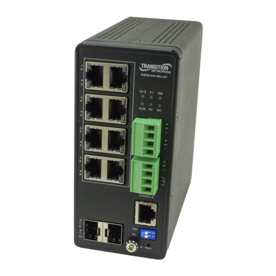
Transition Networks SISPM1040‐582‐LRT Install Guide Front Panel The SISPM1040‐582‐LRT front panel ports, LEDs, Power Input terminal block, DI/DO terminal block, CONSOLE port, DIP Switch, RESET button, and Ground screw are shown and described below. 33755 Rev. B https://www.transition.com Page 13 of 46 ... -
Page 14: Led Indicators
Transition Networks SISPM1040‐582‐LRT Install Guide LED Indicators The front panel LEDs provide for switch status monitoring. The types of LEDs include: Power LEDs: indicate if the switch is powered up correctly or not. System LED: indicates if the system is ready or not ready. Alarm LED: indicates if the system is normal or not. Ring Master LED and Rapid Chain LED: indicate if the Rapid Ring is ready or not ready. Port Status LEDs: indicates the current status of each port. Users can check these LEDs to understand the port status. The following tables detail the various LED functions. Table 1: Power LEDs LED Color State Description On The switch is powered ON correctly. P1 (Power 1) Green Off The switch is not receiving power from power 1. On The switch is powered ON correctly. P2 (Power 2) Green ... - Page 15 Transition Networks SISPM1040‐582‐LRT Install Guide You can check the port status by reading the LED behaviors per the table below. Table 4: Port Status LEDs LED Color State Description The port is enabled and established a link to connected device, and the Green On connection speed is 1000Mbps. The port is transmitting/receiving packets, and the connection speed is Green Blinking 1000Mbps. The port is enabled and established a link to connected device, and the RJ45 Amber On connection speed is 10/100Mbps. Ports The port is transmitting/receiving packets, and the connection speed is UP Amber Blinking 10/100Mbps. The port has no active network cable connected, or it is not established a link to ‐‐ ...
-
Page 16: Dip Switch For Ring Settings
Transition Networks SISPM1040‐582‐LRT Install Guide Table 5: Ring Master and Rapid Chain LED Description LED Color State Green On Ring Master has been detected in the switch. RM Amber On Ring Member has been detected in the switch. (Ring Master) ‐‐ Off Disable Green On Rapid Chain has been detected in the switch (Active path). On Rapid Chain has been detected in the switch (Backup path). RC Amber (Rapid Chain) Blinking Error: There is no corresponding Rapid Chain switch found. ‐‐ ... -
Page 17: Reset Button
Transition Networks SISPM1040‐582‐LRT Install Guide RESET Button By pressing the RESET button for certain period of time, you can perform the following tasks. Reset the Switch to reboot and get the switch back to the previously saved configuration settings. Restore the Switch to Factory Defaults: to restore the original factory default settings back to the switch. Note: Use the table below to determine which task is being performed by reading LED status while pressing the RESET button. Once the LED behaviors are correctly displayed, just release the RESET button. Table 6: RESET Button Operation Port Status LED Task Press RESET button for SYS LED Behavior Behavior Reset the Switch 2 ~ 7 seconds Blinking Green ALL LEDs are OFF Restore to Defaults 7 ~ 12 seconds Blinking Green ... -
Page 18: Installation
Transition Networks SISPM1040‐582‐LRT Install Guide 3. Installation Package Contents Carefully unpack the package contents in their final location. Verify that you have received the items below. One Switch with Terminal Block attached One Power Supply (packaged separately) One DB‐9 to RJ‐45 Cable Four adhesive rubber feet One Printed Quick Start Guide 19” Rack Mount brackets Contact your sales representative if any parts are missing or damaged. Please save the packaging for possible future use. Caution: The switch is an indoor device. If it is to be used with outdoor devices such as outdoor IP cameras or outdoor Wi‐Fi APs, then you are strongly suggested to install a surge protector or surge suppressor in order to protect the switch. Compliant with 802.3at in Environment A when using an isolated power supply. For 802.3at Environment B applications, i.e. building to building, copper to copper endpoint connections: 1) use an Ethernet network isolator module (PoE disabled), or 2) use mid‐span injector(s), e.g. MIL‐L100i, L1000i‐at, between this switch’s PSE port and link partner PD port. Warning: Safety First: Turn the power off before connecting or disconnecting modules or wires. The correct power supply voltage is listed on the product label. Check the voltage of your power source to make sure that you are using the correct voltage. Do NOT use a voltage greater than what is specified on the product label. ... -
Page 19: Mounting The Switch On A Din Rail
Transition Networks SISPM1040‐582‐LRT Install Guide Mounting the Switch on a DIN Rail 1. Attach the DIN Rail mounting kit to the rear panel of the chassis. Insert screws and tighten then with a screwdriver to secure the kit. 2. Insert the upper lip of the DIN rail into the DIN‐rail mounting kit and press the switch towards the DIN rail until it snaps into place. 3. Make sure that the switch is attached securely to DIN Rail. 33755 Rev. B https://www.transition.com Page 19 of 46 ... -
Page 20: Mounting The Switch On A Wall (Optional)
Transition Networks SISPM1040‐582‐LRT Install Guide Mounting the Switch on a Wall (Optional) 1. Attach the wall mounting plates to rear panel of the chassis. Insert screws and tighten them with a screwdriver to secure the plates. 2. Install user‐supplied screws on the appropriate location on the wall. 3. Make sure that the switch is attached securely to the wall. 33755 Rev. B https://www.transition.com Page 20 of 46 ... -
Page 21: Installing Sfp Modules
Transition Networks SISPM1040‐582‐LRT Install Guide Installing SFP Modules You can install or remove a mini‐GBIC SFP module from a SFP port without having to power off the switch. Note: The SFP ports should use UL Listed Optional Transceiver product, Rated 3.3Vdc, Laser Class 1. 1. Note the proper orientation and insert the module into the SFP port. 2. Press firmly to ensure that the module seats into the connector. Connecting Devices ... -
Page 22: Connecting The Di/Do (Digital Input / Digital Output) Relay
Transition Networks SISPM1040‐582‐LRT Install Guide Connecting the DI/DO (Digital Input / Digital Output) Relay + ‐ 1. Insert the negative (ground)/positive DI/DO Relay wires into the terminals, respectively. 2. To keep the DI/DO Relay wires from pulling loose, use a small flat‐blade screwdriver to tighten the wire‐clamp screws on the front of the Terminal Block connector. 3. Insert the Terminal Block connector prongs into the Terminal Block receptor. Note: Digital output (relay): 24VDC/1A Digital input: level 0 (Low) ‐> 0V to 6V, level 1 (High) ‐> 10V to 24V FAULT: The two contacts of the terminal block connector are used to detect user‐configured events. The two ... -
Page 23: Grounding Screw
Transition Networks SISPM1040‐582‐LRT Install Guide Grounding Screw ATTENTION: This case must be earth grounded. No DC input may be earth grounded. Use Isolated Power Supply. Grounding the Switch helps limit the effects of noise due to electromagnetic interference (EMI) via proper grounding. Always run the ground connection from the ground screw to a grounding surface before connecting the Switch to a power source. Wiring considerations: consider the following wiring recommendations: • Signal lines must not be directly connected to outdoor wiring. • Use separate paths or conduits to route wiring for power and device data cables. To avoid interference, wires with different signal characteristics route separately. If power wiring and device data cables must cross make sure that the wires are perpendicular at the intersection point. • Use the type of signal transmitted through a wire to determine which wires should be kept separate. The rule of thumb is wiring that shares similar electrical characteristics can be bundled together. • Keep input and output wiring separated. CAUTION: The Switch is intended to be grounded to a well‐grounded mounting surface such as a metal plate. Install the grounding wire prior to connecting any other device to the Switch. CAUTION: Be sure to disconnect the Switch from the power source before installing and wiring the device. Connecting P1 and P2 (54 VDC Power Inputs) V‐... -
Page 24: Power Supply Specifications
Transition Networks SISPM1040‐582‐LRT Install Guide Power Supply Specifications 480W Din Rail Power Supply (25160) TN Part number: 25160; see the 25160 webpage for product details. Rated Power: 480W Input 90 – 264VAC or 127 – 370VDC Output 48 – 55V Operating temp. – 25 ‐ +70◦C Description : AC‐DC Industrial DIN rail power supply; Output 48Vdc at 10A; Metal casing; Ultra slim width 85.5mm Net weight (grams) : 1820 Format : DIN rail Application : Installation UL 508; ITE EN/UL/IEC 60950 Output Power (W) : 480 Output Voltage (V) : 48 Output Current (A) : 10 Input Voltage (V) : 90‐264V; Universal Input 110/230V IP Rating : No IP Format : DIN rail Control Signals : DC OK ... -
Page 25: Power Supply Views (25160)
Transition Networks SISPM1040‐582‐LRT Install Guide Power Supply Views (25160) Front: Back: Top: Bottom: 33755 Rev. -
Page 26: Power Supply Dimensions (25160)
Transition Networks SISPM1040‐582‐LRT Install Guide Power Supply Dimensions (25160) Width : 85.5 mm (3.36 in.) Height : 125.2 mm (4.92 in.) Depth : 128.5 mm (5.05 in.) ADMISSIBLE DIN‐RAIL: TS35/7.5 OR TS35/15 33755 Rev. B https://www.transition.com Page 26 of 46 ... -
Page 27: Power Supply Pin Descriptions (25160)
Transition Networks SISPM1040‐582‐LRT Install Guide Power Supply Pin Descriptions (25160) Terminal Pin No. Assignment (TB1) Pin No. Assignment 1 FG 2 AC/N 3 AC/L Terminal Pin No. Assignment (TB2) Pin No. Assignment 1,2 DC OUTPUT +V 3,4 DC OUTPUT ‐V 5,6 Relay Contact ... -
Page 28: 240W Din Rail Power Supply (25104)
Transition Networks SISPM1040‐582‐LRT Install Guide 240W Din Rail Power Supply (25104) TN Part number: 25104. See the 25104 webpage for product details. Input: 85‐264 VAC, 124‐370 VDC Output: 48 ~ 55 VDC, 5A, 240 Watts Power Supply Features (25104) 94% High Efficiency 150% Peak Load Protected against: Short Circuit, Overload, Over Voltage, and Overheating. Convection air cooling DIN rail mountable UL 508 approved Full load burn in test RoHS compliant MTBF 169.3 Khrs Power Supply Specifications (25104) Power Output: ... -
Page 29: 4. Initial Switch Configuration
Transition Networks SISPM1040‐582‐LRT Install Guide 4. Initial Switch Configuration Initial Switch Configuration via Web Browser When you power up the switch the first time, the web UI displays a First Time Wizard displays. See the SISPM1040‐582‐LRT Web User Guide for more information. Initial Switch Configuration via CLI See the SISPM1040‐582‐LRT CLI Reference for more information. 33755 Rev. B https://www.transition.com Page 29 of 46 ... -
Page 30: 5. Troubleshooting, Warranty, Support And Compliance
Transition Networks SISPM1040‐582‐LRT Install Guide 5. Troubleshooting, Warranty, Support and Compliance Troubleshooting This section provides steps to troubleshoot problems by taking actions based on the suggested solutions. General Troubleshooting Most problems are caused by the following situations. Check for these items first when starting troubleshooting: 1. Make sure your switch model supports the feature or function attempted; see Key on page 5. 2. Verify the install process; see chapter 3. Installation on page 18. 3. Troubleshoot connected network devices to pinpoint the problem to the switch. 4. Connecting to devices that have a fixed full‐ duplex configuration. Make sure all devices connected to the Switch devices are configured to auto negotiate, or are configured to connect at half duplex. 5. Faulty or loose cables. Look for loose or obviously faulty connections. If they appear to be OK, make sure the connections are snug. If that does not correct the problem, try a different cable. 6. Non‐standard cables. Non‐standard and miswired cables may cause network collisions and other network problems, and can seriously impair network performance. Use a new correctly‐wired cable. A cable tester is a recommended tool for every Ethernet network installation. 7. Improper Network Topologies. Make sure you have a valid network topology. If you no longer experience the problems, the new topology is probably at fault. Also, make sure your network topology contains no data ... -
Page 31: Led Troubleshooting
Transition Networks SISPM1040‐582‐LRT Install Guide LED Troubleshooting The following table provides information for users to easily troubleshoot problems by taking actions based on the suggested solutions within. Table 7: Troubleshooting Symptom Possible Cause Suggested Solutions 1. Check if correct power cord is connected firmly to the switch and to the DC outlet socket. The switch is not 2. Perform power cycling the switch by unplugging and plugging SYSTEM LED is Off receiving power. the power cord back into the switch. 3. If the LED is still off, try to plug power cord into different DC outlet socket to make sure correct DC source is supplied. 1. Check if the cable connector plug is firmly inserted and locked into the port at both the switch and the connected device. The port is not 2. Make sure the connected device is up and running correctly. connected or the Port Up Status LED is Off 3. If the symptom still exists, try different cable or different port, ... -
Page 32: Poe Modes And Compliance
Transition Networks SISPM1040‐582‐LRT Install Guide PoE Modes and Compliance PoE History PoE first emerged to solve the problem of powering Voice over Internet Protocol (VoIP) phones. PoE gained momentum in 2001 and 2002, when WAP makers, and other manufacturers took advantage of the technique. IEEE 802.3af can use a single standard RJ45 connector and CAT 5 (or even CAT 3) cable. PoE+ (PoE Plus) provides extended support for new end devices with higher power requirements. The IEE 802.3at standard provides up to 30 W of power to include newer end devices such as IEEE 802.11n wireless access points, surveillance cameras, etc. PoE++ (IEEE 802.3bt): As manufacturers continued to advance the use of PoE, another option became available for PoE with greater output. PoE++ delivers up to 60 watts of power using the 802.3bt standard. PoE++ is delivered using the simultaneous transmission of Mode A and Mode B. PoE++ is ideal for IP surveillance cameras that require more throughput or a various other equipment such as LCD displays, computer workstations, and biomedical equipment. Min. cable type Cat5e; recommend Cat 6A cabling. PoE Standards Comparison PoE Type 1 / PoE+ Type 2 / 802.3bt Type 3 / 802.3bt Type 4 Property 802.3af PoE 802.3at PoE+ 802.3bt Type 3 802.3bt Type 4 ... -
Page 33: Poe Types
Transition Networks SISPM1040‐582‐LRT Install Guide PoE Types See below for PoE type, PD power, cabling, and classes. PD Type PD Power Cable Category Classes Type 1 up to 12.95 Cat 3 and Cat 5 2 pairs class 1‐2 Type 2 up to 25.5W Cat 5 2 pairs class 3‐4 Type 3 40 – 51 W Cat5e 4 pairs class 5‐6 Type 4 62 – 71 W Cat5e 4 pairs class 7‐8 Type 1 : Also known as PoE, 2‐pair PoE. Related standard: IEEE 802.3af. Maximum power to port: 15.4W. PoE Type 1 utilizes two pairs to connect many types of lower‐powered devices to the network. Based on the ... -
Page 34: Poe Classes
Transition Networks SISPM1040‐582‐LRT Install Guide PoE Classes PoE Classification is where the PSE detects the PD’s power requirements by using Physical Layer Classification or LLDP. The IEEE 802.3bt draft standard specifies mutual identification to address four‐pair operation. Additional clauses were added, defining the following: Class PSE Output Power[W] PD Input Power[W] PD Type Standard 0 15.4 12.95 1 1 4 3.84 1 IEEE 802.3af 2 7 6.49 1 3 15.4 12.95 1 ... -
Page 35: Mode A Vs. Mode B
Transition Networks SISPM1040‐582‐LRT Install Guide Mode A vs. Mode B Alternative A, also known as Mode A, uses the data pairs of an Ethernet link to deliver power. Data Pairs include pins 1,2 and 3,6. PSEs using Mode A supply a positive voltage to pins 1 and 2. Alternative B, also known as Mode B, uses the spare pairs to deliver power. Spare Pairs include pins 4,5 and 7,8. 802.3af/at Standard “compliant” vs "compatible" PDs Knowing the difference between PoE "compliant" devices and "compatible" devices can help avoid interoperability and connectivity issues. Compliant and compatible PoE devices are not held to the same 802.3af/at standard: • 802.3af/at “compliant” PDs fulfill the IEEE strict requirement to support both Mode A and Mode B power modes. • 802.3af/at "compatible" PDs typically can provide power using only Mode B. Typical PD Power Requirements ... -
Page 36: Ethernet And Poe Intra-Building Cabling Warnings
Transition Networks SISPM1040‐582‐LRT Install Guide Ethernet and PoE Intra-Building Cabling Warnings 1. Ethernet cables are intended for intrabuilding use only. Connecting your TN switch directly to Ethernet cables that run outside the building in which the switch is housed will void the user's warranty and could create a fire or shock hazard. 2. PoE cables are intended for intrabuilding use only. Connecting your TN switch directly to PoE cables that run outside the building in which the switch is housed will void the user's warranty and could create a fire or shock hazard. 3. For outdoor PoE applications, we recommend using Transition Networks' SI‐IES‐1200‐LRT Unmanaged Hardened PoE+ Injector or SI‐IES‐111D‐LRT Unmanaged Hardened PoE+ Injector/Converter Use of any other PoE injector will void the user's warranty and could create a fire or shock hazard. Legacy PD Detection / Capacitor Detection Legacy PDs refers to powered devices manufactured before the IEEE standard was finalized and do not have the expected PD signature required by the PSE's detection signal. Such PDs usually feature large capacitance as the ... -
Page 37: Poe/Poe+/Poe++ Comparison Chart
Transition Networks SISPM1040‐582‐LRT Install Guide PoE/PoE+/PoE++ Comparison Chart The table below compares the three types of PoE supported. Max. Twisted Power at Power at Max. Data Standard Type Standards Current pairs used Source Device Rate Ratified IEEE 802.3af PoE 350 mA 2 pairs 15.4 W 13 W 1000Base‐T 2003 (802.3at Type 1) ... -
Page 38: Term Definitions
Transition Networks SISPM1040‐582‐LRT Install Guide Term Definitions From Draft Standard for Ethernet Amendment 2: Power over Ethernet over 4 Pairs (IEEE 802.3bt) (See IEEE 802.3, Clause 145.) Ampacity: the maximum current, in ampere, that a conductor can carry continuously under the conditions of use without exceeding its temperature rating. Dual‐signature PD: A PD that has independent detection signatures, class signatures, and maintains power signatures on each pairset. Link section: the portion of the link between the PSE Power Interface (PI) and the PD PI. Pairset: Either of two valid 4‐conductor connections, Alternative A or Alternative B, as listed in IEEE 802.3, 145.2.4. The PSE Alternative A and Alternative B connections are referred to as Mode A and Mode B, respectively, at the PD. Power Sourcing Equipment (PSE): A DTE or midspan device that provides power to a single link section which may also carry data. Single‐signature PD: A PD that simultaneously shares the same detection signature, class signature, and maintains power signature between both pairsets. Type 1 PD: A PD that requests Class 0 to Class 3 during Physical Layer classification and that is not a PoDL PD. Type 1 PSE: A PSE that supports Class 0 to Class 3 power levels and provides power over 2 pairs. Type 2 PD: A PD that requests Class 4 during Physical Layer classification, supports 2‐Event Classification, and supports Data Link Layer classification. Type 2 PSE: A PSE that supports Class 0 to Class 4 power levels and provides power over 2 pairs. Type 3 PD: A single‐signature PD that requests Class 1 to Class 6, or a dual‐signature PD that requests Class 1 to ... -
Page 39: Network Safety
Transition Networks SISPM1040‐582‐LRT Install Guide Network Safety This subclause sets forth a number of recommendations and guidelines related to safety concerns. The list is neither complete nor does it address all possible safety issues. The designer is urged to consult the relevant local, national, and international safety regulations to verify compliance with the appropriate requirements. LAN cabling systems described in this clause are subject to at least four direct electrical safety hazards during their installation and use. These hazards are as follows: a) Direct contact between LAN components and power, lighting, or communications circuits. b) Static charge buildup on LAN cabling and components. c) High‐energy transients coupled onto the LAN cabling system. d) Voltage potential differences between safety grounds to which various LAN components are connected. Such safety hazards should be avoided or appropriately protected against for proper network installation and performance. In addition to provisions for proper handling of these conditions in an operational system, special measures should be taken to verify that the intended safety features are not negated during installation of a new network or during modification of an existing network. Patch Panel Considerations It is possible that the current carrying capability of a cabling cross‐connect may be exceeded by a PSE. The designer should consult the manufacturer’s specifications to verify compliance with the appropriate requirements. Electromagnetic Emissions The PD and PSE powered cabling link shall comply with applicable local and national codes for the limitation of electromagnetic interference. Temperature and Humidity The PD and PSE powered cabling link segment is expected to operate over a reasonable range of environmental conditions related to temperature, humidity, and physical handling. Specific requirements and values for these ... -
Page 40: Backward Compatibility
Transition Networks SISPM1040‐582‐LRT Install Guide Backward Compatibility Although new features were added, higher power is supported and some algorithms were changed to ensure interoperability. The idea is that the system will work with legacy Type 1 and Type 2 devices. It should work automatically, as long as the PSE is capable (in terms of power) of supporting the PD and both are standard compliant. Should the PD require higher power (IEEE 802.3bt PD) and the PSE cannot support it (IEEE 802.3af PSE), the PD will either remain off or it will turn on and consume only the power available from the PSE. The table on PoE backward compatibility is updated every six weeks, after the IEEE802.3bt Task Force meetings take place. For the latest information, see http://www.microsemi.com/designsupport/poe‐and‐poh‐technology#resources. 33755 Rev. B https://www.transition.com Page 40 of 46 ... -
Page 41: Recording Device And System Information
After performing the troubleshooting procedures, and before calling or emailing Technical Support, please record as much information as possible in order to help the Transition Networks Tech Support Specialist. 1. Select the Configuration > System > Information menu path. From the CLI, use the show commands to gather the information below or as requested by the TN Support Specialist. -
Page 42: Limited Lifetime Warranty
Transition Networks SISPM1040‐582‐LRT Install Guide Limited Lifetime Warranty To return a defective product for warranty coverage, contact Transition Networks’ technical support department for a return authorization number. Contact Us Technical Support Technical support is available 24‐hours a day US and Canada: 1‐800‐260‐1312 International: 00‐1‐952‐941‐7600 Main Office tel: +1.952.941.7600 | toll free: 1.800.526.9267 | fax: 952.941.2322 sales@transition.com | techsupport@transition.com | customerservice@transition.com Address Transition Networks ... -
Page 43: Declaration Of Conformity (Doc)
Transition Networks SISPM1040‐582‐LRT Install Guide Declaration of Conformity (DoC) Class I, Division 2 / classe I, division 2 Warning and Caution ‐ Proper Installation and Operation (English) These devices are open‐type devices that are to be installed in an enclosure only accessible with the use of a tool, suitable for the environment. This equipment is suitable for use in Class I, Division 2, Groups A, B, C, and D or non‐hazardous locations only. WARNING – EXPLOSION HAZARD. DO NOT DISCONNECT WHILE THE CIRCUIT IS LIVE OR UNLESS THE AREA IS FREE OF IGNITIBLE CONCENTRATIONS. Avertissement et mise en garde ‐ Installation et fonctionnement corrects (français) Ces périphériques sont des périphériques de type ouvert qui doivent être installés dans un enceinte uniquement accessible à l'aide d'un outil, adapté à environnement. Cet équipement peut être utilisé dans la classe I, division 2, groupes A, B, C, et D ou des emplacements non dangereux seulement. AVERTISSEMENT ‐ RISQUE D'EXPLOSION. NE PAS SE DÉCONNECTER LORSQUE LE CIRCUIT EST VIVANT OU À MOINS QUE LA ZONE NE SOIT LIBRE DE CONCENTRATIONS IGNIFIABLES. High Risk Activities Disclaimer Components, units, or third‐party products used in the product described herein are NOT fault‐tolerant and are ... -
Page 44: Cautions And Warnings
Transition Networks SISPM1040‐582‐LRT Install Guide Cautions and Warnings Definitions Cautions indicate that there is the possibility of poor equipment performance or potential damage to the equipment. Warnings indicate that there is the possibility of injury to person. Cautions and Warnings appear here and may appear throughout this manual where appropriate. Failure to read and understand the information identified by this symbol could result in poor equipment performance, damage to the equipment, or injury to persons. Cautions While installing or servicing the power module, wear a grounding device and observe all electrostatic discharge precautions. Failure to observe this caution could result in damage to, or failure of the power module. Warnings Warning: Do not connect the power module to an external power source before installing it into the chassis. Failure to observe this warning could result in an electrical shock, even death. WARNING: The power module has a provision for grounding. Equipment grounding is vital to ensure safe operation. The installer must ensure that the power module is properly grounded during and after installation. Failure to observe this warning could result in an electric shock, even death. WARNING: A readily accessible, suitable National Electrical Code (NEC) or local electrical code approved disconnect device and branch‐circuit protector must be part of the building's installed wiring to accommodate ... -
Page 45: Electrical Safety Warnings
Transition Networks SISPM1040‐582‐LRT Install Guide Electrical Safety Warnings Electrical Safety IMPORTANT: This equipment must be installed in accordance with safety precautions. Elektrische Sicherheit WICHTIG: Für die Installation dieses Gerätes ist die Einhaltung von Sicherheitsvorkehrungen erforderlich. Elektrisk sikkerhed VIGTIGT: Dette udstyr skal installeres i overensstemmelse med sikkerhedsadvarslerne. Elektrische veiligheid BELANGRIJK: Dit apparaat moet in overeenstemming met de veiligheidsvoorschriften worden geïnstalleerd. Sécurité électrique IMPORTANT: Cet équipement doit être utilisé conformément aux instructions de sécurité. Sähköturvallisuus TÄRKEÄÄ: Tämä laite on asennettava turvaohjeiden mukaisesti. Sicurezza elettrica IMPORTANTE: questa apparecchiatura deve essere installata rispettando le norme di sicurezza. Elektrisk sikkerhet VIKTIG: Dette utstyret skal installeres i samsvar med sikkerhetsregler. Segurança eléctrica IMPORTANTE: Este equipamento tem que ser instalado segundo as medidas de precaução de segurança. ... - Page 46 Transition Networks SISPM1040‐582‐LRT Install Guide Transition Networks 10900 Red Circle Drive Minnetonka, MN 55343, U.S.A. tel: +1.952.941.7600 | toll free: 1.800.526.9267 | fax: 952.941.2322 sales@transition.com | techsupport@transition.com | customerservice@transition.com Copyright© 2018 Transition Networks. All rights reserved. Printed in the U.S.A. SISPM1040‐582‐LRT Install Guide, 33755 Rev. B 33755 Rev. B https://www.transition.com Page 46 of 46 ...
Need help?
Do you have a question about the SISPM1040-582-LRT and is the answer not in the manual?
Questions and answers