
Related Manuals for Transition Networks SISTF1010-180-LRT


Summary of Contents for Transition Networks SISTF1010-180-LRT
- Page 1 SISTF1010-180-LR(T) 10/100Base-TX Industrial Unmanaged Switch Installation Manual Rev. A 6-July-2007...
-
Page 3: Table Of Contents
Warnings... vi Section I ...1 SISTF1010-180 Industrial Unmanaged Switch...1 In this section ...1 General description...2 Overview ...2 Features...2 SISTF1010-180 Industrial Unmanaged Switch part numbers ...3 Standard models ...3 Package contents ...4 Package contents...4 Physical description ...5 Physical dimensions...5 Front panel...5 Bottom panel...6... - Page 4 Transition Networks Section IV:...20 Cable Specifications...20 Introduction ...20 In this section ...20 Copper (RJ-45) cable specifications ...21 Copper cabling...21 Copper cable specifications ...21 RJ-45 pinouts...21 Section V:...22 Troubleshooting...22 Introduction ...22 In this section ...22 Troubleshooting problem and corrective action table ...23 Section VI:...24...
-
Page 5: Trademark, Copyright, And Product Classification Information
All trademarks and registered trademarks are the property of their respective owners. Copyright © 2007 Transition Networks: All rights reserved. No part of this work may be reproduced or restrictions used in any form or by any means—graphic, electronic, or mechanical—without written permission from Transition Networks. -
Page 6: About This Product And Manual
Term/usage In this manual, the term “Industrial Switch” (first letter upper case) refers to the SISTF1010-180-LR(T) 10/100Base-TX Industrial Unmanaged Switch. About this This manual provides instructions on how to install, configure, and operate the manual SISTF1010-180-LR(T) 10/100Base-TX Industrial Unmanaged Switch. -
Page 7: Cautions And Warnings
Cautions Cautions indicate the possibility of damage to equipment. CAUTION Make sure that the Industrial Switch is mounted with proper space around it for ventilation (heat dissipation). Failure to observe this caution could result in damage to the Industrial Switch. - Page 8 Warnings Warnings indicate the possibility of injury to persons. WARNING Be sure to disconnect power before installing and wiring the Industrial Switch. Failure to observe this warning could result in an electrical shock. WARNING Use of controls, adjustments or the performance of procedures other than those specified herein may result in hazardous radiation exposure.
-
Page 9: Section I
SISTF1010-180 Industrial Unmanaged Switch In this section These are the topics: General description SISTF1010-180 Industrial Unmanaged Switch model numbers Package Contents Physical Description Section I Topic See Page... -
Page 10: General Description
Transition Networks General description Overview The SISTF1010-180 Industrial Unmanaged Switch can help aggregate and transport data from copper-based industrial networking and communication devices. Each Industrial Switch can connect to either 10Base-T or 100Base-TX copper ports and is offered in two distinct... -
Page 11: Sistf1010-180 Industrial Unmanaged Switch Part Numbers
SPS-UA12DHT-xx Note: Replace the xx in the part number above with one of the following identifiers to match the region where the Industrial Switch will be installed: NA = North America UK = United Kingdom 24-Hour Technical Support: 1-800-260-1312 International: 00-1-952-941-7600... -
Page 12: Package Contents
Barrel connector interface cable Compare the package contents of your industrial Switch with the standard checklist above. If any item is damaged or missing, please contact Transition Networks Technical Support. SISTF1010-180-LR(T) Industrial Unmanaged Switch For external AC/DC power supply (sold separately) -
Page 13: Physical Description
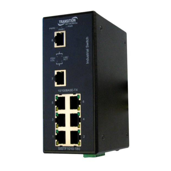
Width: 2.1” [54mm] Physical dimensions Height: 5.3” [135mm] Depth: 4.1” [105mm] Front panel The front panel of the Industrial Switch is shown in Figure 1 with corresponding descriptions listed below: 10/100Base-TX UTP ports (RJ-45) 10/100Base-TX UTP ports (RJ-45) Figure 1: SISTF1010-180-LR(T) Industrial Switch (Front View) -
Page 14: Bottom Panel
Transition Networks Physical description, continued Bottom panel The bottom view of the Industrial Switch is shown in Figure 2 with corresponding descriptions listed below: Secondary power input terminals (2) Figure 2: SISTF1010-180-LR(T) Industrial Switch (Bottom View) Back panel The back view of the Industrial Switch is shown in Figure 3 with corresponding descriptions... -
Page 15: Section Ii
In this section These are the topics: DIN rail mounting Wall mounting Grounding the Industrial Switch Connecting power to the Industrial Switch Connecting copper cable Light Emitting Diodes (LEDs) Section II Installation Topic See Page... -
Page 16: Din Rail Mounting
Transition Networks DIN rail mounting DIN rail clip The Industrial Switch includes an aluminum DIN Rail Clip attached to the rear panel. Verify the clip is attached and oriented as pictured in Figure 4 below. Figure 4: Mounted DIN Rail Clip... -
Page 17: Din Rail Mounting
Align and then position DIN-Rail-clip spring to the top of the DIN rail as shown in Figure 5, step (a). Press DOWN on the Industrial Switch and then IN to snap it into place on the DIN Rail. See Figure 5, step (b). -
Page 18: Wall Mounting
The Industrial Switch includes a wall mount bracket and screws in the contents of the shipping bracket package. The wall mount bracket can be attached to the rear panel of the Industrial Switch to enable mounting to a vertical surface such as the wall of an enclosure. Locate the bracket (1) and screws (6) and follow the steps below to install the bracket on the Industrial Switch. -
Page 19: Grounding The Industrial Switch
(EMI) via proper grounding. Always run the ground connection from the ground screw to a grounding surface before connecting the Industrial Switch to a DC power source. See Figure 7. Figure 7: Industrial Switch Ground Screw (Bottom Panel) -
Page 20: Connecting Power To The Industrial Switch
• Power is supplied through an external 12-48 VDC power source. Check the Technical Specification section for details about the DC power input voltage. • The Industrial Switch does not include a power switch; therefore, plugging a wired and active terminal-block plug into its terminal block will immediately power ON the unit. -
Page 21: Terminal-Block Wiring
The 6-position terminal-block plug is constructed (keyed) to mate with the Industrial Note: Switch terminal block. When wiring the plug for power, use the polarity markings next to the terminal block and on top of the plug to ensure proper connection. - Page 22 Terminal-block wiring (continued) Step Action Insert the terminal block plug into the Industrial Switch’s terminal block, as shown in Figure 10. Figure 10: Wired Terminal Block Plug Inserted Into Industrial Switch Make sure that the DC power source is stable and clean.
-
Page 23: Barrel Connector Interface Cable
Connecting power to the Industrial Switch, continued Barrel connector A barrel connector interface cable is included with the Industrial Switch and can be used to interface cable convert the barrel connector output of an external AC/DC power supply over to a wire interface that can then be inserted into the terminal block following the instructions and figure 9, both located on page 13 of this manual. -
Page 24: Connecting Copper Cables
Transition Networks Connecting copper cables Copper cable To connect the copper cable to the Industrial Switch and other equipment, do the following: installation Step Action Locate or build 10Base-T or 100Base-TX copper cables with male, RJ-45 connectors installed at both ends. -
Page 25: Light Emitting Diodes (Leds)
Light Emitting Diodes (LEDs) LEDs The Industrial Switch has LED indicators located on its front panel. The LEDs present at-a- glance network status, and provide real-time connectivity information. Figure 14 shows the LEDs and a chart that explains the function of each. -
Page 26: Section Iii
Introduction This section provides an explanation of the advanced features on the Industrial Switch. In this section These are the topics: AutoCross Auto-Negotiation Pause Section III: Advanced Features Topic See Page... -
Page 27: Advanced Features
Auto-Negotiation allows devices to perform automatic configuration to achieve the best (IEEE 802.3u) possible mode of operation over a link. The Industrial Switch will broadcast its speed (10Mbps, 100Mbps) and duplex (half/full) capabilities to other devices and negotiate the best mode of operation between the two devices. -
Page 28: Cable Specifications
Transition Networks Introduction This section provides copper cable specifications. In this section These are the topics: UTP cable specifications SISTF1010-180-LR(T) Industrial Unmanaged Switch Section IV: Cable Specifications Topic 24-Hour Technical Support: 1-800-260-1312 International: 00-1-952-941-7600 See Page... -
Page 29: Copper (Rj-45) Cable Specifications
Transmit Data + (TD+) Transmit Data - (TD-) Figure 17: RJ-45 Connector Pin Assignment Chart The Industrial Switch is configured as a MDI-X device. Note: 24-Hour Technical Support: 1-800-260-1312 International: 00-1-952-941-7600 feature determines the characteristics of the cable connection and Category 5 (minimum) 22.0 dB /100m @ 100 MHz... -
Page 30: Section V
Transition Networks Introduction This section provides basic troubleshooting information for the Industrial Switch via a problem and corrective action table. The problems are stated in the problem column and the action(s) to take for the problem is stated in the corrective action column. If the corrective measures listed do not correct the problem, contact our 24-Hour Technical Support department at 1-800- 260-1312, International: 00-1-952-941-7600. -
Page 31: Troubleshooting Problem And Corrective Action Table
• Contact Technical Support. US/Canada: 1-800-260-1312, International: 00-1-952-941-7600 • Check that the power is turned ON. • Verify that the cable at both ends is properly inserted into the UTP port • Contact Technical Support. US/Canada: 1-800-260-1312, International: 00-1-952-941-7600 Transition Networks Potential Solution... -
Page 32: Section Vi
Contact Us, Warranty, & Compliance Information Introduction This section explains how to contact Transition Networks via Phone, fax, email, and direct mail. It also explains: • What the warranty covers • Who to contact to return product • How and where to return the product •... -
Page 33: Contact Us
United States: International: Live Web chat Chat live via the Web with a Transition Networks Technical Support Specialist. Log onto www.transition.com and click the Transition Now link. Web-based Transition Networks provides 8-10 seminars per month via live web-based training. -
Page 34: Warranty
Transition Networks Warranty Limited lifetime Effective for products shipped May 1, 1999 and after, every Transition Networks’ labeled warranty product will be free from defects in material and workmanship for its lifetime. This warranty covers the original user only and is not transferable. -
Page 35: Customer Pays Non-Compliant Return Costs
All warranty claims are subject to the restrictions and conventions set forth by this products document. Transition Networks reserves the right to charge for all testing and shipping incurred, if after testing, a return is classified as “No Problem Found.” This warranty is This warranty is your only remedy. -
Page 36: Compliance Information
Compliance information Compliances CISPR22/EN5022 Class A + EN55024; EN60950 Class A; FCC Class A; CE Mark UL Listed; The following part numbers are UL Listed: SISTF1010-180-LR, SISTF1010-180-LRT. C-UL Listed (Canada) FCC Regulations This equipment has been tested and found to comply with the limits for a Class A digital device, pursuant to part 15 of the FCC rules. - Page 37 In accordance with European Union Directive 2002/96/EC of the European Parliament and of Regulations, the Council of 27 January 2003, Transition Networks will accept post usage returns (continued) of this product for proper disposal. The contact information for this activity can be found in the ‘Contact Us’...
-
Page 38: Appendix A
Technical Specifications SISTF1010-180-LR(T) specifications, notices, and warnings Parameter Standards Regulatory Compliance for Emissions Safety Compliance EMI Compliance Environmental Compliance Ports Max Distance Max Data Rate Signals MAC Addresses Memory Buffer Transfer Rate Packet Throughput Back plane Power Consumption Ingress Protection MTBF Input Power Dimensions... -
Page 39: Notices
Notices • The information in this user’s guide is subject to change. For the most up-to-date information on the SISTF1010-180-LR(T) Industrial Unmanaged Switch, please refer to the user’s guide on-line at: www.transition.com. • Product is certified by the manufacturer to comply with DHHS Rule 21/CFR, Subchapter J applicable at the date of manufacture.
Need help?
Do you have a question about the SISTF1010-180-LRT and is the answer not in the manual?
Questions and answers