Table of Contents
Advertisement
Quick Links
Transition Networks
SISPM1040‐3xxx‐L Install Guide
SISPM1040‐3xxx‐L
Rack Mount Industrial Ethernet Switches
SISPM1040‐3166‐L Managed Hardened PoE+ Switch, (16) 10/100/1000Base‐T PoE+ ports
+ (4) 100/1000Base‐X SFP/RJ‐45 Combo + (2) 1G/10G SFP+
SISPM1040‐3248‐L Managed Hardened PoE+ Switch, (24) 10/100/1000Base‐T PoE+ ports
+ (4) 100/1000Base‐X SFP/RJ‐45 Combo + (4) 1G/10G SFP+
Install Guide
33762 Rev. B
33762 Rev. B
https://www.transition.com
Page 1 of 50
Advertisement
Table of Contents
Troubleshooting

Related Manuals for Transition Networks SISPM1040-3-L Series


Summary of Contents for Transition Networks SISPM1040-3-L Series
- Page 1 Transition Networks SISPM1040‐3xxx‐L Install Guide SISPM1040‐3xxx‐L Rack Mount Industrial Ethernet Switches SISPM1040‐3166‐L Managed Hardened PoE+ Switch, (16) 10/100/1000Base‐T PoE+ ports + (4) 100/1000Base‐X SFP/RJ‐45 Combo + (2) 1G/10G SFP+ SISPM1040‐3248‐L Managed Hardened PoE+ Switch, (24) 10/100/1000Base‐T PoE+ ports + (4) 100/1000Base‐X SFP/RJ‐45 Combo + (4) 1G/10G SFP+ Install Guide 33762 Rev. B...
- Page 2 Transition Networks SISPM1040‐3xxx‐L Install Guide Safety Warnings and Cautions These products are not intended for use in life support products where failure of a product could reasonably be expected to result in death or personal injury. Anyone using this product in such an application without express written consent of an officer of Transition Networks does so at their own risk, and agrees to fully indemnify Transition Networks for any damages that may result from such use or sale. Attention: this product, like all electronic products, uses semiconductors that can be damaged by ESD (electrostatic discharge). Always observe appropriate precautions when handling. NOTE: Emphasizes important information or calls your attention to related features or instructions. WARNING: Alerts you to a potential hazard that could cause personal injury. CAUTION: Alerts you to a potential hazard that could cause loss of data, or damage the system or equipment. SISPM1040‐3xxx‐L Install Guide, 33762 Rev. B Record of Revisions Rev Date Description of Changes A 10/25/18 Release at FW v8.40.397. B 4/9/19 Add SISPM1040‐3166‐L, DHCP Per Port, and PS‐DC‐500‐56xxT Power Supply at FW v8.40.684 / HWv1.01. Trademark notice: All trademarks and registered trademarks are the property of their respective owners. All other products ...
-
Page 3: Table Of Contents
Transition Networks SISPM1040‐3xxx‐L Install Guide Contents Safety Warnings and Cautions ........................... 2 Chapter 1 ‐ Introduction ............................ 5 Key Features ................................ 5 Benefits .................................. 5 Ordering Information ............................... 6 Specifications ................................ 6 Software Features ..............................15 Applications ................................19 Front Panels ................................20 LED Descriptions ..............................21 Reset Button...............................22 Back Panels ................................23 Manual Overview ..............................24 Related Manuals ..............................24 ... - Page 4 Transition Networks SISPM1040‐3xxx‐L Install Guide LED Troubleshooting ..............................41 Record Device and System Information .........................43 Device Label and Packaging Label ..........................44 Chapter 5 ‐ Regulatory and Safety Information .................... 45 Compliance and Safety Statements ........................45 Declaration of Conformity .............................45 Class I, Division 2 / classe I, division 2 ........................46 High Risk Activities Disclaimer ..........................46 Cautions and Warnings ............................46 Electrical Safety Warnings ............................47 Chapter 6 ‐ Service, Warranty & Tech Support .................... 48 Warranty ................................48 Contact Us ................................49 33762 Rev. B https://www.transition.com Page 4 of 50...
-
Page 5: Chapter 1 - Introduction
Transition Networks SISPM1040‐3xxx‐L Install Guide Chapter 1 ‐ Introduction The SISPM1040‐3xxx‐L switches are next‐generation rack mount industrial grade Ethernet switches offering powerful L2 and basic L3 features with advanced functionality and usability. In addition to extensive management features, the SISPM1040‐3xxx‐L also provide Carrier Ethernet features such as OAM, CFM, ERPS, EPS, and PTPv2 which makes it suitable for industrial and Carrier Ethernet applications. The SISPM1040‐3248‐L delivers 24 (10M/100M/1G) RJ45/PoE+ (support 802.3at/af, and total up to 250W/370W) ports, 4 GbE SFP ports, 2/4 GbE/10G SFP+ ports and one RJ45 Console port. The SISPM1040‐3166‐L provides (16) 10/100/1000Base‐T PoE+ ports, (4) 100/1000Base‐X SFP/RJ‐45 Combo and (2) 1G/10G SFP+ ports. Key Features DMS (Device Management System) built in Compliant with IEEE 802.3af PoE and 802.3at PoE+ PoE Configuration, PoE Scheduling, PoE Power Delay, and PoE Auto Power Reset Carrier Ethernet features for easier manageability, security and QoS IEEE 1588v2 PTP (TC) IEEE 802.3ah OAM IEEE 802.1ag CFM (ITU‐T Y.1731 Performance monitoring) ITU‐T Y.1564 (RFC2544) Ethernet Service Activation Test ... -
Page 6: Ordering Information
Transition Networks SISPM1040‐3xxx‐L Install Guide Ordering Information SISPM1040‐3248‐L 24‐port Gigabit PoE+, 4 100/1000 SFP, 4 1G/10G SFP+, 370 Watts SISPM1040‐3166‐L 16‐ port Gigabit PoE+, 4 100/1000 SFP, 2 1G/10G SFP+, 250 Watts PS‐DC‐500‐56xxT 500W Standalone Power Supply Input 85‐264 VAC, 124‐370 VDC; Output: 48 ~ 55 VDC, 5A, 240 Watts (Optional 25104 Second Power Supply). Input: 90‐264 VAC, 127‐370 VDC; Output: 48 ~ 55 VDC, 10A, 480 Watts (Optional 25160 Second Power Supply). SISPM1040‐3248‐L‐xx Optional Power Cord; order separately where xx = NA, JP, etc. SFPs See Transition Networks SFP webpage. Specifications Port Configuration Total RJ45 RJ45/SFP Combo Uplinks SFP+ Model Console Ports ... - Page 7 Transition Networks SISPM1040‐3xxx‐L Install Guide Voltage and Frequency Model AC Input Voltage and Frequency DC Input Voltage SISPM1040‐3248‐L 100‐250 VAC, 50~60 Hz 52 – 57 VDC SISPM1040‐3166‐L PoE Power Model Available PoE Power # of Ports that Support PoE (15.4W) and PoE+ (30.0W) 370W (DC Input) Each of port 1‐ 24 supports PoE/ PoE+ within available PoE Power 370 Watts (PoE power not available with use of AC power supply). SISPM1040‐3248‐L Max PoE Budget 15 Watts for (24) ports simultaneously. 30 Watts for (12) ports simultaneously. 250W (DC Input) Each of port 1‐ 16 support PoE/ PoE+ within available PoE Power Max PoE Budget 250 Watts (PoE power not available with use of AC SISPM1040‐3166‐L power supply) Max PoE Budget ...
- Page 8 Transition Networks SISPM1040‐3xxx‐L Install Guide MTBF MTBF at 25.00 deg. MTBF at 75.00 deg. Model Environment GB, GC ‐ Ground Benign, Environment GB, GC ‐ Ground Benign, Controlled Controlled SISPM1040‐3248‐L 229,072 Hours 46,858 Hours SISPM1040‐3166‐L Power Consumption : SISPM1040‐3166‐L Maximum Power Consumption (without PoE): 36 Watts SISPM1040‐3248‐L Maximum Power Consumption (without PoE): 36 Watts No Load: Voltage Current Watt 12V 1.2A 14.4W Full Load: Test Voltage ...
- Page 9 Transition Networks SISPM1040‐3xxx‐L Install Guide PoE Power: DC Current DC DC Power Operating Status Consumption Voltage Consumption BTU/hr Interface (A) (V) (W) Non‐loading None 0.07 54.7 3.83 13.06 1G TP Port x 24 Standby mode 1G SFP x 4 6.80 54.7 371.96 1268.38 10G SFP x 4 ...
- Page 10 Transition Networks SISPM1040‐3xxx‐L Install Guide 54V DC DC Current DC DC Power Operating Status Consumption Voltage Consumption Interface (A) (V) (W) Non‐loading None 0.43 54 23.22 1G TP Port x 24 Standby mode 1G SFP x 4 7.96 54 429.84 10G SFP x 4 1G TP Port x 24 Full‐loading 1G SFP x 4 8.05 ...
- Page 11 Transition Networks SISPM1040‐3xxx‐L Install Guide AC Power Consumption: AC power consumption measured after 60 minutes under full loading with wire speed forwarding. 1. 100V AC Input AC Current AC Voltage Power Apparent Real Power Status Operating Interface Consumption (V) Factor Power (VA) (W) ...
- Page 12 Transition Networks SISPM1040‐3xxx‐L Install Guide 3. 220V AC Input AC Current AC Voltage Power Apparent Real Power Status Operating Interface Consumption (V) Factor Power (VA) (W) (A) Non‐loading None 220 0.10 0.72 22.00 15.84 Non‐PoE 1G TP Port x 24 Standby mode 1G SFP x 4 220 0.17 0.81 ...
- Page 13 Transition Networks SISPM1040‐3xxx‐L Install Guide AC and DC Power AC 110V + DC 52V DC Current DC DC Power Operating Status Consumption Voltage Consumption Interface (A) (V) (W) Non‐loading None 0.43 52 23.22 1G TP Port x 24 Standby mode 1G SFP x 4 7.96 52 429.84 10G SFP x 4 1G TP Port x 24 Full‐loading 1G SFP x 4 ...
- Page 14 Transition Networks SISPM1040‐3xxx‐L Install Guide AC 110V + DC 57V DC Current DC DC Power Operating Status Consumption Voltage Consumption Interface (A) (V) (W) Non‐loading None 0.43 57 23.22 1G TP Port x 24 Standby mode 1G SFP x 4 7.96 57 429.84 10G SFP x 4 1G TP Port x 24 Full‐loading 1G SFP x 4 ...
-
Page 15: Software Features
Transition Networks SISPM1040‐3xxx‐L Install Guide Software Features Layer 2 Switching Standard Spanning Tree 802.1d Spanning Tree Rapid Spanning Tree (RSTP) 802.1w Protocol (STP) Multiple Spanning Tree (MSTP) 802.1s Trunking Link Aggregation Control Protocol (LACP) IEEE 802.3ad Supports up to 4K VLANs simultaneously (out of 4096 VLAN IDs) Port‐based VLAN 802.1Q tag‐based VLAN MAC‐based VLAN VLAN Management VLAN Private VLAN Edge (PVE) Q‐in‐Q (double tag) VLAN ... - Page 16 Transition Networks SISPM1040‐3xxx‐L Install Guide VLAN. Supports multiple uplinks Locks MAC addresses to ports, and limits the number of learned MAC addresses Port Security Prevents illegal IP address from accessing to specific port in the switch IP Source Guard Supports RADIUS and TACACS+ authentication. Switch as a client RADIUS/ TACACS+ Prevents traffic on a LAN from being disrupted by a broadcast, multicast, or unicast Storm Control storm on a port DHCP Snooping A feature acts as a firewall between untrusted hosts and trusted DHCP servers Supports up to 256 entries. Drop or rate limitation based on: Source and destination MAC, VLAN ID or IP address, protocol, port Differentiated services code point (DSCP) / IP precedence TCP/ UDP source and destination ports ACLs 802.1p priority Ethernet type Internet Control Message Protocol (ICMP) packets TCP flag ...
- Page 17 Transition Networks SISPM1040‐3xxx‐L Install Guide The industry standard for monitoring high speed switched networks. It gives s‐Flow complete visibility into the use of networks enabling performance optimization, accounting/billing for usage, and defense against security threats Used by network devices for advertising their identities, capabilities, and IEEE 802.1ab (LLDP) neighbors on an IEEE 802ab local area network Support LLDP‐MED extensions Web GUI Interface Built‐in switch configuration utility for browser‐based device configuration CLI Configure/manage switches in command line interface modes Dual Image Independent primary and secondary images for backup while upgrading SNMP version1, 2c and 3 with support for traps, and SNMP version 3 user‐based SNMP security model (USM) Web browser upgrade (HTTP/ HTTPs) and TFTP Firmware Upgrade Upgrade via console port as well ...
- Page 18 Transition Networks SISPM1040‐3xxx‐L Install Guide 1588v2 PTP. OAM (IEEE802.3ah), CFM (IEEE802.1ag), PM (ITU‐T Y.1731), ELPS (ITU‐T Carrier Ethernet G.8031) , ERPS (ITU‐T G.8032), Y.1564 Ethernet OAM IEEE 802.3ah Link Supports IEEE 802.3ah Ethernet OAM (Operations, Administration & Management) OAM IEEE 802.1ag & ITU‐T Supports IEEE 802.1ag Ethernet CFM (Connectivity Fault Management) Y.1731 Flow OAM Supports ITU‐T Y.1731 PM (Performance Monitoring) Support RFC2544 Ethernet Service Activation Test Benchmarking Methodology: ITU‐T Y.1564 Throughput, Latency, Frame loss rate, Back‐to‐back frames Test Power over Ethernet (PoE) Port Configuration Supports per port PoE configuration function PoE Scheduling Supports per port PoE scheduling to turn on/off the PoE devices (PDs). PoE Auto Checking Auto Power Reset checks the link status of PDs. Reboot PDs if there are no responses. The switch provides power to PDs based on delay time when PoE switch boots up, in Power Delay order to protect switch from misuse of the PDs. Device Management System (DMS) ...
-
Page 19: Applications
Transition Networks SISPM1040‐3xxx‐L Install Guide Applications High‐resolution IP camera, IP PTZ camera High‐performance wireless access points Intelligent Transportation System (ITS) Oil and gas field sites 33762 Rev. B https://www.transition.com Page 19 of 50... -
Page 20: Front Panels
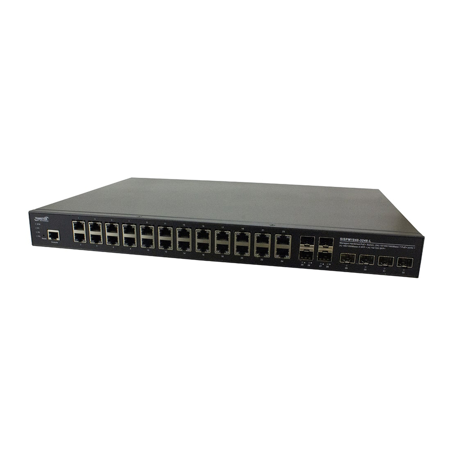
Transition Networks SISPM1040‐3xxx‐L Install Guide Front Panels The SISPM1040‐3248‐L front panel is shown below: The SISPM1040‐3166‐L front panel is shown below: 33762 Rev. B https://www.transition.com Page 20 of 50... -
Page 21: Led Descriptions
Transition Networks SISPM1040‐3xxx‐L Install Guide LED Descriptions The LEDs on the front panel provide switch status checking and monitoring. There are three types of LEDs: System LED: Indicates if the switch is powered up correctly or not, or, indicates if there is a system alarm triggered for troubleshooting. Power LEDs (P1/P1: DC LED, P3: AC LED): Indicate if the switch is powered up correctly or not. Port Status LEDs: Indicate the current status of each port. System LEDs: LED Color Function Light off: All Power Off Green Light: Switch FW Bootup is Ready SYS Green Blinking: System Booting Green/Red (System) Red Light: Minor Alarms Red Blinking: Major Alarms: an abnormal state, such as exceeding operating temperature range, has been detected in the switch. P1 Light off: Power 1 Off; The switch is not receiving power from DC power. Green (DC Power 1) Green Light on: Power 1 on; the switch is powered ON correctly. Light off: Power 2 Off; The switch is not receiving power from DC power. P2 ... -
Page 22: Reset Button
Transition Networks SISPM1040‐3xxx‐L Install Guide Port Status LEDs: LED Color Function Light off: port disconnected or link failed Green Light on: link‐up (1G) TP Port Green/Amber Amber Light on: link‐up (10/100M) Blinking: activity (receiving or transmitting data) Light off: port disconnected or link failed Green Light on: link‐up (1G) SFP Port Green/Amber Amber Light on: link‐up (100M) Blinking: activity (receiving or transmitting data) Light off: port disconnected or link failed Blue Light on: link‐up (10G) SFP+ Port Blue/Green Green Light on: link‐up (1G) Blinking: activity (receiving or transmitting data) Reset Button Press to toggle the LED indicators to display Link/Activity/Speed or just display PoE port status. By pressing the Reset button for certain period of time, you can: • Reset the Switch: to reboot and get the switch back to the previous configuration settings saved. ... -
Page 23: Back Panels
Transition Networks SISPM1040‐3xxx‐L Install Guide Back Panels The back panel of the ‐3166 and ‐3248 are shown below. AC Input: 100~ 250 VAC 50/60Hz: AC Input Voltage and Frequency: 100‐250 VAC, 50~60 Hz DC INPUT 52‐57 VDC (P1 and P2) and Ground Screw: DI/DO: Digital Input / Digital Output. ... -
Page 24: Manual Overview
Transition Networks SISPM1040‐3xxx‐L Install Guide Manual Overview This manual describes how to install, initially configure, and troubleshoot the SISPM1040‐3xxx‐L switch, including how to: Install the switch, Check switch status by reading the LEDs, Reset the switch or restore the switch to factory defaults, Use a Web browser or the CLI to initially configure the switch, and Troubleshoot the switch. Note that this manual provides links to third party web sites for which Transition Networks is not responsible. Related Manuals A printed Quick Start Guide is shipped with each device. For Transition Networks Drivers, Firmware, etc. go to the Product Support webpage (logon required). For Transition Networks Manuals, Brochures, Data Sheets, etc. go to the Support Library (no logon required). For SFP manuals see Transition Networks SFP webpage. Other related manuals are listed below. SISPM1040‐3xxx‐L Quick Start Guide, 33761 SISPM1040‐3xxx ‐L Web User Guide, 33763 ... -
Page 25: Chapter 2 - Installing The Switch
Transition Networks SISPM1040‐3xxx‐L Install Guide Chapter 2 – Installing the Switch Package Contents Check the package contents to make sure you have received the following items. Contact your sales representative if any item is damaged or missing. Please save the packaging for possible future use. • One Switch • One DB‐9 to RJ45 Cable • AC Power Cord (Option) • Four adhesive‐backed rubber feet • One printed Quick Start Guide • Rack Mount Brackets Caution: The switch is an indoor device. If it is to be used with outdoor devices such as outdoor IP cameras or outdoor Wi‐Fi APs, then you are strongly suggested to install a surge protector or surge suppressor in order to protect the switch. The switch is compliant with 802.3at in Environment A when using an isolated power supply. For 802.3at Environment B applications, i.e. building to building, copper to copper endpoint connections: 1) use an Ethernet network isolator module (PoE disabled), or 2) use mid‐span injector(s), such as Transition Networks’ MIL‐L100 or, L1000i‐at, between this switch’s PSE port and link partner PD port. Regional Versions of Power Cords These regional versions of the power cords and power supplies are available: ‐NA = North America, ‐LA = Latin America, ‐EU = Europe, ‐UK = United Kingdom, ‐SA = South Africa, ‐JP = Japan, ‐OZ = Australia, and ‐BR = Brazil. Safety Instructions for Rack Mount Installations ... -
Page 26: Mounting The Switch In A 19-Inch Rack
Transition Networks SISPM1040‐3xxx‐L Install Guide Mounting the Switch in a 19‐inch Rack 1. Attach the mounting brackets to both sides of the chassis. Insert screws and tighten with a screwdriver to secure the brackets. 2. Place the switch on a rack shelf in the rack. Push it in until the oval holes in the brackets align with the mounting holes in the rack posts. 3. Attach the brackets to the posts. Insert screws and tighten them. Mounting the Switch on Desk or Shelf 1. Verify that the workbench is sturdy and reliably grounded. 2. Attach the four adhesive rubber feet to the bottom of the switch. 33762 Rev. B https://www.transition.com Page 26 of 50... -
Page 27: Installing Sfp Modules
Transition Networks SISPM1040‐3xxx‐L Install Guide Installing SFP Modules You can install or remove a mini‐GBIC SFP module from a SFP port without having to power off the switch. Note: The SFP ports should use UL Listed Optional Transceiver product, Rated 3.3Vdc, Laser Class 1. See the SFP manual for specific cautions, warnings, and instructions. See the Transition Networks SFP page for our full range of Optical Devices. 1. Insert the module into the SFP port. 2. Press firmly to ensure that the module seats into the connector. Connecting Powered Devices (PDs) Note that this device does not comply with IEEE 802.3at at 48‐51.4 VDC, or with IEE 802.3bt at 48‐53.4 VDC. The old device label states 48‐57 VDC. The latest device label indicates: 802.3af: 48‐57VDC 802.3at: 52‐57VDC 802.3bt: 54‐57VDC This device drops ~1.3V from Vin to PSEout. IEEE requires these PSEout voltages at the PSE output into the cable: 802.3af: 44VDC 802.3at: 50VDC ... -
Page 28: Connecting The Ac Power Cord
Transition Networks SISPM1040‐3xxx‐L Install Guide Connecting the AC Power Cord The SISPM1040‐3xxx‐L ships with one standard Power Supply installed. You can order one AC Power cord as a separate option. 1. Connect the AC power cord to the AC power receptacle of switch. 2. Connect the other end of the AC power cord to the AC power outlet. 3. Check the SYS LED. If it is On, the power connection is correct. ATTENTION: This case must be earth grounded. No DC input may be earth grounded. Use Isolated Power Supply. WARNING: Hot Surface Do Not Touch. 33762 Rev. B https://www.transition.com Page 28 of 50... -
Page 29: Connecting The Dc Power Cord
Transition Networks SISPM1040‐3xxx‐L Install Guide Connecting the DC Power Cord The SISPM1040‐3248‐L/SISPM1040‐3166‐L has one AC power input and Dual DC power input. It doesn’t support a secondary AC Power Supply option. It provides redundancy between AC and dual DC power inputs and the AC power input has high priority. The switch can use DC and AC at the same time, in which case the AC has priority over the DC. 1. Insert the negative/positive DC wires into the V‐/V+ terminals, respectively. 2. To keep the DC wires from pulling loose, use a small flat‐blade screwdriver to tighten the wire‐clamp screws on the front of the terminal block connector. 3. Check the SYS LED. If it is ON, the power connection is correct. 33762 Rev. B https://www.transition.com Page 29 of 50... -
Page 30: Connecting The Di/Do Relay Wires
Transition Networks SISPM1040‐3xxx‐L Install Guide Connecting the DI/DO Relay Wires 1. Insert the negative (ground)/positive DI/DO Relay wires into the +/‐ terminals, respectively. 2. To keep the DI/DO Relay wires from pulling loose, use a small flat‐blade screwdriver to tighten the wire‐clamp screws on the front of the terminal block connector. Note: Digital output (relay): 24VDC/1A Digital input: level 0(Low) ‐> 0V to 6V, level 1 (High) ‐> 10V to 24V FAULT: The two contacts of the terminal block connector are used to detect user‐configured events. The two wires attached to the fault contacts form an open circuit when a user‐configured event is triggered. If a user‐configured event does not occur, the fault circuit remains closed. 33762 Rev. B https://www.transition.com Page 30 of 50... -
Page 31: Power Supply Specifications
Transition Networks SISPM1040‐3xxx‐L Install Guide Power Supply Specifications Power supply options include: • 25160 • 25104 • PS‐DC‐500‐56xxT Standalone Power Supply • RMPS‐01 500W / 1000W Rack Mountable Power Supply 25160 ‐ 480W Din Rail Power Supply (SDR‐480‐48) TN Part number: 25160; see the 25160 webpage for product details. Rated Power: 480W Input 90 – 264VAC or 127 – 370VDC Output 48 – 55V Operating temp. – 25 ‐ +70◦C Description: AC‐DC Industrial DIN rail power supply; Output 48Vdc at 10A; Metal casing; Ultra slim width 85.5mm Net weight (grams): 1820 Format: DIN rail Application: Installation UL 508; ITE EN/UL/IEC 60950 Output Power (W): 480 Output Voltage (V): 48 Output Current (A): 10 Input Voltage (V): 90‐264V; Universal Input 110/230V IP Rating: No IP Format: DIN rail Control Signals: DC OK ... -
Page 32: Power Supply Views (25160)
Transition Networks SISPM1040‐3xxx‐L Install Guide Power Supply Views (25160) Front: Back: Top: Bottom: 33762 Rev. B https://www.transition.com Page 32 of 50... -
Page 33: Power Supply Dimensions (25160)
Transition Networks SISPM1040‐3xxx‐L Install Guide Power Supply Dimensions (25160) Width: 85.5 mm (3.36 in.) Height: 125.2 mm (4.92 in.) Depth: 128.5 mm (5.05 in.) ADMISSIBLE DIN‐RAIL: TS35/7.5 OR TS35/15 33762 Rev. B https://www.transition.com Page 33 of 50... -
Page 34: Power Supply Pin Descriptions (25160)
Transition Networks SISPM1040‐3xxx‐L Install Guide Power Supply Pin Descriptions (25160) Terminal Pin No. Assignment (TB1) Pin No. Assignment 1 FG 2 AC/N 3 AC/L Terminal Pin No. Assignment (TB2) Pin No. Assignment 1,2 DC OUTPUT +V 3,4 DC OUTPUT ‐V 5,6 Relay Contact 7,8 NC ... -
Page 35: 25104 - Industrial Din Rail Mounted Power Supply
Transition Networks SISPM1040‐3xxx‐L Install Guide 25104 ‐ Industrial DIN Rail Mounted Power Supply Input: 85‐264 VAC, 124‐370 VDC Output: 48 ~ 55 VDC, 5.0A, 240 Watts Features • 94% High Efficiency • 150% Peak Load • Protected against Short Circuit, Overload, Over Voltage, and Overheating • Convection air cooling • DIN rail mountable • UL 508 approved • Full load burn in test • RoHS compliant • MTBF 169.3 Khrs See https://www.transition.com/products/accessory/25104a/ for more information. 33762 Rev. B https://www.transition.com Page 35 of 50... -
Page 36: Rmps-01 500W / 1000W Rack Mountable Power Supply
Transition Networks SISPM1040‐3xxx‐L Install Guide RMPS‐01 500W / 1000W Rack Mountable Power Supply This standalone power supply is a Hardened Power Supply to power the SISPM1040‐3xxx‐L and also can be installed in a 19” Rack with 1RU high. Features Maximum 500W Wattage (de‐rate to 250W at 70C) 90‐260VAC power input, Universe connector 52 – 56VDC output, Terminal block connector ‐20 – 70◦C operating temperature 19” rack mountable brackets are required Option of installing 2 Power supplies in the 1RU enclosure. LED to indicate the status IEEE802.3 isolation UL approval 5 years warranty See the “RMPS‐01 500W Rack Mountable Power Supply Install Guide” PN 33782 for SESPM1040‐3xxx‐L Switches. PS‐DC‐500‐56xxT 500W Standalone Power Supply Transition Networks PS‐DC‐500‐56xxT Standalone Power Supplies are designed to provide power to the Transition ... -
Page 37: Chapter 3 - Initial Switch Configuration
Transition Networks SISPM1040‐3xxx‐L Install Guide Chapter 3 ‐ Initial Switch Configuration Initial Switch Configuration via Web Browser After powering up the switch for the first time, you can perform the initial switch configuration using a web browser. For managing other switch features, see the Web User Guide for details. To begin the initial configuration stage, you must reconfigure your PC’s IP address and subnet mask so as to make sure the PC can communicate with the switch. After changing PC’s IP address (for example, 192.168.1.250), then you can access the Web interface of the switch using the switch’s default IP address as described below. Note: The switch factory default IP address is 192.168.1.77. The switch factory default Subnet Mask is 255.255.255.0. 1. Power up the PC that you will use for the initial configuration. Please make sure the PC has the Ethernet RJ45 connector to be connected to the switch via standard Ethernet LAN cable. 2. Reconfigure the PC’s IP address and Subnet Mask as below, so that it can communicate with the switch. The method to change the PC’s IP address (e.g., for a PC running Windows® 7/8.x/10) is as follows: 2a: Type “network and sharing“ into the Search box in the Start Menu. 2b: Select Network and Sharing Center. 2c: Click on Change adapter settings on the left of PC screen. Note: You can skip step 2a to 2c, by pressing WinKey+R and type”ncpa.cpl” command to get to step 2d directly. 2d: Right‐click on your local adapter and select Properties 2e: In the Local Area Connection Properties window highlight Internet Protocol Version 4 (TCP/IPv4) then click the Properties button. Note: Be sure to record all your PC’s current IP settings to be able to restore them later. 2f: Select the radio button Use the following IP address and enter in the IP for the PC (e.g. any IP address not in use, and in between 192.168.1.2 and 192.168.1.254), Subnet mask (e.g. 255.255.255.0), and Default gateway that corresponds with your network setup. Then enter your Preferred and Alternate DNS ... -
Page 38: Initial Switch Configuration Via Cli
Transition Networks SISPM1040‐3xxx‐L Install Guide If your PC is configured correctly, you will see the Login page of the switch as shown below. If you do not see the above login page, try these steps: Refresh the web page. Check to see if there is an IP conflict issue. Clear browser cookies and temporary internet files. Check your PC settings again and repeat step 2. 6. Enter the factory default username (admin) and password (admin) on login page. 7. Click “Login” to log into the switch. See the Web User Guide for additional information. Initial Switch Configuration via CLI 1. Use an RJ‐45 cable to connect a terminal or PC/terminal emulator to the switch port to access the CLI. 2. Attach the RJ‐45 serial port on the switch front panel to the cable for Telnet/CLI configuration. 3. Attach the other end of the DB‐9 cable to a PC running Telnet or a terminal emulation program such as HyperTerminal or TeraTerm. ... -
Page 39: Chapter 4 - Troubleshooting
Transition Networks SISPM1040‐3xxx‐L Install Guide Chapter 4 ‐ Troubleshooting Basic Troubleshooting 1. Make sure your switch model supports the feature or function attempted; see Key Features on page 5 and check the Release Notes for your particular firmware version. 2. Verify the install process; see Chapter 2 – Installing the Switch on page 25. 3. Verify the initial switch configuration; see Chapter 3 ‐ Initial Switch Configuration on page 37. 4. Troubleshoot connected network devices to pinpoint the problem to the switch. 5. Run the System Diagnostics. See the Web User Guide or the CLI Reference. 6. Reset the switch; see Reset Button on page 22. 7. Restore the switch to its factory default settings; see Reset Button on page 22. 8. If using the CLI, try configuring / testing via the Web UI and vice versa. See the Web User Guide or the CLI Reference. Troubleshooting POE Problems 1. Note that PoE devices initially draw more power during their boot up sequence than during normal operation. 2. Turn LLDP off and turn CDP on. 3. -
Page 40: Troubleshooting Table
Transition Networks SISPM1040‐3xxx‐L Install Guide Troubleshooting Table The following table provides information to help troubleshoot problems by taking actions based on the suggested solutions within. Table 5: Troubleshooting Table Symptom Possible Cause Suggested Solution 1. Check if correct power cord is connected firmly to the switch and to the AC/DC outlet socket. 2. Perform power cycling the switch by unplugging and plugging The switch is not SYSTEM LED is Off the power cord back into the switch. receiving power. 3. If the LED is still off, try to plug power cord into different AC/DC outlet socket to make sure correct AC/DC source is supplied. An abnormal Check the system log within the switch from WEB UI to state has been SYSTEM LED is RED understand the abnormal state (e.g. exceeding operating detected by the temperature range) and take corresponding actions to resolve. switch. 1. Check if the cable connector plug is firmly inserted and locked into the port at both the switch and the connected device. ... -
Page 41: Led Troubleshooting
Transition Networks SISPM1040‐3xxx‐L Install Guide LED Troubleshooting Table 6: LED Troubleshooting LED Color State Description The port is enabled and established a link to connected Green On device, and the connection speed is 1000Mbps. The port is transmitting/receiving packets, and the Green Blinking connection speed is 1000Mbps. The port is enabled and established a link to connected Amber On RJ45 Ports device, and the connection speed is 10/100Mbps. Left side The port is transmitting/receiving packets, and the Amber Blinking connection speed is 10/100Mbps. The port has no active network cable connected, or it is not established a link to connected device. Otherwise, ‐‐ Off ... - Page 42 Transition Networks SISPM1040‐3xxx‐L Install Guide LED Color State Description The port is enabled and established a link to connected Blue On device, and the connection speed is 10Gbps. The port is transmitting/receiving packets, and the Blue Blinking connection speed is 10Gbps. The port is enabled and established a link to connected Green On SFP+ Ports device, and the connection speed is 1Gbps. The port is transmitting/receiving packets, and the Green Blinking connection speed is 1Gbps. The port has no active network cable connected, or it is not established a link to connected device. Otherwise, ‐‐ Off the port may have been disabled through the switch user interface. ...
-
Page 43: Record Device And System Information
After performing the troubleshooting steps, and before calling or emailing Technical Support, please record as much information as possible in order to help the Transition Networks Tech Support Specialist. 1. Select the Configuration > System > Information menu path. From the CLI, use the show commands needed to gather the information below or as requested by the TN Support Specialist. -
Page 44: Device Label And Packaging Label
Transition Networks SISPM1040‐3xxx‐L Install Guide Device Label and Packaging Label In addition to the device CLI and Web GUI, you can find device information on the box label (left) and device label (right). Box Label Device Label 33762 Rev. B https://www.transition.com Page 44 of 50... -
Page 45: Chapter 5 - Regulatory And Safety Information
Transition Networks SISPM1040‐3xxx‐L Install Guide Chapter 5 ‐ Regulatory and Safety Information Compliance and Safety Statements FCC, Class A: This product has been tested and found to comply with the limits for a Class A digital device pursuant to Part 15 of the FCC Rules. These limits are designed to provide reasonable protection against harmful interference when the equipment is operated in a commercial environment. This product generates, uses, and can radiate radio frequency energy and, if not installed and used in accordance with the manufacturer’s instruction manual, may cause harmful interference with radio communications. Operation of this product in a residential area is likely to cause harmful interference, in which case you will be required to correct the interference at your own expense. This device complies with Part 15 of the FCC Rules. Operation is subject to the following two conditions: 1) This device may not cause harmful interference. 2) This device must accept any interference received, including interference that may cause undesired operation. CE MARK DECLARATION OF CONFORMANCE FOR EMI AND SAFETY (EEC): This equipment has been tested and found to comply with the protection requirements of European Emission Standard EN55022/EN61000‐3 and the Generic European Immunity Standard EN55024. Declaration of Conformity 33762 Rev. B https://www.transition.com Page 45 of 50... -
Page 46: Class I, Division 2 / Classe I, Division 2
Transition Networks SISPM1040‐3xxx‐L Install Guide Class I, Division 2 / classe I, division 2 Warning and Caution ‐ Proper Installation and Operation (English) These devices are open‐type devices that are to be installed in an enclosure only accessible with the use of a tool, suitable for the environment. This equipment is suitable for use in Class I, Division 2, Groups A, B, C, and D or non‐hazardous locations only. WARNING – EXPLOSION HAZARD. DO NOT DISCONNECT WHILE THE CIRCUIT IS LIVE OR UNLESS THE AREA IS FREE OF IGNITIBLE CONCENTRATIONS. Avertissement et mise en garde ‐ Installation et fonctionnement corrects (français) Ces périphériques sont des périphériques de type ouvert qui doivent être installés dans un enceinte uniquement accessible à l'aide d'un outil, adapté à environnement. Cet équipement peut être utilisé dans la classe I, division 2, groupes A, B, C, et D ou des emplacements non dangereux seulement. AVERTISSEMENT ‐ RISQUE D'EXPLOSION. NE PAS SE DÉCONNECTER LORSQUE LE CIRCUIT EST VIVANT OU À MOINS QUE LA ZONE NE SOIT LIBRE DE CONCENTRATIONS IGNIFIABLES. High Risk Activities Disclaimer Components, units, or third‐party products used in the product described herein are NOT fault‐tolerant and are NOT designed, manufactured, or intended for use as on‐line control equipment in the following hazardous environments requiring fail‐safe controls: the operation of Nuclear Facilities, Aircraft Navigation or Aircraft Communication Systems, Air Traffic Control, Life Support, or Weapons Systems ("High Risk Activities"). Transition Networks and its supplier(s) specifically disclaim any expressed or implied warranty of fitness for such High Risk Activities. Cautions and Warnings Definitions Cautions indicate that there is the possibility of poor equipment performance or potential damage to the equipment. Warnings indicate that there is the possibility of injury to person. Cautions and Warnings appear here and may appear throughout this manual where appropriate. Failure to read and understand the information identified by this symbol could result in poor equipment performance, damage to the equipment, or injury to persons. ... -
Page 47: Electrical Safety Warnings
Transition Networks SISPM1040‐3xxx‐L Install Guide WARNING: A readily accessible, suitable National Electrical Code (NEC) or local electrical code approved disconnect device and branch‐circuit protector must be part of the building's installed wiring to accommodate permanently connected equipment. Failure to observe this warning could result in an electric shock, even death. WARNING: Turn the external power source OFF and ensure that the power module is disconnected from the external power source before performing any maintenance. Failure to observe this warning could result in an electrical shock, even death. WARNING: Ensure that the disconnect device for the external power source is OPEN (turned OFF) before disconnecting or connecting the power leads to the power module. Failure to observe this warning could result in an electric shock, even death. See Electrical Safety Warnings below for Electrical Safety Warnings translated into multiple languages. Electrical Safety Warnings Electrical Safety IMPORTANT: This equipment must be installed in accordance with safety precautions. Elektrische Sicherheit WICHTIG: Für die Installation dieses Gerätes ist die Einhaltung von Sicherheitsvorkehrungen erforderlich. Elektrisk sikkerhed VIGTIGT: Dette udstyr skal installeres i overensstemmelse med sikkerhedsadvarslerne. Elektrische veiligheid BELANGRIJK: Dit apparaat moet in overeenstemming met de veiligheidsvoorschriften worden geïnstalleerd. Sécurité électrique IMPORTANT: Cet équipement doit être utilisé conformément aux instructions de sécurité. Sähköturvallisuus TÄRKEÄÄ: Tämä laite on asennettava turvaohjeiden mukaisesti. Sicurezza elettrica IMPORTANTE: questa apparecchiatura deve essere installata rispettando le norme di sicurezza. Elektrisk sikkerhet ... -
Page 48: Chapter 6 - Service, Warranty & Tech Support
Transition Networks SISPM1040‐3xxx‐L Install Guide Chapter 6 ‐ Service, Warranty & Tech Support Warranty Five‐Year Limited Hardware Warranty Transition Networks warrants to the original consumer or purchaser that each of its Liberator, PacketBand, DataBand, MILAN brand switch and media converters, S4140, S4224 products and all components thereof, will be free from defects in material and/or workmanship for a period of five years from the original factory shipment date. Any warranty hereunder is extended to the original consumer or purchaser and is not assignable. Transition Networks makes no express or implied warranties including, but not limited to, any implied warranty of merchantability or fitness for a particular purpose, except as expressly set forth in this warranty. In no event shall Transition Networks be liable for incidental or consequential damages, costs, or expenses arising out of or in connection with the performance of the product delivered hereunder. Transition Networks will in no case cover damages arising out of the product being used in a negligent fashion or manner. This warranty does not cover damage from accident, acts of God, neglect, contamination, misuse or abnormal conditions of operation or handling, including over‐voltage failures caused by use outside of the product’s specified rating, or normal wear and tear of mechanical components. Transition Networks will, at its option: •Repair the defective product to functional specification at no charge •Replace the product with an equivalent functional product •Refund a portion of purchase price based on a depreciated value To return a defective product for warranty coverage, contact Transition Networks’ Customer Support for a return authorization number. Send the defective product postage and insurance prepaid to the following address: Transition Networks, Inc. 10900 Red Circle Drive Minnetonka, MN 55343 ... -
Page 49: Contact Us
Transition Networks SISPM1040‐3xxx‐L Install Guide Before making any non‐warranty repair, Transition Networks requires a $200.00 charge plus actual shipping costs to and from the customer. If the repair is greater than $200.00, an estimate is issued to the customer for authorization of repair. If no authorization is obtained, or the product is deemed not repairable, Transition Networks will retain the $200.00 service charge and return the product to the customer not repaired. Non‐warranted products that are repaired by Transition Networks for a fee will carry a 180‐day limited warranty. All warranty claims are subject to the restrictions and conventions set forth by this document. Transition Networks reserves the right to charge a $50 fee for all testing and shipping incurred, if after testing, a return is classified as “No Problem Found.” THIS WARRANTY IS YOUR ONLY REMEDY. NO OTHER WARRANTIES, SUCH AS FITNESS FOR A PARTICULAR PURPOSE, ARE EXPRESSED OR IMPLIED. TRANSITION NETWORKS IS NOT LIABLE FOR ANY SPECIAL, INDIRECT, INCIDENTAL OR CONSEQUENTIAL DAMAGES OR LOSSES, INCLUDING LOSS OF DATA, ARISING FROM ANY CAUSE OR THEORY. AUTHORIZED RESELLERS ARE NOT AUTHORIZED TO EXTEND ANY DIFFERENT WARRANTY ON TRANSITION NETWORKS’S BEHALF. Contact Us Technical Support: Technical support is available 24‐hours a day US and Canada: 1‐800‐260‐1312 International: 00‐1‐952‐941‐7600 Main Office tel: +1.952.941.7600 | toll free: 1.800.526.9267 | fax: 952.941.2322 sales@transition.com | techsupport@transition.com | customerservice@transition.com Address ... - Page 50 Transition Networks SISPM1040‐3xxx‐L Install Guide ...
Need help?
Do you have a question about the SISPM1040-3-L Series and is the answer not in the manual?
Questions and answers