Advertisement
Transition Networks
SISTG1040-2x2-LRT Quick Start Guide
Introduction
Transition Networks' SISTG1040-242-LRT and SISTG1040--282-LRT are Industrial Unmanaged GbE
Switches suitable for industrial Ethernet applications. See the SISTG1040-2x2-LRT Install Guide for
important Cautions, Warnings, Features, Specifications, Front & Back Panel, LEDs, RESET button,
Installation, Package Contents, and Troubleshooting, Warranty, Support & Compliance information.
Unpack and Install
Warning and Caution
- Proper Installation and Operation (English): These devices are open-type devices that are to be installed in an enclosure only
accessible with the use of a tool, suitable for the environment. This equipment is suitable for use in Class I, Division 2, Groups A, B, C, and D or non-
hazardous locations only. WARNING – EXPLOSION HAZARD. DO NOT DISCONNECT WHILE THE CIRCUIT IS LIVE OR UNLESS THE AREA IS FREE OF
IGNITIBLE CONCENTRATIONS.
Avertissement et mise en garde
doivent être installés dans un enceinte uniquement accessible à l'aide d'un outil, adapté à environnement. Cet équipement peut être utilisé dans la
classe I, division 2, groupes A, B, C, et D ou des emplacements non dangereux seulement. AVERTISSEMENT - RISQUE D'EXPLOSION. NE PAS SE
DÉCONNECTER LORSQUE LE CIRCUIT EST VIVANT OU À MOINS QUE LA ZONE NE SOIT LIBRE DE CONCENTRATIONS IGNIFIABLES.
1. Check package contents: verify that you have received the Switch, Quick Start Guide, Terminal Block, and Mounting
kit. Two optional Power Supply models are available (sold separately).
2. Unpack the contents in install location, and continue with Desktop, DIN Rail, or Wall mounting; see the Install Guide.
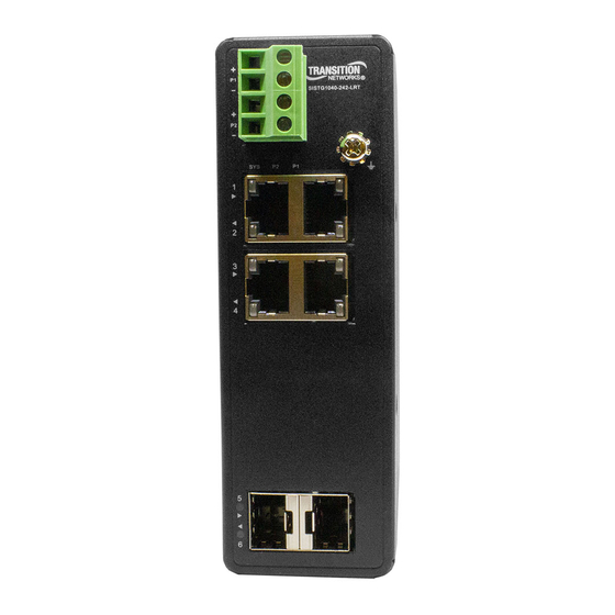
3. Review the front panel description the Install Guide. Use the front panel grounding screw as required; see chapter 3
of the Install Guide.
4. Install SFP modules. Refer to the specific SFP manual for cautions and warnings. Note: The SFP ports should use UL
Listed Optional Transceiver product, Rated 3.3Vdc, Laser Class 1.
5. Connect to Network / Devices: the switches provide eight or four 10M/100M/1G RJ45 ports. Use Cat 5e or better
unshielded twisted pair (UTP) cable terminated with an RJ-45 connector.
6. Connect to +12 to +48VDC or -12 to -48VDC Power. Caution: Before applying power from an AC outlet, insert
terminal connectors into the SISTG1040-2x2-LRT switch and verify all connections. Plugging in power connection
after energizing power supply(s) may damage the switch. a) Connect the wires between the +P1 and –P1 terminals
on the switch terminal block and the +V and -V terminals on the power supply. Optionally, connect the wires
between the +P2 and –P2 terminals on the switch terminal block and the +V and -V terminals on the power supply if
redundant power is to be used.
b) Use a small Phillips screwdriver to tighten the wire-clamp screws. c) Connect the three wires (e.g., green, black,
white) of the power cord to the Ground (
screwdriver to tighten the wire-clamp screws. d) Connect the plug end of the power cord into a live AC outlet.
e) Verify that the Power Supply front panel DC OK LED is lit. See the Install Guide for more details.
7. Check the SYS LED. If it is lit, the power connection is correct. If not, see the Install Guide.
These devices are open-type devices that are to be installed in an enclosure only accessible with the use of a tool, suitable for the
environment. This equipment is suitable for use in Class I, Division 2, Groups A, B, C, and D or non-hazardous locations only.
"WARNING – EXPLOSION HAZARD. DO NOT DISCONNECT WHILE THE CIRCUIT IS LIVE OR UNLESS THE AREA IS FREE OF IGNITIBLE
CONCENTRATIONS. Temperature code (T-Code) – T4.
33734 Rev. C
- Installation et fonctionnement corrects (français): Ces périphériques sont des périphériques de type ouvert qui
), N, and L clamp connections respectively. Use a small Phillips
https://www.transition.com
SISTG1040-2x2-LRT Quick Start Guide
Page 1 of 2
Advertisement
Table of Contents

Subscribe to Our Youtube Channel
Related Manuals for Transition Networks SISTG1040-2 2-LRT Series


Summary of Contents for Transition Networks SISTG1040-2 2-LRT Series
- Page 1 SISTG1040-2x2-LRT Quick Start Guide SISTG1040-2x2-LRT Quick Start Guide Introduction Transition Networks’ SISTG1040-242-LRT and SISTG1040--282-LRT are Industrial Unmanaged GbE Switches suitable for industrial Ethernet applications. See the SISTG1040-2x2-LRT Install Guide for important Cautions, Warnings, Features, Specifications, Front & Back Panel, LEDs, RESET button, Installation, Package Contents, and Troubleshooting, Warranty, Support &...
- Page 2 Data Sheets, etc. go to the Support Library (no logon required). Transition Networks | 10900 Red Circle Drive | Minnetonka, MN 55343, U.S.A. Technical Support: available 24-hours a day. US and Canada: 1-800-260-1312; International: 00-1-952-941-7600. | tel: +1.952.941.7600 | toll free: 1.800.526.9267 | fax: 952.941.2322 |...
Need help?
Do you have a question about the SISTG1040-2 2-LRT Series and is the answer not in the manual?
Questions and answers