
Subscribe to Our Youtube Channel
Related Manuals for Kramer TP-185


Summary of Contents for Kramer TP-185
- Page 1 Kramer Electronics, Ltd. USER MANUAL Model: TP-185 8 Channel UXGA/Audio/RS-232 to CAT 5 Transmitter...
-
Page 2: Table Of Contents
Kramer Communication Protocol 2000 Figures Figure 1: TP-185 Front and Rear Panels Figure 2: Connecting the TP-185, 8 Channel UXGA/Audio/RS-232 to CAT 5 Transmitter 7 Figure 3: Connecting Multiple TP-185 Units via RS-485 Figure 4: TP-185 DIP-switch RS-485 Termination Figure 5: TP-185 Reply Enable and Disable DIP-switch... - Page 3 Contents Tables Table 1: TP-185 Front and Rear Panel Features Table 2: Hardware Mode Reply Source DIP-switch Setting Table 3: Software Mode RS-485 Machine Number DIP-switch Setting Table 4: Serial Port Baud Rate DIP-switch Setting Table 5: UTP Connector Pinout...
-
Page 4: Introduction
Introduction Introduction Welcome to Kramer Electronics! Since 1981, Kramer Electronics has been providing a world of unique, creative, and affordable solutions to the vast range of problems that confront the video, audio, presentation, and broadcasting professional on a daily basis. In recent years, we have redesigned and upgraded most of our line, making the... -
Page 5: Quick Start
Getting Started 2.1 Quick Start This quick start chart summarizes the basic setup and operation steps. KRAMER: SIMPLE CREATIVE TECHNOLOGY... -
Page 6: Overview
RS-232 signals. The CAT 5 outputs can be connected to any Kramer compatible TP receiver, for example, the TP-126. The TP-185 can also route data from the RS-232 or RS-485 port to any of the CAT 5 outputs. -
Page 7: Defining The Tp-185 8 Channel Uxga/Audio/Rs-232 To Cat 5 Transmitter
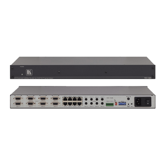
Defining the TP-185 8 Channel UXGA/Audio/RS-232 to CAT 5 Transmitter Figure 1 Table 1 define the front and rear panels of the TP-185, 8 Channel UXGA/Audio/RS-232 to CAT 5 Transmitter. Figure 1: TP-185 Front and Rear Panels KRAMER: SIMPLE CREATIVE TECHNOLOGY... -
Page 8: Table 1: Tp-185 Front And Rear Panel Features
Defining the TP-185 8 Channel UXGA/Audio/RS-232 to CAT 5 Transmitter Table 1: TP-185 Front and Rear Panel Features Feature Function POWER LED Lights green when the unit is turned on VIDEO INPUT 15-pin HD Connect to the VGA/UXGA video sources (from 1 to 8) -
Page 9: Installing The Tp-185 In A Rack
Installing the TP-185 in a Rack Installing the TP-185 in a Rack This section describes what to do before installing in a rack and how to rack mount the TP-185. KRAMER: SIMPLE CREATIVE TECHNOLOGY... -
Page 10: Connecting And Configuring The Tp-185
1 You do not need to connect all inputs and outputs 2 Switch off the power on each device before connecting it to your TP-185. After connecting your TP-185, switch on its power and then switch on the power on each device. DO NOT push in the rear panel Flash Program PROG button , it is only used for upgrading to the... -
Page 11: Connecting To The Tp-185 Via An Rs-232 Connection
6.2 Connecting to the TP-185 via an RS-232 Connection To connect the RS-232 port on the TP-185 to an RS-232 device: 1. Connect the RS-232 Tx pin on the TP-185 to pin 2 (9-pin D-sub) on the RS-232 device 2. Connect the RS-232 Rx pin on the TP-185 to pin 3 (9-pin D-sub) on the RS-232 device 3. -
Page 12: Connecting Multiple Tp-185 Units Via The Rs-485 Bus
Connecting and Configuring the TP-185 6.4 Connecting Multiple TP-185 Units via the RS-485 Bus You can connect up to 8 TP-185 units via the RS-485 bus with control from a PC or serial controller. To connect up to 8 TP-185 units via RS-485 (see Figure 1. -
Page 13: Setting The Dip-Switches On The Tp-185
• Baud rate • Hardware/software mode Moving a DIP-switch down turns the switch on, moving it up turns the switch off. Note: Changing any DIP-switch requires that you cycle power on the TP-185 7.1.1 Setting the RS-485 Bus Termination The DIP-switch sets the RS-485 bus termination. Only the first and last physical device on the RS-485 bus must be terminated, all other devices must be un-terminated. -
Page 14: Setting The Reply Source Or Machine Number
Reply is taken from output 7 OFF ON Reply is taken from output 8 Note: When there is more than one TP-185 attached to the RS-485 bus only one unit can have a reply path set. Table 3: Software Mode RS-485 Machine Number DIP-switch Setting... -
Page 15: Setting The Rs-232/Rs-485 Baud Rate Dip-Switches
7.1.5.1 Hardware Mode In Hardware mode, the: • RS-232 data is passed from any input to all outputs • TP-185 routes the reply from the output port defined by the DIP-switches 2, 3 and 4 (see Section 7.1.2). For reliable operation, only one port can be defined... -
Page 16: Wiring The Twisted Pair Rj-45 Connectors
Wiring the Twisted Pair RJ-45 Connectors 7.1.5.2 Software Mode In Software mode, the TP-185 routes the data and reply based on the Protocol 2000 commands received from the PC or other device connected to any of the inputs. The following example illustrates a typical command sequence. The destination and return paths to and from the end-user device are set (TP-185 control commands), then an end-user device command is sent to the defined destination. -
Page 17: Technical Specifications
Technical Specifications Technical Specifications Technical specifications of the TP-185 are shown in Table Table 6: Technical Specifications of the TP-185 INPUTS: 8 UXGA on 15-pin HD connectors (VGA through WUXGA) 8 unbalanced stereo audio 3.5mm mini jacks OUTPUTS: 8 TP on RJ-45 connectors... -
Page 18: Kramer Communication Protocol 2000
Default Communication Parameters 10.1 Kramer Communication Protocol 2000 The RS-232/RS-485 Protocol 2000 uses four bytes of information as shown in Table 8. The data rate is set by the DIP-switches (see Table 4), with no parity, 8 data bits and 1 stop bit. -
Page 19: Table 9: Instruction Codes For The Tp-185
Default Communication Parameters Table 9: Instruction Codes for the TP-185 INSTRUCTION DEFINITION FOR SPECIFIC INSTRUCTION NOTE DESCRIPTION INPUT OUTPUT CONTROLS THE STATUS OF A PORT 0–close Output bit: 1, 2, 4, 5 O0–O5 = output # or 0 for all outputs 1–open... - Page 21 For the latest information on our products and a list of Kramer distributors visit www.kramerelectronics.com where updates to this user manual may be found. We welcome your questions, comments, and feedback. Safety Warning: Disconnect the unit from the power supply before opening/servicing.
Need help?
Do you have a question about the TP-185 and is the answer not in the manual?
Questions and answers