Table of Contents
Advertisement
Advertisement
Table of Contents

Related Manuals for Waldorf Pulse


Summary of Contents for Waldorf Pulse
- Page 1 S Y N T H E S I Z E R User’s Manual Pulse • Pulse Plus...
- Page 3 Produktgarantie / Product Warranty Vielen Dank für den Kauf dieses Waldorf Produktes. Es zeichnet sich durch Thank you for choosing this Waldorf product. It is a dependable device and Zuverlässigkeit und Langlebigkeit aus. Dennoch können Material- oder is designed to last. However, the potential for defects in material or Verarbeitungsfehler nicht völlig ausgeschlossen werden.
- Page 4 Produktunterstützung / Product Support Wenn Sie Fragen zu Ihrem Waldorf Produkt haben, gibt es vier If you have any questions about your Waldorf product, feel free to contact us Möglichkeiten, uns zu kontaktieren: via one of the four options listed below.
-
Page 5: Table Of Contents
Influencing Sounds via Control Change Messages ....39 Controller as Modulation Sources ......39 User’s Manual Pulse • PulsePlus... - Page 6 The Hold Mode ......... 45 Additional Functions of the Pulse Plus ......46 11.1...
-
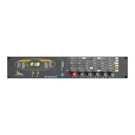
Page 7: Control Features And Connections
Power supply socket DC 12V MIDI Thru jack Stereo Out Right MIDI Out jack Stereo Out Left/Mono The additional connectors of the Pulse Plus are described in the chapter „Additional Functions of the Pulse Plus“. User’s Manual Pulse • PulsePlus... -
Page 8: Foreword
Düren, Drew Neumann, Geoff Farr, Siggi, Bonni, Hubi, Philipp, Rainer und Martin. Waldorf Electronics is not liable if this manual contains erroneous information. The contents of this manual may be updated at any time without prior notice. We made every effort to ensure the information herein is accurate and that the manual contains no contradictory information. -
Page 9: Introduction
4. Introduction This handbook was written to help you become familiar with the Waldorf Pulse. It will also help experienced users with routine tasks. To avoid confusion, the terminology in this manual is based on the Pulse parameter names. You will find a glossary at the end of the manual; it explains the various terms used herein. -
Page 10: General Safety Guidelines
5.4 Maintenance • Do not open the device or remove the cover. Refer all service and repair tasks to qualified personnel. The interior of the chassis contains no components that require user maintenance. User’s Manual Pulse • PulsePlus... -
Page 11: Proper Use
This device is designed exclusively to produce low-frequency audio signals for the purpose of generating sound. Any other use is prohibited and voids the warranty extended by Waldorf Electronics. Waldorf Electronics is not liable for damages due to incorrect use. User’s Manual Pulse • PulsePlus... -
Page 12: Setup And Operation
Pulse takes up 89 mm, equivalent to two rack spaces. 6.3 Connections In order to get started with your Pulse you will need an AC wall socket, a MIDI keyboard, a mixing console, an amp and an audio monitor such as a speaker cabinet. - Page 13 Stereo Out Right to your mixing console. If you do not choose to connect a mixing console, you can patch the Pulse's output signals directly to an amp. Use an input usually called Aux or Tape input. If you do not want to send a stereo signal, use Stereo Out Left/Mono output.
-
Page 14: Operation
First, the version number of the Pulse's operating software will in appear the display Version number of the operating software Example: 1.25 After several seconds, a program number will appear in the display; the Pulse is now ready to be played. 7.2 Selecting Programs Factory and User Programs The Waldorf Pulse features 99 sound programs which are also called memory locations. -
Page 15: Random Program
Random program When the Pulse switches off, its memory stores the last active program and reactivates this program when the Pulse switches back on. However, any edits you did not save are lost when the Pulse switches off. 7.3 Editing Sound Parameters In order to change or edit a sound in the Pulse, you must access the appropriate parameters. - Page 16 The letter E. will appear in front of the progam number in the display. Example: Program 27 in Edit mode The Pulse is equipped with a feature called an edit buffer. It enables you to activate other programs without deleting the changes you made to the current program. However, as soon as you begin editing another program, the modifications you made to the previous program are lost.
-
Page 17: The Store Function
The indicated memory location number will always be from 1 to 40, i.e. within the range of the freely programmable memory locations. If you have edited a factory preset program, it must be stored in one of these memory locations. The Pulse will suggest a program number equivalent to the original number plus 40. -
Page 18: The Compare Function
The value does not change when you turn the rotary pot. • Release the Mode key If the currently active program is in Compare status, the original parameter value will appear in the display when you turn the pot. User’s Manual Pulse • PulsePlus... -
Page 19: Sound Parameters
Control signal Pulse Plus only Diagram 4: Block schematic diagram for the Pulse As you can see, the Pulse consists of two different types of components for sound generation and sound shaping: • Oscillators, mixer, filter, VCA. Sound generation actually occurs within the oscillators. They produce square, sawtooth and triangular waveshapes. -
Page 20: Oscillators
PW stands for pulsewidth. If you select a square waveshape, you can determine its pulsewidth. The value 0 is equivalent to a pulse ratio of 1%, the value 127 is equivalent to 50%. -
Page 21: Oscillator 2
Crossmodulation is a XOR combination of the square waveshapes of Oscillators 2 and 3: Oscillator 2 Oscillator 3 Crossmodulation Diagram 6: Crossmodulation It produces a waveshape that contains the sum of as well as the difference between the two original waveshapes. User’s Manual Pulse • PulsePlus... -
Page 22: Diagram 7: Oscillator Synchronisation
Additionally, you can switch synchronization on and off independently. 0...127 Determines the pulsewidth of the square wave. If you select a waveshape other than pulse, than this parameter has no influence on that waveshape. Sync Switches synchronization with Oscillator 3 on and off. -
Page 23: Oscillator 3
The following waveshapes are available: Pulse: square Sawtooth Triangle Noise Generator In addition to the oscillators, a noise generator that produces pink noise is available. The noise generator has just one parameter: volume. Volume is determined via the mixer. User’s Manual Pulse • PulsePlus... -
Page 24: Mixer
Volume of the external audio signal External The mixer's output sends the signal to the filter's input. The Pulse is designed to enable you to overdrive this signal. Saturation occurs at the following values: • If you program a sound using just one oscillator, then the signal is overdriven somewhere in the volume value range of 40. -
Page 25: Low-Frequency Oscillators (Lfos)
LFO1 Speed / Shape LFO2 Speed / Delay In addition to the main oscillators, the Pulse is equipped with two low-frequency oscillators which are also used for modulation purposes. The acronym "LFO" has become the standard term for low-frequency oscillators. - Page 26 Keytrack and Pitch Follow to change the pitch of the current note via the LFO, just as you would for an oscillator. For the waveshapes triangle, sawtooth and pulse there is an additional MIDI Sync Mode, which is used to synchronise the LFO speed to MIDI Clock.
-
Page 27: Lfo 2
1 Trigger Mode; in other words, the trigger mode of the filter envelope. In the two Single Trigger modes, LFO 2 oscillation is not delayed at all when you play legato notes. Use this effect for typical keyboard solos. User’s Manual Pulse • PulsePlus... -
Page 28: Envelopes
8.5 Envelopes The Pulse's envelopes allow you to manipulate the sound parameters via rate or timed modulations. These envelopes feature ADSR characteristics. Most analog synthesizers feature ADSR envelopes. These envelopes are made up of four parameters that determine their response: Attack, Decay, Sustain and Release. -
Page 29: Envelope 2
Envelope 2 The second envelope is designed to control the volume (VCA), but can also used for other modulations. Its parameters are identical to those of Envelope 1. User’s Manual Pulse • PulsePlus... -
Page 30: Modulations
If both values are negative, then the modulation is positive just as the product of two negative numbers is positive when they are multiplied. The Pulse features different types of modulations: • Four modulation chains with freely assignable sources, amounts and destinations. - Page 31 7 Osc 2 Level 8 Osc 3 Level 9 Noise Level 10 Cutoff 11 Resonance 12 Volume 13 Panning 14 LFO 1 Speed 15 Mod 1 Amount Table 3: Modulation destinations Here are some examples of modulation assignments: User’s Manual Pulse • PulsePlus...
- Page 32 Alters the pitch of or positive Amount Oscillator 2, especially interesting with sync or crossmodulation sounds Panning Position of the sound within stereo panorama is determined by the MIDI notes. Table 4: Examples of modulation assignments User’s Manual Pulse • PulsePlus...
- Page 33 Breath Controller. 15 Control X Resonance Changes the filter resonance. * Unless stated otherwise, these examples apply to a positive value for "Amount" (01...63). Table 4: Examples of modulation assignments (continued) User’s Manual Pulse • PulsePlus...
-
Page 34: Routing A Modulation Source To Cv 2 Out
Routing a Modulation Source to CV 2 Out On the Pulse Plus, one of the 16 modulation sources can be routed to the CV 2 Out jack with variable amount. In this case, the control voltage is treated as a kind of destination in the modulation matrix. -
Page 35: Pitch Modulation
MIDI Pitchbend messages and are usually called pitch wheels or pitch benders. In the Pulse, Pitchbend messages can be used to modulate the pitch for all oscillators. 0...24 Determines the intensity of the pitchbend in semitones Pitchbend Scale via the Pitchbend messages. -
Page 36: Filter
Resonance Once the audio signal leaves the mixer, it is sent to a variable analog low-pass filter. This filter is a component that has significant influence on the Waldorf Pulse's sound characteristics. A low-pass filter dampens frequencies that lie above a defined cutoff frequency. -
Page 37: Vca
Volume / Velo Sens Panning The final component in the Pulse's signal chain is the VCA (voltage-controlled amplifier) The VCA determines master volume and the stereo position. The signal is then sent to the two outputs, where you can patch it to other devices. -
Page 38: Global Parameters
Global parameters are stored automatically when you modify them, so you are not required to save them separately. The Pulse Plus has an extended set of global parameters, requiring a different setting procedure. Please read the chapter „Additional Functions of the Pulse Plus“, which contains an overwiew of all global parameters and the setting procedure. -
Page 39: Midi Control
9.1 Calling Programs via Program Change All of the Pulse's sound programs can be called via MIDI Program Change messages. As the device contains 100 program locations, it recognizes program numbers 1...100. Program number 100 is a random program. -
Page 40: Aftertouch As A Modulation Source
The dump may take a few seconds. The Pulse cannot be played during this time. Receiving System Exclusive Data You are not required to activate a special receive mode at the Pulse in order to receive system exclusive data via MIDI. The transmission is activated via a Dump Request command originating at the device that is sending the messages. -
Page 41: Controller Dump
• Check out the parameter Device ID. Data transmission will only be executed successfully if the receiver and sender setting coincide. • Make sure none of the Pulse's programs are in Edit mode. All edits that were not stored prior to the dump will be irretrievably lost! •... -
Page 42: The Arpeggiator
An arpeggiator is a device that breaks an incoming MIDI chord down into single notes and plays them rhythmically. Different sequence modes can be defined for the arpeggiator. In addition to the synthesis features, the Pulse is equipped with an arpeggiator. It can be programmed and stored individually for every sound program. -
Page 43: Diagram 9: Arpeggiator Patterns
Here is an overview of the Arpeggiator patterns: Diagram 9: Arpeggiator patterns Pattern r15 is a shuffle groove with a swing factor of 58%. User’s Manual Pulse • PulsePlus... - Page 44 Assign Mode down: As described above, however notes are played in downwards direction. Assign Mode alternate: As described above, however notes are played alternately up and down. User’s Manual Pulse • PulsePlus...
-
Page 45: Arpeggiator Synchronization Via Midi Clock
10.1 Arpeggiator Synchronization via MIDI Clock The Pulse's Arpeggiator can be used as a master as well as a slave via the MIDI Clock: • When you use the Arpeggiator as the master, set its speed via the "Tempo" parameter. The "Global MIDI Channel" parameter must then be set to a value within the range of A.01...A.16 or A.on. -
Page 46: Additional Functions Of The Pulse Plus
The extension consists of: • An audio input for feeding in external signals • A CV/Gate interface for connecting analog synthesizers 11.1 Connections The following additional jacks are located on the rear panel of the Pulse Plus. CV / GATE FILTER CV In... -
Page 47: Cv/Gate Interface
MIDI data. The notes generated on this way can be used to trigger the sound generation of the Pulse. Also they can be sent out at the MIDI Out jack for recording and postprocessing. -
Page 48: Global Parameters
11.4 Global Parameters Setting According to the extended number of global parameters on the Pulse Plus, a different setting procedure is required. This is how you make changes to the global parameters: • Press the Mode key repeatedly until the LED next to parameter group GLB (Line 4) illuminates. -
Page 49: Cv/Gate Parameters
MIDI send and receive channel for the CV/Gate interface Off, 1...16 Example: Channel 3 When this parameter is set to Off, the Pulse sends out the played notes via CV and Gate Out . An incoming control voltage at CV In and Gate 1 Out triggers the sound generation of the Pulse. - Page 50 Determines the active polarity of the Gate In input. positive (high level): negative (low level): Gate Out Polarity Determines the active level and polarity of the Gate Out output. 5V, active low: 12V, active low: 5V, active high: 12V, active high: User’s Manual Pulse • PulsePlus...
- Page 51 -64...+63 To proceed the adjustment, connect the CV Out 1 output of the Pulse to the CV input of the synthesizer. Connect the Gate jacks in the same way. What to do next depends on the scaling method of the output signal, which is controlled by the parameter CV Out Curve: •...
-
Page 52: Stacking Two Or More Pulses
" 1 of 1 ". This means "I am Pulse #1 of a stack of #1 Pulses". This is the same as one monophonic Pulse. • Use the both leftmost rotary pots to alter these values. In case you have three... - Page 53 • If you do not use a computer or you have no more MIDI input, simply connect MIDI in of the second Pulse to MIDI out of the first one instead of MIDI thru. The received Notes, Pitch-Bend messages and Controller data are also sent to MIDI out of the first Pulse.
-
Page 54: Tips And Tricks
13. Tips and Tricks Here are a few tips that will help you make the most of your Pulse. • The lower the input signal, the greater the effect the filter has on the overall sound. If you want a heavily filtered sound, set the oscillators' volume parameters to low values in the mixer. -
Page 55: Trouble-Shooting
14. Trouble-Shooting If you run into any problems with your Pulse, please consult the checklist below. Many perceived errors are just minor oversights that can be corrected quickly. If you still can't solve the problem, please contact a qualified repair center or Waldorf Product Support. The address and telephone number are printed on the warranty card. -
Page 56: Tuning The Filter
The filter is tuned at the factory prior to shipping and, as a rule, is very stable. However, the Pulse is an actual analog synthesizer, so diverse factors may cause slight tuning problems. Therefore we recommend that you re-calibrate it from time to time. On demand, the Pulse executes this function automatically. -
Page 57: Appendix
Input impedance: 1MOhm CV Input Max. input level: 0...+5V Input impedance: 1MOhm Gate Input Input level: 0...+12V Input impedance: 100kOhm CV Output Output level: -0,5...+5,5V Output impedance: 250Ohm Gate Output Output level: 0...+11V Output impedance: 250Ohm User’s Manual Pulse • PulsePlus... -
Page 58: (B) Midi Controller Assignments
-64...+63 0...3 Env1 Trigger 0: Single-Trigger 1 1: Single-Trigger 2 2: Retrigger 1 3: Retrigger 2 0...127 Env2 Keytrack -64...+63 0...3 Env2 Trigger 0: Single-Trigger 1 1: Single-Trigger 2 2: Retrigger 1 3: Retrigger 2 User’s Manual Pulse • PulsePlus... - Page 59 Cutoff Keytrack -64...+63 0...127 Cutoff Env1 Sens -64...+63 0...127 Cutoff Velo Sens -64...+63 0...15 Cutoff Mod Source see Table 0...127 Cutoff Mod Amount -64...63 0...127 Resonance 0...127 0...127 Volume 0...127 0...127 Volume Velo Sens -64...+63 User’s Manual Pulse • PulsePlus...
- Page 60 Mod Unit 3 Amount -64...+63 0...15 Mod Unit 3 Destination see Table 0...15 Mod Unit 4 Source see Table 0...127 Mod Unit 4 Amount -64...+63 0...15 Mod Unit 4 Destination see Table Reset All Controls All Notes Off User’s Manual Pulse • PulsePlus...
-
Page 61: (C) System Exclusive Data Format
LFO1 Speed 0...127 0...7 LFO1 Shape 0: Sine 1: Triangle 2: Sawtooth 3: Pulse 4: Sample & Hold 5: Triangle Sync 6: Sawtooth Sync 7: Pulse Sync 0...127 LFO2 Speed 0...127 0...127 LFO2 Delay 0...127 User’s Manual Pulse • PulsePlus... - Page 62 Table 0...127 Mod Unit 3 Amount -64...+63 0...15 Mod Unit 3 Destination see Table 0...15 Mod Unit 4 Source see Table 0...127 Mod Unit 4 Amount -64...+63 0...15 Mod Unit 4 Destination see Table User’s Manual Pulse • PulsePlus...
- Page 63 -64...+63 0...127 Panning L64...R63 0...127 External Signal Level 0...127 0...15 CV 2 Source see Table 0...127 CV 2 Amount -64...+63 reserved Checksum Checksum via bytes 6 through 74, bit 7 cleared End of SysEx message User’s Manual Pulse • PulsePlus...
- Page 64 LFO1 Speed 0...127 0...7 LFO1 Shape 0: Sine 1: Triangle 2: Sawtooth 3: Pulse 4: Sample & Hold 5: Triangle Sync 6: Sawtooth Sync 7: Pulse Sync 0...127 LFO2 Speed 0...127 0...127 LFO2 Delay 0...127 User’s Manual Pulse • PulsePlus...
- Page 65 Table 0...127 Mod Unit 3 Amount -64...+63 0...15 Mod Unit 3 Destination see Table 0...15 Mod Unit 4 Source see Table 0...127 Mod Unit 4 Amount -64...+63 0...15 Mod Unit 4 Destination see Table User’s Manual Pulse • PulsePlus...
- Page 66 -64...+63 0...127 Panning L64...R63 0...127 External Signal Level 0...127 0...15 CV 2 Source see Table 0...127 CV 2 Amount -64...+63 reserved Checksum Checksum via bytes 6 through 74, bit 7 cleared End of SysEx message User’s Manual Pulse • PulsePlus...
- Page 67 3: 12H 0...1 CV Out Curve 0: logarithmic 1: linear 0...127 CV Out Adjust -64...+63 0...127 CV Out Offset -64...+63 reserved Checksum Checksum via bytes 5 through 14, bit 7 cleared End of SysEx message User’s Manual Pulse • PulsePlus...
- Page 68 Function Code Dump type, polyphony parameter dump 0...11 Number of Pulses Total number of Pulses-1 in stack 0...11 Identification Number Identification number of Pulse-1 in stack End of SysEx message Program Dump Request Byte No Value Parameter Description/Range Exclusive Status...
- Page 69 Exclusive Status SysEx transfer start Manufacturer ID Waldorf Electronics GmbH Model ID Pulse ID 0...126 Device ID Equivalent to the global parameter device ID Function Code Dump type polyphony parameter dump request End of SysEx message User’s Manual Pulse • PulsePlus...
-
Page 70: Glossary
The filter cutoff frequency is a significant factor for filters. A low-pass filter dampens the portion of the signal that lies above this frequency. Frequencies below this value are allowed to pass through without being processed. User’s Manual Pulse • PulsePlus... - Page 71 Essentially, this is how MIDI works: One sender is connected to one or several receivers. For instance, if you want to use a computer to play the Pulse, then the computer is the sender and the Pulse acts as the receiver. With a few exceptions, the majority of MIDI devices are equipped with two or three ports for this purpose: MIDI In, MIDI Out and in some cases MIDI Thru.
- Page 72 Sustain An envelope parameter. The term "Sustain" describes the level of an envelope that remains constant after it has run through the Attack and Decay phases. Sustain lasts until the trigger is terminated. User’s Manual Pulse • PulsePlus...
- Page 73 LFO. VCF is the acronym for voltage-controlled filter. It is a filter component that allows you to manipulate the filter parameters via control voltages. Volume The term describes a sound's output level. User’s Manual Pulse • PulsePlus...
-
Page 74: Midi Implementation Chart
*** See Chapter 8 for Parameters Control X is assignable to 0-127 Mode 1: OMNI ON, POLY Mode 2: OMNI ON, MONO o : Yes Mode 3: OMNI OFF, POLY Mode 4: OMNI OFF, MONO x : No User’s Manual Pulse • PulsePlus... -
Page 75: Declaration Of Conformity
Declaration of Conformity Für das folgend bezeichnete Erzeugnis For the following named product Waldorf Pulse wird hiermit bestätigt, daß es den Schutzanforderungen entspricht, die in der Richtlinie 89/336/FWG des Rates zur Angleichung der Rechtsvorschriften der Mitgliedstaaten über die elektromagnetische Verträglichkeit festgelegt sind; außerdem entspricht es den Vorschriften des Gesetzes über die elektromagnetische Verträglichkeit von Geräten (EMVG) vom 30. - Page 76 1. IMPORTANT NOTICE: DO NOT MODIFY THIS UNIT! This product, when installed as indicated in the instructions contained in this Manual, meets FCC requirements. Modifications not expressly approved by Waldorf may void your authority, granted by the FCC, to use this product.
- Page 78 S Y N T H E S I Z E R © Waldorf Electronics 1997 • Printed in Germany Waldorf Electronics GmbH • Neustraße 12 • D-53498 Waldorf • Germany • http://www.waldorf-gmbh.de...
Need help?
Do you have a question about the Pulse and is the answer not in the manual?
Questions and answers