Sign In
Upload
Download
Table of Contents
Contents
Add to my manuals
Delete from my manuals
Share
URL of this page:
HTML Link:
Bookmark this page
Add
Manual will be automatically added to "My Manuals"
Print this page
×
Bookmark added
×
Added to my manuals
Manuals
Brands
Waldorf Manuals
Synthesizer
MicroWave II
User manual
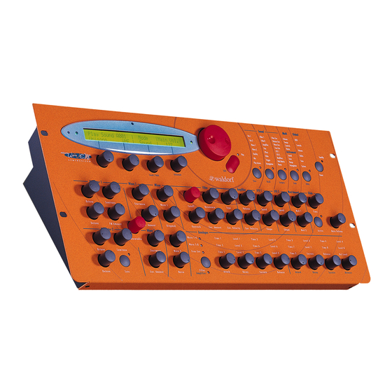
Waldorf MicroWave II User Manual
Synthesizers
Hide thumbs
1
2
3
4
Table Of Contents
5
6
7
8
9
10
11
12
13
14
15
16
17
18
19
20
21
22
23
24
25
26
27
28
29
30
31
32
33
34
35
36
37
38
39
40
41
42
43
44
45
46
47
48
49
50
51
52
53
54
55
56
57
58
59
60
61
62
63
64
65
66
67
68
69
70
71
72
73
74
75
76
77
78
79
80
81
82
83
84
85
86
87
88
89
90
91
92
93
94
95
96
97
98
99
100
101
102
103
104
105
106
107
108
109
110
111
112
113
114
115
116
117
118
119
120
121
122
123
124
125
126
page
of
126
Go
/
126
Contents
Table of Contents
Bookmarks
Table of Contents
Table of Contents
Control Features and Connections of the Microwave II
Additional Controls and Connectors of the Microwave XT
Additional Controls and Connectors of the Xtk
Foreword
About this Manual
Symbols
Highlighted Control Features and Parameters
General Safety Guidelines
Proper Use
Setup and Operation
Inventory
Setup
Connections
Diagram 1: Connections
Analog Input
Quick Start
Operation
Power Switching
Powering up
Switching off
Adjusting the Master Volume
Selecting Programs
Selecting Sound and Multi Mode
Editing Parameters
Diagram 2: Parameter Pages
Edit Buffers
The Compare Function
Recalling Edits
Storing Programs
The Play Access Page
Panic Function
Randomizing a Program
Initializing Programs
Editing Parameters on the Microwave XT
Switching the Octave Setting on the Xtk
About Wavetable Synthesis
Sound Parameters
Overview of Functions
Diagram 3: Block Schematic Diagram for Single Sounds
Oscillators
Oscillator 1
Oscillator 2
Waves
Wave 1
Table 1: Wavetable Overview
Wave 2
Quality
Mixer
Play Access
Table 2: Play Access Abbreviations
Filter
Filter 1
Filter Types
Filter 2
Volume and Pan
Volume
Pan
Effects
Portamento and Glissando
Trigger
Arpeggiator
Diagram 4: Arpeggiator Patterns
Envelopes
Filter Envelope
Amplifier Envelope
Wave Envelope
Free Envelope
Low-Frequency Oscillators (Lfos)
Lfo 2
Lfo1
Modifiers and Modulation Matrix
Modifier Delay
Table 3: Modulation Sources
Modifier Units
Table 4: Modifier Functions
Modulation Matrix
Program Name
Table 5: Modulation Destinations
Multi Mode
Multi Parameters
Instrument Parameters
Selecting an Instrument for Editing
Sound
Tune
Range
Arpeggiator
Global Parameters
MIDI Control
Selecting Programs
Calling Programs Via Program Change
Influencing Sounds Via MIDI Messages
Controllers as Modulation Sources
Changing Sound Parameters Via Controllers
Pitchbending
Aftertouch and Poly Pressure
System Exclusive Data
System Exclusive Data Transmission
Sending System Exclusive Data
Receiving System Exclusive Data
Other Functions
Updating the System Software
Converting Microwave Sounds
Appendix
Technical Data
MIDI Controller Assignments
System Exclusive Data Format
Glossary
MIDI Implementation Chart
Advertisement
Quick Links
1
Control Features and Connections of the Microwave II
2
Technical Data
3
MIDI Controller Assignments
Download this manual
Bedienungsanleitung
User's Manual
Table of
Contents
Previous
Page
Next
Page
1
2
3
4
5
Advertisement
Table of Contents
Need help?
Do you have a question about the MicroWave II and is the answer not in the manual?
Ask a question
Questions and answers
Related Manuals for Waldorf MicroWave II
Synthesizer Waldorf IRIDIUM Quick Start Manual
(35 pages)
Synthesizer Waldorf IRIDIUM User Manual
(215 pages)
Synthesizer Waldorf QUANTUM User Manual
(231 pages)
Synthesizer Waldorf IRIDIUM CORE Quick Start Manual
(18 pages)
Synthesizer Waldorf MicroWave XT User Manual
Synthesizers (126 pages)
Synthesizer Waldorf BLOFELD User Manual
(117 pages)
Synthesizer Waldorf Blofeld User Manual
Desktop & keyboard (128 pages)
Synthesizer Waldorf streichfett User Manual
(31 pages)
Synthesizer Waldorf Attack Operation Manual
Percussion synthesizer (37 pages)
Synthesizer Waldorf rocket User Manual
(45 pages)
Synthesizer Waldorf Pulse User Manual
(78 pages)
Synthesizer Waldorf Q Synthesizer User Manual
Waldorf synthesizer (171 pages)
Synthesizer Waldorf zarenbourg Manual
Synthesizers (22 pages)
Synthesizer Waldorf KYRA User Manual
Va synthesizer (165 pages)
Synthesizer Waldorf M User Manual
Wavetable synthesizer (91 pages)
Synthesizer Waldorf largo User Manual
(99 pages)
This manual is also suitable for:
Microwave xt
Xtk
Table of Contents
Print
Rename the bookmark
Delete bookmark?
Delete from my manuals?
Login
Sign In
OR
Sign in with Facebook
Sign in with Google
Upload manual
Upload from disk
Upload from URL


Need help?
Do you have a question about the MicroWave II and is the answer not in the manual?
Questions and answers