Table of Contents
Advertisement
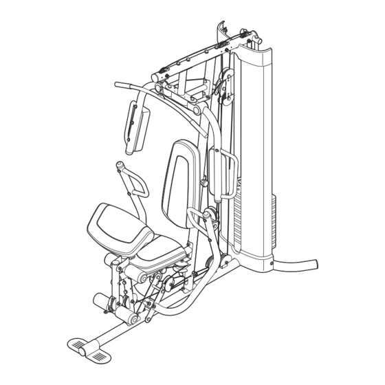
Model No. GGSY3058.0
Serial No.
Write the serial number in the
space above for future reference.
Serial Number Decal (under seat)
QUESTIONS?
As a manufacturer, we are com-
mitted to providing complete cus-
tomer satisfaction. If you have
questions, or if parts are damaged
or missing, PLEASE DO NOT
CONTACT THE STORE; please
contact Customer Care.
IMPORTANT: You must note the
product model number and
serial number (see the drawing
above) before contacting us:
CALL TOLL-FREE:
1-877-776-4777
Mon.–Fri. 6 a.m.–6 p.m. MST
Sat. 8 a.m.–4 p.m. MST
ON THE WEB:
www.goldsgympowerflex.com
CAUTION
Read all precautions and instruc-
tions in this manual before using
this equipment. Save this manual
for future reference.
USER'S MANUAL
Advertisement
Table of Contents

Related Manuals for Gold's Gym Platinum GGSY3058.0


Summary of Contents for Gold's Gym Platinum GGSY3058.0
- Page 1 Model No. GGSY3058.0 Serial No. Write the serial number in the space above for future reference. Serial Number Decal (under seat) QUESTIONS? As a manufacturer, we are com- mitted to providing complete cus- tomer satisfaction. If you have questions, or if parts are damaged or missing, PLEASE DO NOT CONTACT THE STORE;...
-
Page 2: Table Of Contents
Apply the decal in the location shown. Note: The decals may not be shown at actual size. GOLD'S GYM is a registered trademark of Gold's Gym International, Inc. This product is manufactured and distributed under license from Gold's Gym International, Inc. -
Page 3: Important Precautions
IMPORTANT PRECAUTIONS WARNING: To reduce the risk of serious injury, read all important precautions and instructions in this manual and all warnings on the weight system before using the weight system. ICON assumes no responsibility for personal injury or property damage sustained by or through the use of this product. -
Page 4: Before You Begin
BEFORE YOU BEGIN Thank you for selecting the versatile GOLD’S GYM PLATINUM weight system. The weight system offers a selection of exercise stations designed to develop every major muscle group of the body. Whether your goal is to tone your body, build dramatic muscle size and strength, or improve your cardiovascular system, the weight system will help you to achieve the specific results you want. -
Page 5: Part Identification Chart
PART IDENTIFICATION CHART Refer to the drawings below to identify small parts used in assembly. The number in parentheses by each draw- ing is the key number of the part, from the PART LIST near the end of this manual. Note: Some small parts may have been preattached. - Page 6 M8 x 69mm Shoulder Bolt (87) M8 x 75mm Carriage Bolt (83) M10 x 65mm Bolt (85) M10 x 75mm Bolt (82) M8 x 80mm Bolt (100) M8 x 65mm Bolt (101) M10 x 65mm Button Bolt (106) M10 x 80mm Bolt (84) M6 x 65mm Button Screw (91) M10 x 82mm Button Screw (92) M10 x 60mm Bolt (79)
- Page 7 Backrest Adjustment Knob (53) Curl Adjustment Knob (58) Seat Adjustment Knob (52)
-
Page 8: Assembly
ASSEMBLY Make Assembly Easier Everything in this manual is designed to ensure that the weight system can be assembled suc- cessfully by almost anyone. By setting aside plenty of time, assembly will go smoothly. Before beginning assembly, carefully read the following information and instructions: •... -
Page 9: Frame Assembly
Frame Assembly Before beginning assembly, make sure that you understand the information in the box on page 8. See the PART IDENTIFICATION CHARTS on pages 5–7 for help identifying small parts. Insert four M8 x 75mm Carriage Bolts (83) up into the Base (1). - Page 10 4. Attach the Frame (9) to the Upright (2) with two M8 x 80mm Bolts (100), two M8 Washers (103), and two M8 Nylon Locknuts (78). Do not tighten the Nylon Locknuts yet. Attach the Frame (9) to the Front Leg (10) with two M8 x 65mm Bolts (101), two M8 Washers (103), and two M8 Nylon Locknuts (78).
- Page 11 7. Attach the Top Frame (4) to the Upright (2) with two M8 x 80mm Bolts (100), two M8 Washers (103), and two M8 Nylon Locknuts (78). Do not tighten the Nylon Locknuts yet. Attach the Weight Guides (18) to the Top Frame (4) with two M10 x 20mm Button Screws (96) and two M10 Washers (80).
-
Page 12: Arm Assembly
Arm Assembly 10. Attach the Butterfly Frame Brace (6) to the Upright (2) with two M8 x 80mm Bolts (100), two M8 Washers (103), and two M8 Nylon Locknuts (78). Do not tighten the Nylon Locknuts yet. 11. Apply a small amount of the included grease in the locations shown. - Page 13 12. Attach the Butterfly Frame (5) to the Top Frame (4) with two M8 x 80mm Bolts (100), two M8 Washers (103), and two M8 Nylon Locknuts (78). Do not tighten the Nylon Locknuts yet. Attach the Butterfly Frame (5) to the Butterfly Frame Brace (6) with an M10 x 75mm Button Screw (118).
- Page 14 15. Grease in the locations shown and attach the Right Butterfly Arm (26) to the Right Butterfly Bracket (29) with an M10 x 75mm Bolt (82) and an M10 Nylon Locknut (77). Press a Bolt Cap (44) onto the end of the Bolt. Do not overtighten the Bolt;...
-
Page 15: Cable Assembly
18. Apply grease in the locations shown and attach the Left and Right Press Arms (15, 16) to the Base (1) with an M10 x 110mm Bolt (93), an 89.5mm Spacer (59), and an M10 Nylon Locknut (77). Do not over tighten the Nylon Locknut; the Press Arms must pivot easily. - Page 16 21. Wrap the Butterfly Cable (50) under a 90mm Pulley (48). Attach the Pulley and two Half Guards (55) to the Double “U”-bracket (61) with an M10 x 45mm Bolt (86) and an M10 Nylon Locknut (77). Make sure that the Half Guards are oriented as shown.
- Page 17 24. Identify the Lat Cable (49). Route the Cable up through the Top Frame (4) and over a 90mm Pulley (48). Attach the Pulley inside the Top Frame with an M10 x 80mm Bolt (84), two M10 Washers (80), two 19mm Spacers (67), and an M10 Nylon Locknut (77).
- Page 18 27. Route the Lat Cable (49) up through the Top Frame (4) and wrap the Cable over a Thin Pulley (24). Pull the M10 x 80mm Bolt (84) out of the Top Frame until it is flush with the first Thin Pulley from step 24.
- Page 19 30. Identify the Leg Lever Cable (51). Route the Cable through the Leg Lever (12) and the Front Leg (10). Insert a 90mm Pulley (48) into the Leg Lever (12) from behind it as shown. Attach the 90mm Pulley with an M10 x 65mm Bolt (85), two M10 Washers (80), two 13mm Steel Spacers (109), and an M10 Nylon Locknut (77).
- Page 20 33. Wrap the Leg Lever Cable (51) over a 90mm Pulley (48). Attach the Pulley, a Cable Trap (56), and two Half Guards (55) to the second hole from the bottom of the Pulley Plates (60) with an M10 x 50mm Bolt (97) and an M10 Nylon Locknut (77).
- Page 21 36. Wrap the Leg Lever Cable (51) under a 90mm Pulley (48). Attach the Pulley to the Upright (2) with an M10 x 120mm Bolt (115), two Half Guards (55), an M10 Washer (80), and a Cable Trap (56). 37. Wrap the Leg Lever Cable (51) under a 90mm Pulley (48).
-
Page 22: Seat Assembly
39. Wrap the Leg Lever Cable (51) around a 90mm Pulley (48). Attach the Pulley to the Left Press Arm (15) with an M10 x 50mm Bolt (97), two Half Guards (55), an M10 Washer (80), and a Cable Trap (56). Make sure that the Cable Trap and the Half Guards are oriented as shown. - Page 23 42. Attach the Backrest (31) to the Backrest Frame (7) with two M6 x 20mm Screws (88), an M6 x 38mm Screw (89), and an M6 Washer (114). Insert the Backrest Frame (7) into the Upright (2) and tighten the Backrest Adjustment Knob (53) into the Upright.
- Page 24 45. Attach the Butterfly Cover (30) to the Butterfly Bracket (5) with four M4 x 12mm Self-tapping Screws (102). 46. Attach the Curl Pad (33) to the Curl Post (11) with two M6 x 20mm Screws (88). 47. Make sure that all parts have been properly tightened. The use of the remaining parts will be explained in ADJUSTMENT, beginning on the following page.
-
Page 25: Adjustment
ADJUSTMENT This section explains how to adjust the weight system. Refer to the accompanying exercise guide to see the cor- rect form for each exercise. Make sure that all parts are properly tightened each time the weight system is used. Replace any worn parts immediately. -
Page 26: Adjusting The Backrest
USING THE CURL PAD To use the Curl Pad (33), remove the indicated 50mm Round Inner Cap (39) and insert the Curl Post (11) into the Front Leg (10). Tighten the Curl Adjustment Knob (58) into the Front Leg. Make sure that the Adjustment Knob passes through a hole in the Curl Post. -
Page 27: Weight Resistance Chart
LOCKING THE LEG LEVER To lock or unlock the Leg Lever, remove the Lock Plate Pin (95) from the Lock Plate (14). Move the Lock Plate to either the position shown on the Front Leg (10) or the indicated hole in the Leg Lever (12). Insert the Lock Pin back through the Lock Plate. -
Page 28: Cable Diagram
CABLE DIAGRAM The diagram below shows the proper routing of the cables. The numbers show the proper route for that cable. Use the diagram to make sure that the cables, cable traps, and finger guards have been assembled correctly. If the cables are not assembled correctly, the weight system will not function properly and damage may occur. -
Page 29: Maintenance
MAINTENANCE Make sure that all parts are properly tightened each time the weight system is used. Replace any worn parts immediately. The weight system can be cleaned with a damp cloth and a mild, non-abrasive detergent. Do not use solvents. TIGHTENING THE CABLES Woven cable, the type of cable used on the weight system, can stretch slightly when it is first used. -
Page 30: Exercise Guidelines
EXERCISE GUIDELINES THE FOUR BASIC TYPES OF WORKOUTS Muscle Building To increase the size and strength of your muscles, push them close to their maximum capacity. Your mus- cles will continually adapt and grow as you progres- sively increase the intensity of your exercise. You can adjust the intensity level of an individual exercise in two ways: •... -
Page 31: Cooling Down
The repetitions in each set should be performed smoothly and without pausing. The exertion stage of each repetition should last about half as long as the return stage. Proper breathing is important. Exhale during the exertion stage of each repetition and inhale during the return stroke. -
Page 32: Part List
PART LIST—Model No. GGSY3058.0 Key No. Qty. Description Base Upright Stabilizer Top Frame Butterfly Frame Butterfly Frame Brace Backrest Frame Seat Frame Frame Front Leg Curl Post Leg Lever Pad Tube Lock Plate Left Press Arm Right Press Arm Press Arm Handle Weight Guide Weight Weight Selector... - Page 33 Key No. Qty. Description M8 x 65mm Bolt M4 x 12mm Self-tapping Screw M8 Washer M4 Washer M10 Large Washer M10 x 65mm Button Bolt M6 Nylon Locknut 21mm Steel Spacer 13mm Steel Spacer M4 x 16mm Self-tapping Screw 7mm Spacer M12 Nut Note: Specifications are subject to change without notice.
-
Page 34: Exploded Drawing
EXPLODED DRAWING A—Model No. GGSY3058.0 70 71 R0408A... - Page 35 EXPLODED DRAWING B—Model No. GGSY3058.0 R0408A...
-
Page 36: Ordering Replacement Parts
ORDERING REPLACEMENT PARTS To order replacement parts, please see the front cover of this manual. To help us assist you, be prepared to provide the following information when contacting us: • the model number and serial number of the product (see the front cover of this manual) •...
Need help?
Do you have a question about the Platinum GGSY3058.0 and is the answer not in the manual?
Questions and answers
how do i order missing parts