
Related Manuals for Comtrend Corporation CT-5361T


Summary of Contents for Comtrend Corporation CT-5361T
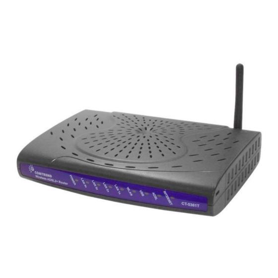
- Page 1 CT-5361T Wireless ADSL2+ Router User’s Manual Version A3.5, December 25, 2007 261056-038...
- Page 2 Copyright Copyright© 2007 Comtrend Corporation. All rights reserved. The information and messages contained herein are proprietary to Comtrend Corporation. No part of this document may be translated, transcribed, reproduced, in any form, or by any means without prior written permission by Comtrend Corporation.
-
Page 3: Table Of Contents
Table of Contents CHAPTER 1 INTRODUCTION ......................5 ..........................5 EATURES ..........................6 PPLICATION LED I ....................7 RONT ANEL NDICATORS CHAPTER 2 INSTALLATION ......................9 ......................9 ARDWARE NSTALLATION USB D ..............11 EVICE RIVER NSTALLATION USB D OS)..............14 RIVER ANUAL NSTALLATION CHAPTER 3 LOGIN VIA THE WEB BROWSER ..............19 IP A ..........................19 DDRESS... - Page 4 WAN............................56 LAN............................57 NAT ............................59 6.3.1 Virtual Servers ........................59 6.3.2 Port Triggering .......................61 6.3.3 DMZ Host ........................62 6.3.4 ALG ..........................63 ..........................64 ECURITY 6.4.1 IP Filtering ........................64 6.4.2 Parental Control ......................67 6.4.3 MAC Filtering.........................68 ......................70 UALITY OF ERVICE ..........................74 OUTING 6.6.1 Default Gateway ......................74 6.6.2 Static Route........................75 6.6.3...
- Page 5 9.1.3 Restore Default ......................107 .........................109 YSTEM TR-069 C ........................112 LIENT ........................114 NTERNET ......................... 115 CCESS ONTROL 9.5.1 Services......................... 116 9.5.2 Access IP Addresses...................... 117 9.5.3 Passwords ........................118 ........................ 119 PDATE SOFTWARE ........................120 AVE AND EBOOT APPENDIX A: FIREWALL ......................121 APPENDIX B: PIN ASSIGNMENTS....................127 APPENDIX C: SPECIFICATIONS....................128 APPENDIX D: SSH CLIENT ......................131...
-
Page 6: Chapter 1 Introduction
Chapter 1 Introduction The CT-5361T is an 802.11g (54Mbps) wired and Wireless Local Area Network (WLAN) ADSL router. Four 10/100 Base-T Ethernet ports and a single USB port provide wired LAN connectivity with an integrated 802.11g Wi-Fi WLAN Access Point (AP) for wireless connectivity. -
Page 7: Application
Application The following diagram depicts the application of the device on a wireless network. -
Page 8: Front Panel Led Indicators
Front Panel LED Indicators The front panel LED indicators are shown in the picture below and followed by an explanation in the table below. Color Mode Function Green The router is powered up. The router is powered down. POST (Power On Self Test) failure (not bootable) or Device malfunction. - Page 9 Green DSL good sync Modem power off Green Blink Flashing Green = DSL attempting sync ADSL Flashing at 2 Hz with a 50% duty cycle when trying to detect carrier signal Flashing at 4 Hz with a 50% duty cycle when the carrier has been detected and the modem is trying to train.
-
Page 10: Chapter 2 Installation
Chapter 2 Installation Hardware Installation In the rear panel, there is a reset button. To load the factory default settings, hold the reset button down for at least 5 seconds. Follow the instructions below to complete the hardware connections. Connection to LINE port If you wish to connect both the router and a telephone, connect the LINE port to a POTS splitter with a RJ11 connection cable. - Page 11 Connection to Power Connect the Power jack to the shipped power cord. Attach the power adapter to the wall outlet or other AC source. After all connections have been made, press the power-switch in to turn the device on. After power on, the router performs a self-test. Wait for a few seconds until the test is finished, then the router will be ready to operate.
-
Page 12: Usb Device Driver Auto-Run Installation
USB Device Driver Auto-run Installation Before you connect your router’s USB cable to your PC, you must load the ADSL USB drivers. The auto-run USB driver installation supports Win ME, Win 98, Win 2000, Win XP (32 bit) and Vista (32 bit). For those using Windows XP 64 bit, the driver needs to be installed manually (please see section 2.3 below for details), and the driver is also enclosed on the CD-ROM. - Page 13 STEP 3: When the screen displays as below, wait until the drivers are fully installed. STEP 4: Click the Finish button, when the screen displays as below.
- Page 14 STEP 5: Installation is complete.
-
Page 15: Usb Driver Manual Installation(64Bit Os)
USB Driver Manual Installation(64bit OS) Before you connect your router’s USB cable to your PC, you must load the ADSL USB drivers. This manual USB driver installation supports Windows XP 64 bit. To connect the router to a PC using the USB interface, you need to use a standard USB cable and install the USB interface software. - Page 16 Note: This screen won’t be displayed if the USB Driver has been previously un/installed. STEP 3: If you are installing the software from a disk, insert the disk. Note: When the auto-run screen pops up click Exit and continue with the manual installation process (see below).
- Page 17 STEP 4: Select the location of the file using the Browse button. Normally, the file is on the CD-ROM shipped with the device. STEP 5: Locate the Vista folder, and click the OK button.
- Page 18 STEP 6: When the screen displays as below, click the NEXT button.
- Page 19 STEP 7: Click the Finish button, when the screen displays as below. STEP 8: Installation is complete.
-
Page 20: Chapter 3 Login Via The Web Browser
IP Address The default IP address of the CT-5361T (LAN port) is 192.168.1.1. To configure the CT-5361T for the first time, the configuration PC must have a static IP address within the 192.168.1.x subnet. Follow the steps below to configure your PC IP address to use subnet 192.168.1.x. - Page 21 STEP 3: Click OK to submit the settings. STEP 4: Start your Internet browser and type the IP address for the router (192.168.1.1) in the Web address bar.
-
Page 22: Login Procedure
Perform the following steps to bring up the Web user interface and configure the CT-5361T. To log on to the system from the Web browser, follow the steps below: STEP 1: Start your Internet browser. Type the IP address for the router in the Web address field. - Page 23 Shown here is the Device Info screen for your reference.
-
Page 24: Default Settings
Default Settings During power on initialization, the CT-5361T initializes all configuration attributes to default values. It will then read the configuration profile from the Permanent Storage section on the flash memory. The default attributes are overridden when identical attributes with different values are configured. The configuration profile in Permanent Storage can be created via the Web user interface, telnet user interface, or other management protocols. -
Page 25: Chapter 4 Device Info
Chapter 4 Device Info After login, the Quick Setup screen appears as shown. Note: The selections available on the left side of menu are based upon the configured connection. -
Page 26: Wan
Click Device Info on the menu bar to display the WAN option. Then, click WAN on the Device Info menu bar to display the configured PVC(s) and the status. VPI/VCI Shows the values of the ATM VPI/VCI Con. ID Shows the connection ID Category Shows the ATM service classes Service... -
Page 27: Statistics
Statistics Selection of the Statistics screen provides statistics for the Network Interface of LAN, WAN, ATM and ADSL. All statistics screens are updated every 15 seconds. -
Page 28: Lan Statistics
4.2.1 LAN Statistics The Network Statistics screen shows the interface statistics for Ethernet, USB and Wireless interfaces. (The Network Statistics screen shows the interface statistics for the LAN interface. This provides byte transfer, packet transfer, Error and Drop statistics for the LAN interface.) -
Page 29: Wan Statistics
4.2.2 WAN Statistics Service Shows the service type VPI/VCI Shows the values of the ATM VPI/VCI Protocol Shows the connection type, such as PPPoE, PPPoA, etc. Interface Shows connection interfaces Received/Transmitted Bytes Number of Bytes Received/Transmitted Pkts Number of packets Received/Transmitted Errs Number of errored packets Received/Transmitted - Drops... -
Page 30: Atm Statistics
4.2.3 ATM statistics The following figure shows the ATM statistics screen. ATM Interface Statistics Field Description VPI/VCI Shows the values of the ATM VPI/VCI In Octets Number of received octets over the interface Out Octets Number of transmitted octets over the interface In Errors Number of cells dropped due to uncorrectable HEC errors In Unknown... - Page 31 In Idle Cells Number of idle cells received In Circuit Type Errors Number of cells received with an illegal circuit type In Oam RM CRC Errors Number of OAM and RM cells received with CRC errors In GFC Errors Number of cells received with a non-zero GFC ATM AAL5 Layer Statistics over ADSL interface Field Description...
-
Page 32: Adsl Statistics
4.2.4 ADSL Statistics The following figure shows the ADSL Network Statistics screen. Within the ADSL Statistics window, a bit Error Rate Test can be started using the ADSL BER Test button. The Reset button resets the statistics. - Page 33 Field Description Mode Line Coding format, that can be selected G.dmt, G.lite, T1.413, ADSL2 Type Channel type Interleave or Fast Line Coding Trellis On/Off Status Lists the status of the DSL link Link Power State Link output power state. SNR Margin (dB) Signal to Noise Ratio (SNR) margin Attenuation (dB) Estimate of average loop attenuation in the downstream...
-
Page 34: Route
4.2.5 Route Choose Route to display the routes that the route information has learned. 4.2.6 Click ARP to display the ARP information. -
Page 35: Dhcp
4.2.7 DHCP Click DHCP to display the DHCP information. -
Page 36: Chapter 5 Quick Setup
If the service provider provides PPPoE service, then the connection selection depends on whether the LAN-side device (typically a PC) is running a PPPoE client or whether the CT-5361T is to run the PPPoE client. The CT-5361T can support both cases simultaneously. -
Page 37: Auto Quick Setup
Note: Up to sixteen PVC profiles can be configured and saved on the flash memory. To activate a particular PVC profile, you need to navigate all the Quick Setup pages until the last summary page, then click on the Finish button and reboot the system. Auto Quick Setup The auto quick setup requires the ADSL link to be up. -
Page 38: Manual Quick Setup
Manual Quick Setup STEP 1: Click Quick Setup and un-tick the DSL Auto-connect checkbox to enable manual configuration of the connection type. Un-tick this checkbox to enable manual setup and display the following screen. STEP 2: Enter the Virtual Path Identifier (VPI) and Virtual Channel Identifier (VCI). Select Enable Quality Of Service if required. - Page 39 STEP 3: Choosing different connection types pops up different settings requests. Enter appropriate settings that are requested by your service provider. The following descriptions state each connection type setup separately. Select Enable 802.1q (by ticking the box) if required, and input a number for the VLAN ID.
-
Page 40: Ppp Over Atm (Pppoa) And Ppp Over Ethernet (Pppoe)
Bridging- LLC/SNAP-BRIDGING, VC/MUX Disconnect if no activity The CT-5361T can be configured to disconnect if there is no activity for a period of time by selecting the Dial on demand check box. When the checkbox is ticked, you need to enter the inactivity timeout period. The timeout period ranges from 1... - Page 41 PPP IP Extension The PPP IP Extension is a special feature deployed by some service providers. Unless your service provider specially requires this setup, do not select it. The PPP IP Extension supports the following conditions: Allows only one PC on the LAN The public IP address assigned by the remote side using the PPP/IPCP protocol is actually not used on the WAN PPP interface.
- Page 42 Enable WAN Service checkbox: Tick this item to enable the ATM service. Untick it to stop the ATM service. Service Name: This is user-defined. 3. After entering your settings, select Next. The following screen appears. This page allows the user to configure the LAN interface IP address, subnet mask and DHCP server.
- Page 43 The Device Setup page allows the user to configure the LAN interface IP address and DHCP server. If the user would like this ADSL router to assign dynamic IP addresses, DNS server and default gateway to other LAN devices, select the radio box Enable DHCP server on the LAN to enter the starting IP address and end IP address and DHCP lease time.
- Page 44 The Web UI will not respond until the system is brought up again. After the system is up, the Web UI will refresh to the Device Info page automatically. The CT-5361T is ready for operation and the LED indicators display as described in the LED description tables (subsection 1.3).
-
Page 45: Mac Encapsulation Routing (Mer)
5.2.2 MAC Encapsulation Routing (MER) To configure MER, do the following. 1. Select Quick Setup and click Next. 2. Enter the PVC Index provided by the ISP and click Next. 3. Select the MAC Encapsulation Routing (MER) radio button, and click Next. The following screen appears. - Page 46 4. Click Next to display the following screen. Enable NAT checkbox: If the LAN is configured with a private IP address, the user should select this checkbox. The NAT submenu on the left side main panel will be displayed after reboot. The user can then configure NAT-related features after the system comes up.
- Page 47 Note 2: The router’s default IP address is 192.168.1.1 and the default private address range provided by the ISP server in the router is 192.168.1.2 through 192.168.1.254. Note: Ethernet interface (and the wireless LAN interface on the CT-5361T) share the same subnet since they are bridged within the router.
- Page 48 The Web UI will not respond until the system is brought up again. After the system is up, the Web UI will refresh to the Device Info page automatically. The CT-5361T is ready for operation and the LED indicators display as described in the LED description tables (subsection 1.3).
-
Page 49: Ip Over Atm
5.2.3 IP Over ATM To configure IP Over ATM, 1. Select Quick Setup and click Next. 2. Enter the PVC Index and click Next. 3. Type the VPI and VCI values provided by the ISP and click Next. 4. Select the IP over ATM (IPoA) radio button and click Next. The following screen appears. - Page 50 Enable NAT checkbox If the LAN is configured with a private IP address, the user should select this checkbox. The NAT submenu on the left side main panel will be displayed after reboot. The user can then configure NAT-related features after the system comes up.
- Page 51 The user must configure the IP Address and the Subnet Mask. To use the DHCP service on the LAN, select the Enable DHCP server checkbox, and enter the Start IP addresses, the End IP address and DHCP lease time. This configures the router to automatically assign IP addresses, default gateway address and DNS server addresses to each of your PCs.
- Page 52 The Web UI will not respond until the system is brought up again. After the system is up, the Web UI will refresh to the Device Info page automatically. The CT-5361T is ready for operation and the LED indicators display as described in the LED description tables (subsection 1.3).
-
Page 53: Bridging
5.2.4 Bridging Select the bridging mode. To configure Bridging, do the following. 1. Select Quick Setup and click Next. 2. Enter the PVC Index and click Next. 3. Type in the VPI and VCI values provided by the ISP and click Next. 4. - Page 54 6. The following screen will be displayed. To enable the wireless function, select the box (by clicking on it) and input the SSID. Then, click Next. The following screen will be displayed. The WAN Setup-Summary screen presents the entire configuration summary. Click Save/Reboot if the settings are correct.
-
Page 55: Chapter 6 Advanced Setup
Chapter 6 Advanced Setup This chapter explains: WAN, LAN, Routing, DSL and Port Mapping…… Note: Shown below for your reference are the available menu options for each different configuration. This screenshot is for MER and IPoA encapsulations. This screenshot is for PPPoE and PPPoA encapsulations. - Page 56 This screenshot is for Bridge encapsulation.
-
Page 57: Wan
VlanID • This function means one can add an 802.1Q VLAN tag on PPPoE/MER or Bridge mode. It means the packets are sent to WAN and a specific VlanID (802.1Q tag) will be added in the Ethernet header. The VlanID shows which 802.1Q tag will be added. -
Page 58: Lan
Configure the DSL Router IP Address and Subnet Mask for LAN interface. Save button only saves the LAN configuration data. Save/Reboot button saves the LAN configuration data and reboots the router to make the new configuration effective. IP Address: Enter the IP address for the LAN port. Subnet Mask: Enter the subnet mask for the LAN port. - Page 59 IP Address: Enter the secondary IP address for the LAN port. Subnet Mask: Enter the secondary subnet mask for the LAN port.
-
Page 60: Nat
To display the NAT function, you need to enable the NAT feature in the WAN Setup. 6.3.1 Virtual Servers Virtual Server allows you to direct incoming traffic from WAN side (identified by Protocol and External port) to the Internal server with private IP address on the LAN side. - Page 61 Select a Service User should select the service from the list. Custom Server User can enter the name of their choice. Server IP Address Enter the IP address for the server. External Port Start Enter the starting external port number (when you select Custom Server).
-
Page 62: Port Triggering
6.3.2 Port Triggering Some applications require that specific ports in the Router’s firewall be opened for access by the remote parties. Port Trigger dynamically opens up the ‘Open Ports’ in the firewall when an application on the LAN initiates a TCP/UDP connection to a remote party using the ‘Triggering Ports’. -
Page 63: Dmz Host
Select an Application User should select the application from the list. Or Custom Application Or User can enter the name of their choice. Trigger Port Start Enter the starting trigger port number (when you select custom application). When an application is selected the port ranges are automatically configured. -
Page 64: Alg
6.3.4 SIP ALG is Application layer gateway. If the user has an IP phone(SIP) or VoIP gateway(SIP) behind the ADSL router, the SIP ALG can help VoIP packet passthrough the router (NAT enabled). Note: SIP (Session Initiation Protocol, RFC3261) is the protocol of choice for most VoIP (Voice over IP) phones to initiate communication. -
Page 65: Security
Security To display the Security function, you need to enable the firewall feature in the WAN Setup. 6.4.1 IP Filtering IP filtering allows you to create a filter rule to identify outgoing/incoming IP traffic by specifying a new filter name and at least one condition below. All of the specified conditions in this filter rule must be satisfied for the rule to take effect. - Page 66 Filter Name Type a name for the filter rule. Protocol User can select from: TCP, TCP/UDP, UDP or ICMP. Source IP address Enter source IP address. Source Subnet Mask Enter source subnet mask. Source Port (port or port:port) Enter source port number. Destination IP address Enter destination IP address.
- Page 67 Incoming Note: The default setting for Incoming is Blocked. To add a filtering rule, simply click the Add button. The following screen will be displayed. To configure the parameters, please reference Outgoing table above.
-
Page 68: Parental Control
6.4.2 Parental Control Parental control: allows parents, schools, and libraries to set access times for Internet use. To add a parental control, simply click the Add button. The following screen will be displayed. Username: Input Internet access user name MAC: Set the MAC address to access the Internet Mon, Tue, Wed, Thu, Fri, Sat, Sun: Set which days that will have block... -
Page 69: Mac Filtering
6.4.3 MAC Filtering Mac Filtering is only available when Bridging PVC is configured. Each network device has a unique MAC address. You can block or forward the packets based on the MAC addresses. The MAC Filtering Setup screen allows setting up the MAC filtering policy and the MAC filtering rules. MAC Filtering is only effective on ATM PVCs configured in Bridge mode. - Page 70 Option Description Protocol type PPPoE, IPv4, IPv6, AppleTalk, IPX, NetBEUI, IGMP Destination MAC Address Define the destination MAC address Source MAC Address Define the source MAC address Frame Direction: Select a direction of the frame WAN Interface Selects the interface that the MAC filter rule(s) will be applied.
-
Page 71: Quality Of Service
Quality of Service To display the QoS function, you need to enable the QoS feature in the WAN Setup. Choose Add to configure network traffic classes. The following screen will be displayed:... - Page 72 Traffic Class Name Enter name for traffic class. Assign ATM Transmit Priority Select Low, Medium or High. Mark IP Precedence Select between 0-7. The lower the digit shows the higher the priority. Mark IP Type Of Service Select either: Normal Service, Minimize Cost, Maximize Reliability, Maximize Throughput, Minimize Delay Mark 802.1p if 802.1q is enabled on WAN...
- Page 73 Source Subnet Mask Enter the subnet mask for the source IP address. Source Port (port or port:port) Enter source port number or port range. Destination IP address Enter destination IP address. Destination Subnet Mask Enter destination subnet mask. Destination port (port or port:port) Enter destination port number or port range.
- Page 74 The additional Items are explained here. Assign Differentiated Services The selected Code Point gives the Code Point (DSCP) Mark corresponding priority to the packets that satisfies the rules set below. Source MAC Address A packet belongs to SET-1, if a binary-AND of its source MAC address with the Source MAC Mask is equal to the binary-AND of the Source MAC Mask and this field.
-
Page 75: Routing
Routing The Routing dialog box allows you to configure Default gateway, Static Route and RIP. 6.6.1 Default Gateway If ‘Enable Automatic Assigned Default Gateway’ checkbox is selected, this router will accept the first received default gateway assignment from one of the PPPoA, PPPoE or MER/DHCP enabled PVC(s). -
Page 76: Static Route
6.6.2 Static Route Choose Static Route to display the Static Route screen. The Static Route screen lists the configured static routes, and allows configuring static routes. Choose Add or Remove to configure the static routes. To add static route, click the Add button to display the following screen. Enter the destination network address, subnet mask, gateway AND/OR available WAN interface then click Save/Apply to add the entry to the routing table. -
Page 77: 6.6.3 Rip
6.6.3 RIP To activate RIP for the device, select the 'Enabled' radio button for Global RIP Mode. To configure an individual interface, select the desired RIP version and operation, followed by placing a check in the 'Enabled' checkbox for the interface. Click the 'Save/Apply' button to save the configuration, and to start or stop RIP based on the Global RIP mode selected. -
Page 78: Dns
6.7.1 DNS Server If 'Enable Automatic Assigned DNS' checkbox is selected, this router will accept the first received DNS assignment from one of the PPPoA, PPPoE or MER/DHCP enabled PVC(s) during the connection establishment. If the checkbox is not selected, enter the primary and optional secondary DNS server IP addresses. -
Page 79: Dynamic Dns
6.7.2 Dynamic DNS The Dynamic DNS service allows you to alias a dynamic IP address to a static hostname in any of the many domains, allowing your DSL router to be more easily accessed from various locations on the Internet. To add a dynamic DNS service, simply click the Add button. - Page 80 D-DNS provider Select a dynamic DNS provider from the list. Hostname Enter the name for the dynamic DNS server. Interface Select the interface from the list. Username Enter the username for the dynamic DNS server. Password Enter the password for the dynamic DNS server.
-
Page 81: Dsl
To access the DSL settings, first click On Advanced Setup and then click on DSL. The DSL Settings dialog box allows you to select an appropriate modulation mode. Option Description G.dmt Enabled Sets G.Dmt if you want the system to use G.Dmt mode. G.Lite Enabled Sets G.Lite if you want the system to use G.Lite mode. -
Page 82: Port Mapping
SRA Enable Allows seamless rate adaptation Port Mapping Port Mapping supports multiple port to PVC and bridging groups. Each group will perform as an independent network. To support this feature, you must create mapping groups with appropriate LAN and WAN interfaces using the Add button. The Remove button will remove the grouping and add the ungrouped interfaces to the Default group. - Page 83 To create a group from the list, first enter the group name and then select from the available interfaces on the list. Automatically Add Clients With the Following DHCP Vendor IDs: Add support to automatically map LAN interfaces including Wireless and USB to PVC's using DHCP vendor ID (option 60).
- Page 84 2. Video: nas_0_36, nas_0_37 and nas_0_38. The DHCP vendor ID is "Video". The CPE's DHCP server is running on "Default". And ISP's DHCP server is running on PVC 0/36. It is for setup-box use only. In the LAN side, PC can get IP address from CPE's DHCP server and access Internet via PPPoE (0/33).
-
Page 85: 6.10 Certificate
6.10 Certificate A certificate is a public key, attached with its owner’s information (company name, server name, personal real name, contact e-mail, postal address, etc) and digital signatures. There will be one or more digital signatures attached on the certificate, indicating that these signers have verified that the owner information of this certificate is correct. - Page 86 Certificate Name A user-defined name for the certificate. Common Name Usually, it is the fully qualified domain name for the machine. Organization Name The exact legal name of your organization. Do not abbreviate. State/Province Name The state or province where your organization is located. It cannot be abbreviated.
-
Page 87: 6.10.2 Trusted Ca
6.10.2 Trusted CA CA is the abbreviation for Certificate Authority. CA is a part of the X.509 system. It is itself a certificate, attached with the owner information of this certificate authority. But its purpose is not to do encryption/decryption. Its purpose is to sign and issue certificates;... -
Page 88: Chapter 7 Wireless
Chapter 7 Wireless The Wireless dialog box allows you to enable the wireless capability, hide the access point, set the wireless network name and restrict the channel set. Wireless Basic Screen The Basic option allows you to configure basic features of the wireless LAN interface. You can enable or disable the wireless LAN interface, hide the network from active scans, set the wireless network name (also known as SSID) and restrict the channel set based on country requirements. - Page 89 Option Description Enable Wireless A checkbox that enables or disables the wireless LAN interface. When selected, the Web UI displays Hide Access point, SSID, and County settings. The default is Enable Wireless. Hide Access Point Select Hide Access Point to protect ADSL router access point from detection by wireless active scans.
-
Page 90: Security
BSSID The BSSID is a 48bit identity used to identify a particular BSS (Basic Service Set) within an area. In Infrastructure BSS networks, the BSSID is the MAC (Medium Access Control) address of the AP (Access Point) and in Independent BSS or ad hoc networks, the BSSID is generated randomly. - Page 91 Click Apply to configure the wireless security options. Option Description Network It specifies the network authentication. When this checkbox is selected, it specifies Authentication that a network key be used for authentication to the wireless network. If the Network Authentication (Shared mode) checkbox is not shared (that is, if open system authentication is used), no authentication is provided.
- Page 92 Select the Current Network Key and enter 13 ASCII characters or 26 hexadecimal digits for 128-bit encryption keys and enter 5 ASCII characters or 10 hexadecimal digits for 64-bit encryption keys. Choosing WPA, you must enter WPA Group Rekey Interval. Choosing WPA-PSK, you must enter WPA Pre-Shared Key and Group Rekey Interval.
- Page 93 It specifies that a network key is used to encrypt the data is sent over the network. Encryption When this checkbox is selected, it enables data encryption and prompts the Encryption Strength drop-down menu. Data Encryption (WEP Enabled) and Network Authentication use the same key. Encryption A session’s key strength is proportional to the number of binary bits comprising the strength...
-
Page 94: Mac Filter
7.1.2 MAC Filter This MAC Filter page allows access to be restricted/allowed based on a MAC address. All NICs have a unique 48-bit MAC address burned into the ROM chip on the card. When MAC address filtering is enabled, you are restricting the NICs that are allowed to connect to your access point. - Page 95 Option Description MAC Restrict Mode Radio buttons that allow settings of; Off: MAC filtering function is disabled. Allow: Permits PCs with listed MAC addresses to connect to the access point. Deny: Prevents PCs with listed MAC from connecting to the access point.
-
Page 96: Wireless Bridge
7.1.3 Wireless Bridge This page allows you to configure wireless bridge features of the wireless LAN interface. You can select Wireless Bridge (also known as Wireless Distribution System) to disable access point functionality. Selecting Access Point enables access point functionality. Wireless bridge functionality will still be available and wireless stations will be able to associate to the AP. -
Page 97: Advanced
7.1.4 Advanced The Advanced page allows you to configure advanced features of the wireless LAN interface. You can select a particular channel on which to operate, force the transmission rate to a particular speed, set the fragmentation threshold, set the RTS threshold, set the wakeup interval for clients in power-save mode, set the beacon interval for the access point, set XPress mode and set whether short or long preambles are used. - Page 98 Band The new amendment allows IEEE 802.11g units to fall back to speeds of 11 Mbps, so IEEE 802.11b and IEEE 802.11g devices can coexist in the same network. The two standards apply to the 2.4 GHz frequency band. IEEE 802.11g creates data-rate parity at 2.4 GHz with the IEEE 802.11a standard, which has a 54 Mbps rate at 5 GHz.
- Page 99 DTIM Interval Delivery Traffic Indication Message (DTIM), also known as Beacon Rate. The entry range is a value between 1 and 65535. A DTIM is a countdown informing clients of the next window for listening to broadcast and multicast messages. When the AP has buffered broadcast or multicast messages for associated clients, it sends the next DTIM with a DTIM Interval value.
- Page 100 54g Protection In Auto mode the router will use RTS/CTS to improve 802.11g performance in mixed 802.11g/802.11b networks. Turn protection off to maximize 802.11g throughput under most conditions. Preamble Type Short preamble is intended for application where maximum throughput is desired but it doesn’t cooperate with the legacy.
-
Page 101: Quality Of Service
7.1.5 Quality of Service WMM provides advanced quality of service (QoS) features for Wi-Fi networks to improve the end-user experience by prioritizing audio, video and voice traffic and optimizing the way shared network resources are allocated among competing applications. If you want to enable Click on the drop down menu and select, then click the Save/Apply WME Settings button. -
Page 102: Station Info
7.1.6 Station Info This page shows authenticated wireless stations and their status. BSSID The BSSID is a 48bit identity used to identify a particular BSS (Basic Service Set) within an area. In Infrastructure BSS networks, the BSSID is the MAC (Medium Access Control) address of the AP (Access Point) and in Independent BSS or ad hoc networks, the BSSID is generated randomly. -
Page 103: Chapter 8 Diagnostics
Chapter 8 Diagnostics The Diagnostics menu provides feedback on the connection status of the CT-5361T and the ADSL link. The individual tests are listed below. If a test displays a fail status, click Rerun Diagnostic Tests at the bottom of this page to make sure the fail status is consistent. - Page 104 Fail: indicates that the DSL modem does not detect a signal from the telephone company’s DSL network. The WAN LED will stop blinking (i.e. training) and the LED will switch off. ISP Connection Pass: Indicates we can access the WAN service like the Gateway and DNS.
-
Page 105: Chapter 9 Management
Chapter 9 Management The Management section of the CT-5361T supports the following maintenance functions and processes: Settings System log TR-069 Client Internet Time Access Control Update software Save/Reboot Settings The Settings option allows you to back up your settings to a file, retrieve the setting... -
Page 106: Configuration Backup
9.1.1 Configuration Backup The Backup option under Management>Settings save your router configurations to a file on your PC. Click BACKUP Settings in the main window. You will be prompted to define the location of the backup file to save. After choosing the file location, click Backup Settings. -
Page 107: Update Settings
9.1.2 Update Settings The Update option under Management>Settings update your router settings using your saved files. -
Page 108: Restore Default
NOTE 1: This entry has the same effect as the hardware reset-to-default button. The CT-5361T board hardware and the boot loader support the reset to default button. If the reset button is continuously pushed for more than 5 seconds, the boot loader will erase the entire configuration data saved on the flash memory. - Page 109 Default settings The CT-5361T default settings are LAN port IP= 192.168.1.1, subnet mask = 255.255.255.0 Local user name: root Password: 12345 Remote user name: support Remote user password: support After the Restore Default Configuration button is selected, the following screen appears.
-
Page 110: System Log
System Log The System Log option under Management>Settings allows you to view the system events log, or to configure the System Log options. The default setting of system log is disabled. Follow the steps below to enable and view the system log. 1. - Page 111 “Emergency” down to this configured level will be recorded to the log buffer on the CT-5361T SDRAM. When the log buffer is full, the newer event will wrap up to the top of the log buffer and overwrite the old event.
-
Page 113: Client
TR-069 Client WAN Management Protocol (TR-069) allows an Auto-Configuration Server (ACS) to perform auto-configuration, provision, collection, and diagnostics to this device. Option Description Inform Disable/Enable TR-069 client on the CPE. Inform Interval The duration in seconds of the interval for which the CPE MUST attempt to connect with the ACS and call the Inform method. - Page 114 User Name Request to the CPE. Connection Request Password used to authenticate an ACS making a Connection Password Request to the CPE. Get RPC Methods This method may be used by a CPE or ACS to discover the set of methods supported by the ACS or CPE it is in communication with.
-
Page 115: Internet Time
Internet Time The Internet Time option under Management menu bar configures the Modem’s time. To automatically synchronize with Internet time servers, tick the corresponding box displayed on the screen. Then click Save/Apply. -
Page 116: Access Control
Access Control The Access Control option under Management menu bar configures the access-related parameters, including three parts: Services, IP Address, and Passwords. -
Page 117: Services
9.5.1 Services The Services option limits or opens the access services over the LAN or WAN. These services are provided FTP, HTTP, ICMP, SSH (Security Socket Share), TELNET, and TFTP. Enable the service by checking the item in the corresponding checkbox, and then click Save/Apply. -
Page 118: Access Ip Addresses
9.5.2 Access IP Addresses The IP Addresses option limits the access by IP address. If the Access Control Mode is enabled, only the allowed IP addresses can access the router. Before you enable it, configure the IP addresses by clicking the Add button. Enter the IP address, subnet mask and select the interface. -
Page 119: Passwords
9.5.3 Passwords The Passwords option configures the access passwords for the router. Access to your DSL router is controlled through three user accounts: root, support, and user. “root” has unrestricted access to change and view configuration of your DSL Router. "support"... -
Page 120: Update Software
Update software The Update Software screen allows you to obtain an updated software image file from your ISP. Manual software upgrades from a locally stored file can be performed using the following screen. Step 1: Obtain an updated software image file from your ISP. Step 2: Enter the path to the image file location in the box below or click the Browse button to locate the image file. -
Page 121: Save And Reboot
Save and Reboot The Save/Reboot options saving the configurations and reboot the router. Close the DSL Router Configuration window and wait for 2 minutes before reopening your web browser. If necessary, reconfigure your PC's IP address to match your new configuration. -
Page 122: Appendix A: Firewall
Appendix A: Firewall Stateful Packet Inspection Refers to an architecture, where the firewall keeps track of packets on each connection traversing all its interfaces and makes sure they are valid. This is in contrast to static packet filtering which only examines a packet based on the information in the packet header. - Page 123 Destination IP Address/Destination Subnet Mask: Packets with the particular "Destination IP Address/Destination Subnet Mask" combination will be dropped. Destination Port: This can take on either a single port number or a range of port numbers. Packets having a destination port equal to this value or falling within the range of port numbers(portX : portY) will be dropped.
- Page 124 Filter Name: User defined Filter Name. Protocol: Can take on any values from: TCP/UDP, TCP, UDP or ICMP Source IP Address/Source Subnet Mask: Packets with the particular "Source IP Address/Source Subnet Mask" combination will be accepted. Source Port: This can take on either a single port number or a range of port numbers.
- Page 125 Filter Name : In_Filter2 Protocol : UDP Source Address : 210.168.219.45 Source Subnet Mask : 255.255.0.0 Source Port : 5060:6060 Dest. Address :192.168.1.45 Dest. Sub. Mask : 255.255.255.0 Dest. Port : 6060:7070 This rule will ACCEPT all UDP packets coming from WAN interface mer_0_35/nas_0_35 with IP Address/Sub.Mask 210.168.219.45/16 and a source port in the range of 5060 to 6060, destined to 192.168.1.45/24 and a destination port in the range of 6060 to 7070.
- Page 126 Source MAC Address: Of the form, XX:XX:XX:XX:XX:XX. Frames with this particular source address will be Forwarded/Dropped depending on whether the Global Policy is Blocked/Forwarded. Frame Direction: LAN <=> WAN --> All Frames coming/going to/from LAN or to/from WAN. WAN => LAN --> All Frames coming from WAN destined to LAN. LAN =>...
- Page 127 Addition of this rule forwards all PPPoE frames going from WAN-side to LAN-side with a Dest. MAC Addr. of 00:12:34:56:78 and Source MAC Addr. of 00:34:12:78:90:56 on the br_0_34 WAN interface. All other frames on this interface are dropped. Daytime Parental Control This feature restricts access of a selected LAN device to an outside Network through the router, as per chosen days of the week and the chosen times.
-
Page 128: Appendix B: Pin Assignments
Appendix B: Pin Assignments Line port (RJ11) Definition Definition ADSL_TIP ADSL_RING Pin Assignments of the RJ11 Port LAN Port (RJ45) Definition Definition Transmit data+ Transmit data- Receive data- Receive data+ Pin assignments of the LAN Port... -
Page 129: Appendix C: Specifications
Appendix C: Specifications Rear Panel RJ-11 X1 for ADSL, RJ-45 X 4 for LAN, USB X 1, Reset Button X 1, Power Jack X 1, Power switch X 1 ADSL Standard ITU-T G.992.5, ITU-T G.992.3, ITU-T G.992.1, ANSI T1.413 Issue 2 G.992.5 (ADSL2+) Downstream : 24 Mbps Upstream : 1.3 Mbps... - Page 130 Management Telnet, Web-based management, Configuration backup and restoration, TR-069, SNMP (optional) Software upgrade via HTTP, TFTP server, or FTP server Bridge Functions Transparent bridging and learning IEEE 802.1d VLAN support Spanning Tree Algorithm IGMP Proxy Routing Functions Static route, RIP, and RIPv2, NAT/PAT, DHCP Server/DHCP Relay, DNS Proxy, Security Functions Authentication protocols PAP, CHAP,...
- Page 131 Certifications FCC Part 15 class B, FCC Part 68, CE Note: Specifications are subject to change without notice.
-
Page 132: Appendix D: Ssh Client
Appendix D: SSH Client Linux OS comes with ssh client. MicroSoft Windows does not have ssh client but there is a public domain one “putty” that you can download. http://www.chiark.greenend.org.uk/~sgtatham/putty/download.html To access the router using Linux ssh client: From LAN: Use the router WEB UI to enable SSH access from LAN. (default is enabled) type: ssh -l root 192.168.1.1 From WAN: In the router, use WEB UI to enable SSH access from WAN.