
Related Manuals for Comtrend Corporation CT-5611E


Summary of Contents for Comtrend Corporation CT-5611E
-
Page 1: User Manual
CT-5611E ADSL2+ Combo Router for Annex B User Manual Version A1.0, June 2, 2008 261070-009... - Page 2 Copyright Copyright©2008 Comtrend Corporation. All rights reserved. The information contained herein is proprietary to Comtrend Corporation. No part of this document may be translated, transcribed, reproduced, in any form, or by any means without prior written permission by Comtrend Corporation.
-
Page 3: Table Of Contents
Table of Contents CHAPTER 1 INTRODUCTION ...................... 4 1.1 F ............................4 EATURES 1.2 A ...........................4 PPLICATION 1.3 LED I ..........................5 NDICATORS CHAPTER 2 INSTALLATION ......................6 2.1 H ......................6 ARDWARE NSTALLATION 2.2 USB D ...................7 RIVER UTORUN NSTALLATION 2.3 USB D OS) ................10 RIVER ANUAL... - Page 4 8.2 S ..........................68 YSTEM 8.3 I ..........................70 NTERNET 8.4 A ......................... 71 CCESS ONTROL 8.4.1 Services...........................71 8.4.2 IP Addresses ........................71 8.4.3 Passwords ........................72 8.5 U ........................73 PDATE OFTWARE 8.6 S ........................74 AVE AND EBOOT APPENDIX A: PIN ASSIGNMENTS....................75 APPENDIX B: SPECIFICATIONS ....................76 APPENDIX C: SECURITY.........................78...
-
Page 5: Chapter 1 Introduction
Chapter 1 Introduction The CT-5611E ADSL2+ Combo Router for Annex B provides one 10/100 Ethernet Interface and one USB interface. It also offers ADSL connectivity at speeds of up to 24 Mbps. It has full routing capabilities to segment/route IP protocol, and supports advanced security functions. -
Page 6: Led Indicators
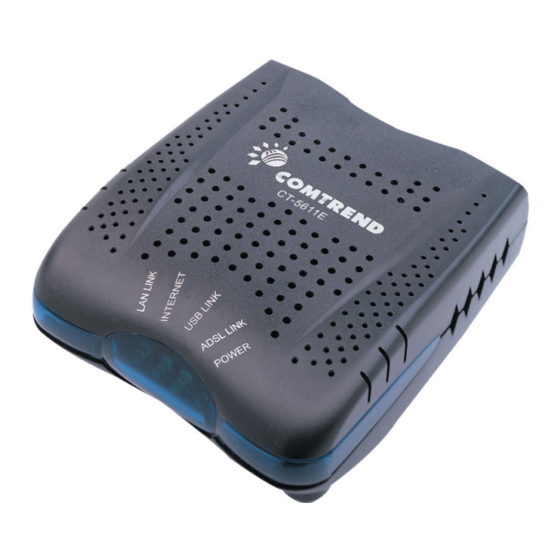
1.3 LED Indicators The LED indicators labeled in this top-down view are explained in the table below. Color Mode Function POWER Green The router is powered up. The router is powered down. ADSL LINK Green The ADSL link is established. The ADSL link is not established. -
Page 7: Chapter 2 Installation
Chapter 2 Installation 2.1 Hardware Installation Power Button Reset Button Follow the instructions below to complete the hardware installation. Connection to LINE - If you wish to connect both the router and a telephone, connect the LINE port to a POTS splitter with a RJ11 connection cable. Connection to LAN Use RJ45 cable to connect a network hub or PC. -
Page 8: Usb Driver Autorun Installation
2.2 USB Driver Autorun Installation Before connecting the CT-5611E to a PC with USB, the correct drivers must be installed. The auto-run USB driver installation supports Win ME, Win 98, Win 2000, Win XP (32 bit) and Vista (32 bit). For those using Windows XP 64 bit, the driver must be installed manually (please see section 2.3 below for details). - Page 9 STEP 2: The following window will be displayed. Click the Next button to continue. STEP 3: When the window displays as below, wait for the drivers to fully install. STEP 4: Click the Finish button, when the window displays as below.
- Page 10 STEP 5: The installation is complete. You can now connect the device to your PC using a standard USB cable.
-
Page 11: Usb Driver Manual Installation (64Bit Os)
2.3 USB Driver Manual Installation (64bit OS) Before connecting this router to a PC with USB, the correct drivers must be installed. Follow the procedure below to manually install the 64bit USB driver STEP 1: Connect the USB port to the PC by plugging the flat connector of a standard USB cable into your PC and plugging the square connector into the device. - Page 12 STEP 2: When the window displays as below, select Install from a list or specific location (Advanced) and then click the Next button. NOTE: This window won’t display if the USB Driver has been previously installed. In this case, contact technical support for assistance. STEP 3: Insert the installation CD.
- Page 13 STEP 4: Select the location of the file using the Browse button, as shown above. Normally, the file is on the CD-ROM shipped with the device. STEP 5: Locate the Vista folder, and click OK. STEP 6: When the window displays as below, click the NEXT button and wait.
- Page 15 STEP 7: Click the Finish button when the window displays as below. STEP 8: Installation is complete.
-
Page 16: Chapter 3 Web User Interface
Chapter 3 Web User Interface This section describes how to access the device via the web user interface using an Internet browser such as Microsoft Internet Explorer (version 5.0 and later). 3.1 Default Settings The following are the default settings for the device. •... - Page 17 STATIC IP Mode To configure the device manually, your PC must have a static IP address within the 192.168.1.x subnet. Follow the steps below to configure your PC IP address to use subnet 192.168.1.x. The following assumes you are running Windows XP. STEP 1: From the Network Connections window, open Local Area Connection (You may also access this screen by double-clicking the Local Area Connection icon on your taskbar).
-
Page 18: Login Procedure
STEP 2: Select Internet Protocol (TCP/IP) and click the Properties button. The screen should now display as below. Change the IP address to the domain of 192.168.1.x (1<x<254) with subnet mask of 255.255.255.0. STEP 3: Click OK to submit the settings. 3.3 Login Procedure Perform the following steps to login to the web user interface. - Page 19 Click OK to continue. NOTE: The login password can be changed later (see 8.4.3 Passwords) STEP 3: After successfully logging in for the first time, you will reach this screen. NOTE1: If a PVC connection already exists then this Quick Setup screen will be bypassed and the Device Info –...
-
Page 20: Chapter 4 Quick Setup
Chapter 4 Quick Setup After login, the Quick Setup screen will appear as shown. The Quick Setup screen allows the user to configure the ADSL router for DSL connectivity and Internet access. It also guides the user through the WAN network setup first and then the LAN interface setup. -
Page 21: Auto Quick Setup
4.1 Auto Quick Setup This function provides an automated process to quickly setup a WAN connection. The device will auto-detect the best PVC profile available, provided that the ADSL link is up. For manual setup, please skip to 4.2 Manual Quick Setup. -
Page 22: Manual Quick Setup
4.2 Manual Quick Setup STEP 1: Select Quick Setup from the main menu and uncheck the DSL Auto- connect checkbox to begin the manual quick setup process. Uncheck to begin the manual quick setup process and display the following screen. STEP 2: Adjust the VPI/VCI settings for the connection you wish to establish. -
Page 23: Ppp Over Atm (Pppoa) And Ppp Over Ethernet (Pppoe)
STEP 3: On this screen, you can choose the connection type and select the appropriate encapsulation mode. The available options are shown. PPPoA- VC/MUX, LLC/ENCAPSULATION PPPoE- LLC/SNAP BRIDGING, VC/MUX MER- LLC/SNAP-BRIDGING, VC/MUX IPoA- LLC/SNAP-ROUTING, VC MUX Bridging- LLC/SNAP-BRIDGING, VC/MUX NOTE: Please ignore the onscreen reference to 802.1q VLAN tagging;... - Page 24 PPP Username/PPP Password The PPP Username and the PPP password requirement are dependent on the particular requirements of the service provider. A maximum of 256 characters is allowed for the PPP user name and a maximum of 32 characters for PPP password. PPPoE service name For PPPoE service, PADI requests contain a service label.
- Page 25 Use Static IP Address Unless your service provider specially requires this setup, do not select it. If selected, enter your static IP address in the IP Address field. Also, do not forget to adjust your TCP/IP Settings as described in subsection 3.2 IP Configuration.
- Page 26 STEP 6: After entering your settings, click Next. The following screen appears. The Device Setup screen allows the user to configure the LAN interface IP address, subnet mask and DHCP server. To enable DHCP, select Enable DHCP server and enter starting and ending IP addresses and the leased time. This setting configures the router to automatically assign IP, default gateway and DNS server addresses to every PC on your LAN.
- Page 27 STEP 7: Click Next to display the WAN Setup - Summary screen that presents the entire configuration summary. Click Back to modify the settings. STEP 8: Click Save/Reboot to apply these settings. The configuration will be saved to flash memory and then the device will reboot. After the device reboots, the Web UI should refresh the browser window.
-
Page 28: Mac Encapsulation Routing (Mer)
4.2.2 MAC Encapsulation Routing (MER) Step 4: Select MAC Encapsulation Routing (MER) and enter information provided to you by your ISP to configure the WAN IP settings. Click Next. DHCP is enabled in MER mode when Obtain an IP address automatically is chosen. - Page 29 Step 5: Click Next to display the following screen. Enable NAT: If the LAN is configured with a private IP address, the user should select this checkbox. The NAT submenu will display after the next reboot. The user can then configure NAT-related features. If a private IP address is not used on the LAN side, this checkbox should not be selected to free up system resources for better performance.
- Page 30 Step 6: Upon completion, click Next. The following screen appears. The Device Setup screen allows the user to configure the LAN interface IP address, subnet mask and DHCP server. To enable DHCP, select Enable DHCP server and enter starting and ending IP addresses and the leased time. This setting configures the router to automatically assign IP, default gateway and DNS server addresses to every PC on your LAN.
- Page 31 STEP 7: Click Next to display the WAN Setup - Summary screen that presents the entire configuration summary. Click Back to modify the settings. STEP 8: Click Save/Reboot to apply these settings. The configuration will be saved to flash memory and then the device will reboot. After the device reboots, the Web UI should refresh the browser window.
-
Page 32: Ip Over Atm
4.2.3 IP Over ATM Step 4: Select IP over ATM (IPoA) and click Next. The following screen appears. NOTE: Since DHCP is not supported over IPoA, users must manually enter the IP address or WAN interface for the default gateway and the DNS server addresses (primary and secondary), as provided by their ISP. - Page 33 Enable IGMP Multicast (Proxy): Tick the checkbox to enable IGMP multicast. IGMP (Internet Group Membership Protocol) is a protocol used by IP hosts to report their multicast group memberships to any immediately neighboring multicast routers. Enable WAN Service: Tick the checkbox to enable WAN service. Service Name: This is the WAN Service label.
-
Page 34: Bridging
STEP 7: Click Next to display the WAN Setup - Summary screen that presents the entire configuration summary. Click Back to modify the settings. STEP 9: Click Save/Reboot to apply these settings. The configuration will be saved to flash memory and then the device will reboot. After the device reboots, the Web UI should refresh the browser window. - Page 35 Step 5: Click the Next button to continue. On this screen, you may enter the IP address and Subnet Mask for the LAN interface. Click Next. NOTE: The LAN IP interface in bridge mode is needed for local users to manage the device.
-
Page 36: Chapter 5 Device Information
Chapter 5 Device Information The web user interface is divided into two windowpanes, the main menu (at left) and the display screen (on the right). The main menu has the following options: Device Info, Advanced Setup, Diagnostics, and Management. Selecting one of these options will open a submenu with individual screen functions. -
Page 37: Wan
5.1 WAN Select WAN from the Device Info submenu to display the configured PVC(s). VPI/VCI Shows the values of the ATM VPI/VCI Con. ID Shows the connection ID Category Shows the ATM service classes Service Shows the name for WAN connection Interface Shows connection interfaces Protocol... -
Page 38: Statistics
5.2 Statistics The Statistics submenu provides detailed information for LAN and WAN interfaces. NOTE: These statistics refresh every 15 seconds. 5.2.1 LAN Statistics This screen shows statistics for the Ethernet interface on the LAN. Interface Shows connection interfaces Received/Transmitted - Bytes Rx/TX (receive/transmit) packet in bytes - Pkts Rx/TX (receive/transmit) packets... -
Page 39: Atm Statistics
Service WAN service label VPI/VCI ATM Virtual Path/Channel Identifiers Protocol Connection type (e.g. PPPoE, IPoA, Bridge) Interface Shows connection interfaces in the following format: nas_(VPI number_VCI number). These interfaces are devised by the system and not the user. Received/Transmitted - Bytes Rx/TX (receive/transmit) packet in bytes - Pkts Rx/TX (receive/transmit) packets... -
Page 40: Adsl Statistics
ATM AAL5 Layer Statistics over ADSL interface Field Description In Octets Number of received AAL5/AAL0 CPCS PDU octets Out Octets Number of received AAL5/AAL0 CPCS PDUs octets transmitted In Ucast Pkts Number of received AAL5/AAL0 CPCS PDUs passed to a higher-layer for transmission Out Ucast Pkts Number of received AAL5/AAL0 CPCS PDUs received from a... - Page 42 Field Description Mode G.DMT, G.lite, T1.413, ADSL2, ADSL2+ Type Channel type Interleave or Fast Line Coding Trellis On/Off Status Lists the status of the DSL link Link Power State Link output power state. SNR Margin (dB) Signal to Noise Ratio (SNR) margin Attenuation (dB) Estimate of average loop attenuation in the downstream direction.
-
Page 43: Route
Within the ADSL Statistics window, a Bit Error Rate (BER) test can be started using the ADSL BER Test button. A small window will open when the button is pressed; it will appear as shown below. Click Start to start the test or Close. If the test is successful, the pop-up window will display as follows. - Page 44 Field Description Destination Destination network or destination host Gateway Next hub IP address Subnet Mask Subnet Mask of Destination Flag U: route is up !: reject route G: use gateway H: target is a host R: reinstate route for dynamic routing D: dynamically installed by daemon or redirect M: modified from routing daemon or redirect Metric...
-
Page 45: Arp
5.4 ARP Click ARP to display the ARP information. Field Description IP address Shows IP address of host pc Flags Complete Incomplete Permanent Publish HW Address Shows the MAC address of host pc Device Shows the connection interface... -
Page 46: Dhcp
5.5 DHCP Click DHCP to display all DHCP Leases. Field Description Hostname Shows the device/host/PC network name MAC Address Shows the Ethernet MAC address of the device/host/PC IP address Shows IP address of device/host/PC Expires In Shows how much time is left for each DHCP Lease... -
Page 47: Chapter 6 Advanced Setup
Chapter 6 Advanced Setup This chapter explains the following advanced setup screens: 6.1 WAN 6.5 Quality of Service 6.2 LAN 6.6 Routing 6.3 NAT 6.7 DNS 6.4 Security 6.8 DSL 6.1 WAN Follow these steps to configure WAN interfaces. STEP 1: To Add a new WAN connection, click the Add button. To edit an existing connection, click the Edit button next to the connection. -
Page 48: Lan
To complete the Add or Edit go to STEP 2 in section 4.2 Manual Quick Setup. 6.2 LAN This screen allows the user to configure the LAN Interface on the device. It is similar to the DEVICE SETUP screen in Quick Setup, but with more options. NOTE: NAT is disabled above so UPnP is hidden (see underlined notes below). -
Page 49: Nat
IP Address: Enter the IP address for the LAN port. Subnet Mask: Enter the subnet mask for the LAN port. Enable UPnP: Tick the box to enable Universal Plug and Play. This option is hidden when NAT disabled or if no PVC exists Enable IGMP Snooping: Enable by ticking the checkbox. -
Page 50: Virtual Servers
6.3.1 Virtual Servers Virtual Servers allow you to direct incoming traffic from the WAN side (identified by Protocol and External port) to the Internal server with private IP addresses on the LAN side. The Internal port is required only if the external port needs to be converted to a different port number used by the server on the LAN side. -
Page 51: Port Triggering
Custom Server User can enter the name of their choice. Server IP Address Enter the IP address for the server. External Port Start Enter the starting external port number (when you select Custom Server). When a service is selected the port ranges are automatically configured. -
Page 52: Dmz Host
Select Application User should select the application from the list. Custom Application User can enter the name of their choice. Trigger Port Start Enter the starting trigger port number (when you select custom application). When an application is selected the port ranges are automatically configured. -
Page 53: Security
Each network device has a unique 48-bit MAC address. This can be used to filter (block or forward) packets based on the originating device. MAC filtering policy and rules for the CT-5611E can be set according to the following procedure. The policy FORWARDED means that all MAC layer frames will be FORWARDED except those matching the rules specified in the following table. - Page 54 Choose Add or Remove to configure MAC filtering rules. The following screen will appear when you click Add. Create a filter to identify the MAC layer frames by specifying at least one condition below. If multiple conditions are specified, all of them must be met.
-
Page 55: Ip Filtering
6.4.2 IP Filtering This screen sets filter rules that limit IP traffic (Outgoing/Incoming). Multiple filter rules can be set and each applies at least one limiting condition. For individual IP packets to pass the filter all conditions must be fulfilled. NOTE: This function is not available when in bridge mode. - Page 56 Incoming IP Filter The default setting for all Incoming traffic is BLOCKED. Under this condition, only those incoming IP packets that match the filter rules will be ACCEPTED. To add a filtering rule, click the Add button. The following screen will display. For detailed field descriptions, please reference the Outgoing IP Filter table.
-
Page 57: Parental Control
6.4.3 Parental Control This feature restricts access from a LAN device to an outside network through the device on selected days at certain times. Make sure to activate the Internet Time server synchronization as described in section 8.3 Internet Time, so that the scheduled times match your local time. -
Page 58: Quality Of Service
6.5 Quality of Service NOTE: QoS must be enabled in at least one PVC to display this option. (see Advanced Setup - WAN for detailed PVC setup instructions). Click Add to configure network traffic classes. The following screen will display:... - Page 59 Traffic Class Name Enter name for traffic class Assign ATM Transmit Priority Select Low, Medium or High. Mark IP Precedence Select between 0-7. The lower the digit shows the higher the priority Mark IP Type Of Service Select either: Normal Service, Minimize Cost, Maximize Reliability, Maximize Throughput, Minimize Delay Mark 802.1p if 802.1q is enabled...
-
Page 60: Routing
6.6 Routing This option allows for Default Gateway and Static Route configuration. NOTE: In Bridge mode, these options are shown but have no effect. 6.6.1 Default Gateway If the Enable Automatic Assigned Default Gateway checkbox is selected, this device will accept the first received default gateway assignment from one of the enabled PVC(s). -
Page 61: Dns
Click the Add button to display the following screen. Enter Destination Network Address, Subnet Mask, Gateway IP Address and/or WAN Interface. Then click Save/Apply to add the entry to the routing table. 6.7 DNS 6.7.1 DNS Server If the Enable Automatic Assigned DNS checkbox is selected, this device will accept the first received DNS assignment from one of the DHCP enabled PVC(s) –... -
Page 62: Dynamic Dns
6.7.2 Dynamic DNS The Dynamic DNS service allows a dynamic IP address to be aliased to a static hostname in any of many domains, allowing the CT-5611E to be more easily accessed from various locations on the Internet. To add a dynamic DNS service, click the Add button and this screen will display. - Page 63 D-DNS provider Select a dynamic DNS provider from the list Hostname Enter the name for the dynamic DNS server. Interface Select the interface from the list Username Enter the username for the dynamic DNS server. Password Enter the password for the dynamic DNS server.
-
Page 64: Dsl
6.8 DSL The DSL Settings screen allows for the selection of DSL modulation modes. For optimum performance, the modes selected should match those of your ISP. Modulation Data Transmission Rate - Mbit/s (Megabits per second) G.Dmt Downstream: 12 Mbit/s Upstream: 1.3 Mbit/s G.lite Downstream: 4 Mbit/s... -
Page 65: Chapter 7 Diagnostics
Chapter 7 Diagnostics The Diagnostics menu provides feedback on the connection status of the router. The individual tests are listed below. If a test displays a fail status, click the Test button at the bottom of the screen to retest and confirm the error. If the test continues to fail, click Help and follow the troubleshooting procedures. - Page 66 Ping Default Gateway Pass: Indicates that the router can communicate with the first entry point to the network. It is usually the IP address of the ISP local router. Fail: Indicates that the router was unable to communicate with the first entry point on the network. It may not have an effect on your Internet connectivity.
-
Page 67: Chapter 8 Management
Chapter 8 Management The Management menu has the following maintenance functions and processes: 8.1 Settings 8.4 Access Control 8.2 System Log 8.5 Update Software 8.3 Internet Time 8.6 Save and Reboot 8.1 Settings The Settings screen allows for the backup, retrieval and restoration of settings. 8.1.1 Backup Settings Select Backup from the Settings submenu to access the screen shown below. -
Page 68: Restore Default
8.1.3 Restore Default Select Restore Default from the Settings submenu to access the screen shown below. Click the Restore Default Settings button to restore the router to the default firmware settings. Restoring system settings require a reboot. NOTE: The default settings can be found in section 3.1 Default Settings. -
Page 69: System Log
8.2 System Log The System Log option under Management allows for the viewing of system events and configuration of related options. The default setting for the System Log is enabled. Follow the steps below to enable and view the System Log. STEP 1: Click Configure System Log to begin. - Page 70 The events ranging from the highest critical level “Emergency” down to this configured level will be recorded to the log buffer on the CT-5611E SDRAM. When the log buffer is full, the newest event will wrap up to the top of the log buffer and overwrite the oldest event.
-
Page 71: Internet Time
8.3 Internet Time The Internet Time option under the Management submenu configures the time settings of the device. To automatically synchronize with Internet timeservers, tick the corresponding box displayed on this screen shown below. First NTP timeserver: Select the required server. Second NTP timeserver: Select second timeserver, if required. -
Page 72: Access Control
8.4 Access Control The Access Control option under the Management menu bar configures access related parameters in three areas: Services, IP Addresses, and Passwords. Use Access Control to control local and remote management settings for the device. NOTE: The WAN column is present if the WAN interface is active. Only the LAN side will be displayed if the WAN interface is down. -
Page 73: Passwords
On this screen, enter the IP address, subnet mask and interface to which you wish to give management permissions. Click Save/Apply to continue. 8.4.3 Passwords The Passwords option configures the user account access passwords for the device. Access to the device is limited to the following three user accounts: •... -
Page 74: Update Software
8.5 Update Software The Update Software screen allows for firmware updates. Manual device upgrades from a locally stored file can be performed using the following screen. Step 1: Obtain an updated software image file from your ISP. Step 2: Enter the path and filename of the firmware image file in the Software File Name field or click the Browse button to locate the image file. -
Page 75: Save And Reboot
8.6 Save and Reboot This function saves the current configuration settings and reboots the device. NOTE1: You may need to reconfigure the TCP/IP settings after rebooting. For example, if the DHCP server is disabled Static IP settings must be configured. See section 3.2 IP Configuration for detailed instructions. -
Page 76: Appendix A: Pin Assignments
Appendix A: Pin Assignments Line Port (RJ11) Definition Definition ADSL_TIP ADSL_RING LAN Port (RJ45) Definition Definition Transmit data+ Transmit data- Receive data- Receive data+... -
Page 77: Appendix B: Specifications
Appendix B: Specifications Rear Panel RJ-11 X1 for ADSL, RJ-45 X 1 for LAN, USB X 1 for LAN, Reset Button X 1, Power switch X 1 ADSL ITU-T G.992.5, ITU-T G.992.3, ITU-T G.992.1, ANSI T1.413 Issue 2 G.992.5 (ADSL2+) Downstream: 24 Mbps Upstream: 1.3 Mbps G.992.3 (ADSL2) - Page 78 Power External power adapter ......110 Vac or 220 Vac Environmental Tolerance Operating temperature ......0 ~ 50 degrees Celsius Relative humidity ........5 ~ 90% (non-condensing) Dimensions ......92 mm (W) x 34 mm (H) x 114 mm (D) Certifications......FCC Part 15 class B, FCC Part 68 NOTE: Specifications are subject to change without notice...
-
Page 79: Appendix C: Security
Appendix C: Security Stateful Packet Inspection Refers to an architecture, where the firewall keeps track of packets on each connection traversing all its interfaces and makes sure they are valid. This is in contrast to static packet filtering which only examines a packet based on the information in the packet header. - Page 80 Filter Name : Out_Filter2 Protocol : UDP Source Address : 192.168.1.45 Source Subnet Mask : 255.255.255.0 Source Port : 5060:6060 Destination Address : 172.16.13.4 Destination Subnet Mask : 255.255.255.0 Destination Port : 6060:7070 This filter will drop all UDP packets coming from LAN with IP Address/ Subnet Mask 192.168.1.45/24 and a source port in the range of 5060 to 6060, destined to 172.16.13.4/24 and a destination port in the range of 6060 to 7070.
- Page 81 Example 2: Filter Name : In_Filter2 Protocol : UDP Source Address : 210.168.219.45 Source Subnet Mask : 255.255.0.0 Source Port : 5060:6060 Destination Address : 192.168.1.45 Destination Subnet Mask : 255.255.255.0 Destination Port : 6060:7070 This rule will ACCEPT all UDP packets coming from WAN interface mer_0_35/nas_0_35 with IP Address/Subnet Mask 210.168.219.45/16 and a source port in the range of 5060 to 6060, destined to 192.168.1.45/24 and a destination port in the range of 6060 to 7070.
- Page 82 Global Policy: Blocked Protocol Type: PPPoE Destination MAC Addr: 00:12:34:56:78:90 Source MAC Addr: 00:34:12:78:90:56 Frame Direction: WAN => LAN WAN Interface Selected: br_0_34/nas_0_34 Addition of this rule forwards all PPPoE frames going from WAN-side to LAN-side with a Destination MAC Address of 00:12:34:56:78 and Source MAC Address of 00:34:12:78:90:56 on the br_0_34 WAN interface.
Need help?
Do you have a question about the CT-5611E and is the answer not in the manual?
Questions and answers