
Related Manuals for Comtrend Corporation CT-5621


Summary of Contents for Comtrend Corporation CT-5621
- Page 1 CT-5621 ADSL2+ Multi-Port Router User’s Manual Version A1.7, November 9, 2007 261055-016...
- Page 2 Copyright Copyright© 2007 Comtrend Corporation. All rights reserved. The information and messages contained herein are proprietary to Comtrend Corporation. No part of this document may be translated, transcribed, reproduced, in any form, or by any means without prior written permission by Comtrend Corporation.
-
Page 3: Table Of Contents
Table of Contents CHAPTER 1 INTRODUCTION ......................4 ..........................4 EATURES ..........................5 PPLICATION LED I ....................6 RONT ANEL NDICATORS CHAPTER 2 INSTALLATION ......................7 ......................7 ARDWARE NSTALLATION USB D ..............8 EVICE RIVER NSTALLATION USB D OS)..............11 RIVER ANUAL NSTALLATION CHAPTER 3 LOGIN VIA THE WEB BROWSER ..............16 IP A ..........................16 DDRESS... - Page 4 NAT ............................53 6.3.1 Virtual Servers ........................53 6.3.2 Port Triggering .......................55 6.3.3 DMZ Host ........................57 6.3.4 ALG ..........................58 ..........................59 ECURITY 6.4.1 IP Filtering ........................59 6.4.2 Parental Control ......................62 6.4.3 MAC Filtering.........................63 ......................65 UALITY OF ERVICE ..........................67 OUTING 6.6.1 Default Gateway ......................67 6.6.2 Static Route........................68 6.6.3...
- Page 5 APPENDIX C: SPECIFICATIONS....................100 APPENDIX D: SSH CLIENT ......................102...
-
Page 6: Chapter 1 Introduction
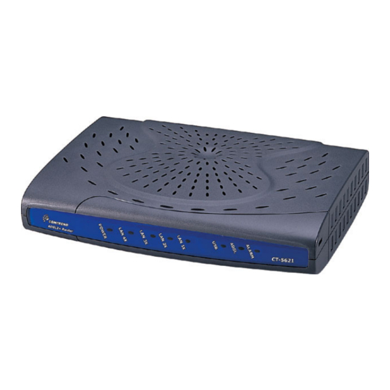
Chapter 1 Introduction The CT-5621 is a wired Local Area Network ADSL2+ multi-port router. Four 10/100 Base-T Ethernet ports provide wired LAN. The CT-5621 ADSL2+ multi-port router provides state of the art security features such as Firewall and VPN pass through. -
Page 7: Application
Application The following diagram depicts the application of the CT-5621. -
Page 8: Front Panel Led Indicators
Front Panel LED Indicators The front panel LEDs are shown in the picture below, followed by an explanation in the table below. Color Mode Function POWER Green The router is powered up. The router is powered down. Green An Ethernet Link is established. 4x~1x An Ethernet Link is not established. -
Page 9: Chapter 2 Installation
Chapter 2 Installation Hardware Installation In the rear panel, there is a reset button. To load the factory default settings, hold the reset button down for at least 5 seconds. Reset button Follow the instructions below to complete the hardware connections. Connection to LINE port If you wish to connect both the router and a telephone, connect the LINE port to a POTS splitter with a RJ11 connection cable. -
Page 10: Usb Device Driver Auto-Run Installation
USB Device Driver Auto-run Installation Before you connect your router’s USB cable to your PC, you must load the ADSL USB drivers. The auto-run USB driver installation supports Win ME, Win 98, Win 2000, Win XP (32 bit) and Vista (32 bit). For those using Windows XP 64 bit, the driver needs to be installed manually (please see section 2.3 below for details), and the driver is also enclosed on the CD-ROM. - Page 11 STEP 2: The following screen will be displayed. Click the Next button to continue. STEP 3: When the screen displays as below, wait until the drivers are fully installed.
- Page 12 STEP 4: Click the Finish button, when the screen displays as below. STEP 5: Installation is complete.
-
Page 13: Usb Driver Manual Installation(64Bit Os)
USB Driver Manual Installation(64bit OS) Before you connect your router’s USB cable to your PC, you must load the ADSL USB drivers. This manual USB driver installation supports Windows XP 64 bit. To connect the router to a PC using the USB interface, you need to use a standard USB cable and install the USB interface software. - Page 14 STEP 2: When the screen displays as below, select install from a list of specific location (Advanced) and click the Next button. Note: This screen won’t be displayed if the USB Driver has been previously un/installed. STEP 3: If you are installing the software from a disk, insert the disk. Note: When the auto-run screen pops up click Exit and continue with the manual installation process (see below).
- Page 15 STEP 4: Select the location of the file using the Browse button. Normally, the file is on the CD-ROM shipped with the device. STEP 5: Locate the Vista folder, and click the OK button.
- Page 16 STEP 6: When the screen displays as below, click the NEXT button.
- Page 17 STEP 7: Click the Finish button, when the screen displays as below. STEP 8: Installation is complete.
-
Page 18: Chapter 3 Login Via The Web Browser
IP Address The default IP address of the CT-5621 (LAN port) is 192.168.1.1 and the default private address range provided by the ISP server in the router is 192.168.1.2 -192.168.1.254. To configure the CT-5621 for the first time, the configuration PC must have a static IP address within the 192.168.1.x subnet. -
Page 19: Login Procedure
Perform the following steps to bring up the Web user interface and configure the CT-5621. To log on to the system from the Web browser, follow the steps below: STEP 1: Start your Internet browser. Type the IP address for the router in the Web address field. -
Page 20: Default Settings
Default Settings During power on initialization, the CT-5621 initializes all configuration attributes to default values. It will then read the configuration profile from the Permanent Storage section in flash memory. The default attributes are overridden when identical attributes with different values are configured. The configuration profile in Permanent Storage can be created via the Web user interface or telnet user interface, or other management protocols. -
Page 21: Chapter 4 Device Info
Chapter 4 Device Info After login, the Device Info - Summary screen appears as shown. Note: The selections available on the left side menu are based upon user permissions. -
Page 22: Wan
Click Device Info on the menu bar to display the WAN option. Then, click WAN on the Device Info menu bar to display the configured PVC(s) and the status. VPI/VCI Shows the values of the ATM VPI/VCI Con. ID Shows the connection ID Category Shows the ATM service classes Service... -
Page 23: Statistics
Statistics Selection of the Statistics screen provides statistics for the Network Interface of LAN, WAN, ATM and ADSL. All statistics screens are updated every 15 seconds. -
Page 24: Lan Statistics
4.2.1 LAN Statistics The Network Statistics screen shows interface statistics for ATM AAL5 interface, Ethernet and USB interfaces. (The Network Statistics screen shows the interface statistics for the LAN interface. Here provides byte transfer, packet transfer, Error and Drop statistics for the LAN interface.) -
Page 25: Wan Statistics
4.2.2 WAN Statistics Service Shows the service type VPI/VCI Shows the values of the ATM VPI/VCI Protocol Shows the connection type, such as PPPoE, PPPoA, etc. Interface Shows connection interfaces Received/Transmitted - Bytes Rx/TX (receive/transmit) packet in Bytes - Pkts Rx/TX (receive/transmit) packets - Errs Rx/TX (receive/transmit) the error packets... -
Page 26: Atm Statistics
4.2.3 ATM statistics The following figure shows the ATM statistics screen. ATM Interface Statistics Field Description In Octets Number of received octets over the interface Out Octets Number of transmitted octets over the interface In Errors Number of cells dropped due to uncorrectable HEC errors In Unknown Number of received cells discarded during cell header validation, including cells with unrecognized VPI/VCI values, and cells with... - Page 27 ATM AAL5 Layer Statistics over ADSL interface Field Description In Octets Number of received AAL5/AAL0 CPCS PDU octets Out Octets Number of received AAL5/AAL0 CPCS PDUs octets transmitted In Ucst Pkts Number of received AAL5/AAL0 CPCS PDUs passed to a higher-layer for transmission Out Ucast Pkts Number of received AAL5/AAL0 CPCS PDUs received from a...
-
Page 28: Adsl Statistics
4.2.4 ADSL Statistics The following figure shows the ADSL Network Statistics screen. Within the ADSL Statistics window, a bit Error Rate Test can be started using the ADSL BER Test button. The Reset button resets the statistics. - Page 29 Field Description Mode Line Coding format, that can be selected G.dmt, G.lite, T1.413, ADSL2, ADSL2+ Type Channel type Interleave or Fast Line Coding Trellis On/Off Status Lists the status of the DSL link Link Power State Link output power state. SNR Margin (dB) Signal to Noise Ratio (SNR) margin Attenuation (dB)
-
Page 30: Route
4.2.5 Route Choose Route to display the routes that the route information has learned. 4.2.6 Click ARP to display the ARP information. -
Page 31: Dhcp
4.2.7 DHCP Click DHCP to display the DHCP information. -
Page 32: Chapter 5 Quick Setup
If the service provider provides PPPoE service, then the connection selection depends on whether the LAN-side device (typically a PC) is running a PPPoE client or whether the CT-5621 is to run the PPPoE client. The CT-5621 can support both cases simultaneously. -
Page 33: Auto Quick Setup
Note: Up to eight PVC profiles can be configured and saved on the flash memory. To activate a particular PVC profile, you need to navigate all the Quick Setup pages until the last summary page, then click on the Finish button and reboot the system. Auto Quick Setup The auto quick setup requires the ADSL link to be up. -
Page 34: Manual Quick Setup
Manual Quick Setup STEP 1: Click Quick Setup and un-tick the DSL Auto-connect checkbox to enable manual configuration of the connection type. Un-tick this checkbox to enable manual setup and display the following screen. STEP 2: Enter the Virtual Path Identifier (VPI) and Virtual Channel Identifier (VCI). Select Enable Quality Of Service if required. - Page 35 STEP 3: STEP 3: Then, choose the Encapsulation mode. Select Enable 802.1q (by ticking the box) if required, and input a number for the VLAN ID. Click Next. STEP 4: Click Next to display the following screen. Choosing different connection types pops up different settings requests.
-
Page 36: Ppp Over Atm (Pppoa) And Ppp Over Ethernet (Pppoe)
5.2.1 PPP over ATM (PPPoA) and PPP over Ethernet (PPPoE) 1. Select the PPP over ATM (PPPoA) or PPP over Ethernet (PPPoE) radio button and click Next. The following screen appears: PPP USERNAME/PPP PASSWORD/ PPPOE SERVICE NAME: The PPP Username, PPP password and the PPPoE Service Name entries are dependent on the particular requirements of the ISP or the ADSL service provider. - Page 37 Disconnect if no activity The CT-5621 can be configured to disconnect if there is no activity for a period of time by selecting the Dial on demand check box. When the checkbox is ticked, you need to enter the inactivity timeout period. The timeout period ranges from 1 minute to 4320 minutes.
- Page 38 2. Click Next to display the following screen. Enable IGMP Multicast checkbox: Tick the checkbox to enable IGMP multicast (proxy). IGMP (Internet Group Membership Protocol) is a protocol used by IP hosts to report their multicast group memberships to any immediately neighboring multicast routers.
- Page 39 3. After entering your settings, select Next. The following screen appears. This page allows the user to configure the LAN interface IP address, subnet mask and DHCP server. If the user would like this ADSL router to assign dynamic IP address, DNS server and default gateways to other LAN devices, select the button Enable DHCP server on the LAN to enter the starting IP address and end IP address and DHCP leased time.
- Page 40 The Web UI will not respond until the system is brought up again. After the system is up, the Web UI will refresh to the Device Info page automatically. The CT-5621 is ready for operation and the LEDs display as described in the LED description tables.
-
Page 41: Mac Encapsulation Routing (Mer)
5.2.2 MAC Encapsulation Routing (MER) To configure MER, do the following. 1. Select Quick Setup and click Next. 2. Enter the PVC Index provided by the ISP and click Next. 3. Select the MAC Encapsulation Routing (MER) radio button, and click Next. The following screen appears. - Page 42 4. Click Next to display the following screen. Enable NAT checkbox: If the LAN is configured with a private IP address, the user should select this checkbox. The NAT submenu on the left side main panel will be displayed after reboot. The user can then configure NAT-related features after the system comes up.
- Page 43 5. Upon completion, click Next. The following screen appears. The Device Setup page allows the user to configure the LAN interface IP address and DHCP server. If the user would like this ADSL router to assign dynamic IP addresses, DNS server and default gateway to other LAN devices, select the radio box Enable DHCP server on the LAN to enter the starting IP address and end IP address and DHCP lease time.
- Page 44 The Web UI will not respond until the system is brought up again. After the system is up, the Web UI will refresh to the Device Info page automatically. The CT-5621 is ready for operation and the LEDs display as described in the LED description tables.
-
Page 45: Ip Over Atm
5.2.3 IP Over ATM To configure IP Over ATM, 1. Select Quick Setup and click Next. 2. Enter the PVC Index and click Next. 3. Type the VPI and VCI values provided by the ISP and click Next. 4. Select the IP over ATM (IPoA) radio button and click Next. The following screen appears. - Page 46 Enable NAT checkbox If the LAN is configured with a private IP address, the user should select this checkbox. The NAT submenu on the left side main panel will be displayed after reboot. The user can then configure NAT-related features after the system comes up.
- Page 47 The user must configure the IP Address and the Subnet Mask. To use the DHCP service on the LAN, select the Enable DHCP server checkbox, and enter the Start IP addresses, the End IP address and DHCP lease time. This configures the router to automatically assign IP addresses, default gateway address and DNS server addresses to each of your PCs.
- Page 48 The Web UI will not respond until the system is brought up again. After the system is up, the Web UI will refresh to the Device Info page automatically. The CT-5621 is ready for operation and the LEDs display as described in the LED description tables.
-
Page 49: Bridging
5.2.4 Bridging Select the bridging mode. To configure Bridging, do the following. 1. Select Quick Setup and click Next. 2. Enter the PVC Index and click Next. 3. Type in the VPI and VCI values provided by the ISP and click Next. 4. - Page 50 6. Click Next and the following screen will be displayed The WAN Setup-Summary screen presents the entire configuration summary. Click Save/Reboot if the settings are correct. Click Back if you wish to modify the settings.
-
Page 51: Chapter 6 Advanced Setup
Chapter 6 Advanced Setup This chapter explains: WAN, LAN, Routing, DSL and Port Mapping…... Note: Shown below for your reference are the available menu options for each different configuration. This screenshot is for MER and IPoA encapsulations. This screenshot is for PPPoE and PPPoA encapsulations. - Page 52 This screenshot is for Bridge encapsulation.
-
Page 53: Wan
For further information on WAN please reference section: 4.1 WAN. VlanID • This function means one can add an 802.1Q VLAN tag on PPPoE/MER or Bridge mode. It means the packets are sent to WAN and a specific VlanID (802.1Q tag) will be added in the Ethernet header. The VlanID shows which 802.1Q tag will be added. -
Page 54: Lan
Configure the DSL Router IP Address and Subnet Mask for LAN interface. Save button only saves the LAN configuration data. Save/Reboot button saves the LAN configuration data and reboots the router to make the new configuration effective. IP Address: Enter the IP address for the LAN port. Subnet Mask: Enter the subnet mask for the LAN port. -
Page 55: Nat
To display the NAT function, you need to enable the NAT feature in the WAN Setup. Note: This function is enabled by default in PPPoE and PPPoA modes, disabled by default in MER and IPoA modes, and unavailable in Bridging mode. 6.3.1 Virtual Servers Virtual Server allows you to direct incoming traffic from WAN side (identified by... - Page 56 Sele ct a Service r should select the service from the list. Custom Server User can enter the name of their cho ice. Server IP Address Enter the IP address for the server. External Port Start Enter the starting external port number (when you select Custom Server).
-
Page 57: Port Triggering
6.3.2 Port Triggering Some applications require that specific ports in the Router's firewall be opened for access by the remote parties. Port Trigger dynamically opens up the 'Open Ports' in the firewall when an application on the LAN initiates a TCP/UDP connection to a remote party using the 'Triggering Ports'. - Page 58 Select an Application User should select the application from the list. Or Custom Application Or User can enter the name of their choice. Trigger Port Start Enter the starting trigger port number (when you select custom application). When an application is selected the port ranges are automatically configured.
-
Page 59: Dmz Host
6.3.3 DMZ Host The DSL router will forward IP packets from the WAN that do not belong to any of the applications configured in the Virtual Servers table to the DMZ host computer. Enter the computer's IP address and click "Apply" to activate the DMZ host. Clear the IP address field and click "Apply"... -
Page 60: Alg
6.3.4 SIP ALG is Application layer gateway. If the user has an IP phone (SIP) or VoIP gateway (SIP) behind the ADSL router, the SIP ALG can help VoIP packet passthrough the router (NAT enabled). Note: SIP (Session Initiation Protocol, RFC3261) is the protocol of choice for most VoIP (Voice over IP) phones to initiate communication. -
Page 61: Security
Security To display the Security function, you need to enable the firewall in WAN Setup. 6.4.1 IP Filtering IP filtering allows you to create a filter rule to identify outgoing/incoming IP traffic by specifying a new filter name and at least one condition below. All of the specified conditions in this filter rule must be satisfied for the rule to take effect. - Page 62 Filter Name Type a name for the filter rule. Protocol User can select from: TCP, TCP/UDP, UDP or ICMP. Source IP address Enter source IP address. Source Subnet Mask Enter source subnet mask. Source Port (port or port:port) Enter source port number. Destination IP address Enter destination IP address.
- Page 63 Incoming Note: The default setting for all Incoming traffic is BLOCKED. To ALLOW incoming traffic an IP filter must be added. To add a filtering rule, simply click the Add button. The following screen will be displayed. To configure the parameters, please reference Outgoing table above.
-
Page 64: Parental Control
6.4.2 Parental Control Parental control: allows parents, schools, and libraries to set access times for Internet use. To add a parental control, simply click the Add button. The following screen will be displayed. Username: Input Internet access user name MAC: Set the MAC address to access the Internet Mon, Tue, Wed, Thu, Fri, Sat, Sun: Set which days that will have block... -
Page 65: Mac Filtering
6.4.3 MAC Filtering Mac Filtering is only available when Bridging PVC is configured. Each network device has a unique MAC address. You can block or forward the packets based on the MAC addresses. The MAC Filtering Setup screen allows setting up the MAC filtering policy and the MAC filtering rules. MAC Filtering is only effective on ATM PVCs configured in Bridge mode. - Page 66 Option Description Protocol type PPPoE, IPv4, IPv6, AppleTalk, IPX, NetBEUI, IGMP Destination MAC Address Define the destination MAC address Source MAC Address Define the source MAC address Frame Direction: Select a direction of the frame WAN Interface Selects the interface that the MAC filter rule(s) will be applied.
-
Page 67: Quality Of Service
Quality of Service To display the Security function, you need to enable the QoS feature in the WAN Setup. Choose Add to configure network traffic classes. The following screen will be displayed:... - Page 68 Traffic Class Name Enter name for traffic class Priority Select Low, Medium or High. IP Precedence Select between 0-7. The lower the digit shows the higher the priority IP Type Of Service Select either: Normal Service, Minimize Cost, Maximize Reliability, Maximize Throughput, Minimize Delay Physical LAN Port User can select from: ENET, ENET (1-4), USB...
-
Page 69: Routing
Routing The Routing dialog box allows you to configure Default gateway, Static Route and RIP. 6.6.1 Default Gateway If ‘Enable Automatic Assigned Default Gateway’ checkbox is selected, this router will accept the first received default gateway assignment from one of the PPPoA, PPPoE or MER/DHCP enabled PVC(s). -
Page 70: Static Route
6.6.2 Static Route Choose Static Route to display the Static Route screen. The Static Route screen lists the configured static routes, and allows configuring static routes. Choose Add or Remove to configure the static routes. To add static route, click the Add button to display the following screen. Enter the destination network address, subnet mask, gateway AND/OR available WAN interface then click Save/Apply to add the entry to the routing table. -
Page 71: Rip
6.6.3 To activate RIP for the device, select the 'Enabled' radio button for Global RIP Mode. To configure an individual interface, select the desired RIP version and operation, followed by placing a check in the 'Enabled' checkbox for the interface. Click the 'Save/Apply' button to save the configuration, and to start or stop RIP based on the Global RIP mode selected. -
Page 72: Dns
6.7.1 DNS Server If 'Enable Automatic Assigned DNS' checkbox is selected, this router will accept the first received DNS assignment from one of the PPPoA, PPPoE or MER/DHCP enabled PVC(s) during the connection establishment. If the checkbox is not selected, enter the primary and optional secondary DNS server IP addresses. -
Page 73: Dynamic Dns
6.7.2 Dynamic DNS The Dynamic DNS service allows you to alias a dynamic IP address to a static hostname in any of the many domains, allowing your DSL router to be more easily accessed from various locations on the Internet. To add a dynamic DNS service, simply click the Add button. - Page 74 D-DNS provider Select a dynamic DNS provider from the list Hostname Enter the name for the dynamic DNS server. Interface Select the interface from the list Username Enter the username for the dynamic DNS server. Password Enter the password for the dynamic DNS server.
-
Page 75: Dsl
To access the DSL settings, First click On Advanced Setup and then click on DSL. The DSL Settings dialog box allows you to select an appropriate modulation mode. Option Description G.dmt Enabled Sets G.Dmt if you want the system to use G.Dmt mode. G.Lite Enabled Sets G.Lite if you want the system to use G.Lite mode. -
Page 76: Port Mapping
Port Mapping Port Mapping supports multiple ports to PVC and bridging groups. Each group will perform as an independent network. To support this feature, you must create mapping groups with appropriate LAN and WAN interfaces using the Add button. The Remove button will remove the grouping and add the ungrouped interfaces to the Default group. -
Page 77: Chapter 7 Diagnostics
To create a group from the list, first enter the group name and then select from the available interfaces on the list. Chapter 7 Diagnostics The Diagnostics menu provides feedback on the connection status of the CT-5621 and the ADSL link. The individual tests are listed below. If a test displays a fail... - Page 78 status, click Rerun Diagnostic Tests at the bottom of this page to make sure the fail status is consistent. If the test continues to fail, click Help and follow the troubleshooting procedures. Test Description Ethernet Connection Pass: indicates that the Ethernet interface from your computer is connected to the LAN port of your DSL Router.
- Page 79 ADSL Pass: Indicates that the DSL modem has detected a DSL Synchronization signal from the telephone company. A solid WAN LED on the router also indicates the detection of a DSL signal from the telephone company. Fail: indicates that the DSL modem does not detect a signal from the telephone company’s DSL network.
-
Page 80: Chapter 8 Management
Chapter 8 Management The Management section of the CT-5621 supports the following maintenance functions and processes: • Settings • System Log • SNMP Agent • Internet Time • Access Control • Update software • Save/Reboot Settings The Settings option allows you to back up your settings to a file, retrieve the setting... -
Page 81: Configuration Backup
8.1.1 Configuration Backup The Backup option under Management>Settings save your router configurations to a file on your PC. Click BACKUP Settings in the main window. You will be prompted to define the location of the backup file to save. After choosing the file location, click Backup Settings. -
Page 82: Tools - Update Settings
8.1.2 Tools – Update Settings The Update option under Management>Settings update your router settings using your saved files. -
Page 83: Restore Default
NOTE: This entry has the same effect as the hardware reset-to-default button. The CT-5621 board hardware and the boot loader support the reset to default button. If the reset button is continuously pushed for more than 5 seconds, the boot loader will erase the entire configuration data saved on the flash memory. - Page 84 After the Restore Default Configuration button is selected, the following screen appears. Close the DSL Router Configuration window and wait for 2 minutes before reopening your web browser. If necessary, reconfigure your PC's IP address to match your new configuration.
-
Page 85: System Log
System Log The System Log option under Management>Settings allows you to view the system events log, or to configure the System Log options. The default setting of system log is disabled. Follow the steps below to enable and view the system log. 1. - Page 86 The events ranging from the highest critical level “Emergency” down to this configured level will be recorded to the log buffer on the CT-5621 SDRAM. When the log buffer is full, the newer event will wrap up to the top of the log buffer and overwrite the old event.
-
Page 87: Snmp Agent
3. Click View System Log. The results are displayed as follows. SNMP Agent Simple Network Management Protocol (SNMP) allows a management application to retrieve statistics and status from the SNMP agent in this device. Select or enter the desired values and click Save/Apply to configure SNMP options. -
Page 88: Internet Time
Internet Time The Internet Time option under Management menu bar configures the Modem’s time. To automatically synchronize with Internet time servers, tick the corresponding box displayed on the screen. Then click Save/Apply. -
Page 89: Access Control
Access Control The Access Control option under Management menu bar configures the access-related parameters, including three parts: Services, IP Address, and Passwords. -
Page 90: Services
8.5.1 Services The Services option limits or opens the access services over the LAN or WAN. These services are provided FTP, HTTP, ICMP, SNMP, SSH (Security Socket Share), TELNET, and TFTP. Enable the service by checking the item in the corresponding checkbox, and then click Save/Apply. -
Page 91: Access Ip Addresses
8.5.2 Access IP Addresses The IP Addresses option limits the access by IP address. If the Access Control Mode is enabled, only the allowed IP addresses can access the router. Before you enable it, configure the IP addresses by clicking the Add button. Enter the IP address, Subnet Mask and select the Interface. -
Page 92: Passwords
8.5.3 Passwords The Passwords option configures the access passwords for the router. Access to your DSL router is controlled through three user accounts: root, support, and user. • “root” has unrestricted access to change and view configuration of your DSL Router. -
Page 93: Update Software
Update software The Update Software screen allows you to obtain an updated software image file from your ISP. Manual software upgrades from a locally stored file can be performed using the following screen. Step 1: Obtain an updated software image file from your ISP. Step 2: Enter the path to the image file location in the box below or click the Browse button to locate the image file. -
Page 94: Save And Reboot
Save and Reboot The Save/Reboot option saves the configurations and reboots the router. Close the DSL Router Configuration window and wait for 2 minutes before reopening your web browser. If necessary, reconfigure your PC's IP address to match your new configuration. -
Page 95: Appendix A: Firewall
Appendix A: Firewall Stateful Packet Inspection Refers to an architecture, where the firewall keeps track of packets on each connection traversing all its interfaces and makes sure they are valid. This is in contrast to static packet filtering which only examines a packet based on the information in the packet header. - Page 96 Destination Port: This can take on either a single port number or a range of port numbers. Packets having a destination port equal to this value or falling within the range of port numbers(portX : portY) will be dropped. Examples: Filter Name : Out_Filter1 Protocol...
- Page 97 Protocol: Can take on any values from: TCP/UDP, TCP, UDP or ICMP Source IP Address/Source Subnet Mask: Packets with the particular "Source IP Address/Source Subnet Mask" combination will be accepted. Source Port: This can take on either a single port number or a range of port numbers.
- Page 98 Filter Name : In_Filter2 Protocol : UDP Source Address : 210.168.219.45 Source Subnet Mask : 255.255.0.0 Source Port : 5060:6060 Dest. Address :192.168.1.45 Dest. Sub. Mask : 255.255.255.0 Dest. Port : 6060:7070 This rule will ACCEPT all UDP packets coming from WAN interface mer_0_35/nas_0_35 with IP Address/Sub.Mask 210.168.219.45/16 and a source port in the range of 5060 to 6060, destined to 192.168.1.45/24 and a destination port in the range of 6060 to 7070.
- Page 99 Source MAC Address: Of the form, XX:XX:XX:XX:XX:XX. Frames with this particular source address will be Forwarded/Dropped depending on whether the Global Policy is Blocked/Forwarded. Frame Direction: LAN <=> WAN --> All Frames coming/going to/from LAN or to/from WAN. WAN => LAN --> All Frames coming from WAN destined to LAN. LAN =>...
- Page 100 Addition of this rule forwards all PPPoE frames going from WAN-side to LAN-side with a Dest. MAC Addr. of 00:12:34:56:78 and Source MAC Addr. of 00:34:12:78:90:56 on the br_0_34 WAN interface. All other frames on this interface are dropped. Daytime Parental Control This feature restricts access of a selected LAN device to an outside Network through the router, as per chosen days of the week and the chosen times.
-
Page 101: Appendix B: Pin Assignments
Appendix B: Pin Assignments Line port (RJ11) Definition Definition ADSL_TIP ADSL_RING Pin Assignments of the RJ11 Port LAN Port (RJ45) Definition Definition Transmit data+ Transmit data- Receive data- Receive data+ Pin assignments of the LAN Port... - Page 102 Appendix C: Specifications Rear Panel RJ-11 X1 for ADSL, RJ-45 X 4 for LAN, Reset Button X 1, Power Jack X 1, Power switch X 1, USB X 1 ADSL Standard ANSI T1.413 Issue 2, ITU-T G.992.1, G.992.2 , G.992.3, G.994.1 G.992.5 (ADSL2+) Downstream : 24 Mbps Upstream : 1.3 Mbps...
- Page 103 Security Functions Authentication protocols PAP, CHAP, TCP/IP/Port filtering rules, Port triggering/Forwarding, Packet and MAC address filtering, access control, SSH Application Passthrough PPTP, L2TP, IPSec, VoIP, Yahoo messenger, ICQ, RealPlayer, NetMeeting, MSN, X-box, etc Power Supply External power adapter 110 Vac or 220 Vac Environment Condition Operating temperature 0 ~ 50 degrees Celsius Relative humidity 5 ~ 90% (non-condensing)
- Page 104 Appendix D: SSH Client Linux OS comes with ssh client. MicroSoft Windows does not have ssh client but there is a public domain one “putty” that you can download. http://www.chiark.greenend.org.uk/~sgtatham/putty/download.html To access the router using Linux ssh client: From LAN: Use the router WEB UI to enable SSH access from LAN. (default is enabled) type: ssh -l admin 192.168.1.1 From WAN: In the router, use WEB UI to enable SSH access from WAN.
Need help?
Do you have a question about the CT-5621 and is the answer not in the manual?
Questions and answers