
Related Manuals for Comtrend Corporation CT-5611TC


Summary of Contents for Comtrend Corporation CT-5611TC
- Page 1 CT-5611TC ADSL2+ Combo Router User’s Manual Version A1.0, July 21, 2008 261070-010...
- Page 2 Copyright Copyright©2008 Comtrend Corporation. All rights reserved. The information contained herein is proprietary to Comtrend Corporation. No part of this document may be translated, transcribed, reproduced, in any form, or by any means without prior written consent of Comtrend Corporation.
- Page 3 Protect Our Environment This symbol indicates that when the equipment has reached the end of its useful life, it must be taken to a recycling centre and processed separate from domestic waste. The cardboard box, the plastic contained in the packaging, and the parts that make up this router can be recycled in accordance with regionally established regulations.
-
Page 4: Table Of Contents
Table of Contents CHAPTER 1 INTRODUCTION ...................... 5 CHAPTER 2 INSTALLATION ......................6 2.1 H ......................6 ARDWARE NSTALLATION 2.2 F ..........................7 RONT ANEL 2.3 USB D ...................8 RIVER UTORUN NSTALLATION 2.4 USB D OS) ................10 RIVER ANUAL NSTALLATION CHAPTER 3 WEB USER INTERFACE ..................16 3.1 D ........................ - Page 5 8.1.2 Update Settings....................... 67 8.1.3 Restore Default ....................... 68 8.2 S ..........................69 YSTEM 8.3 SNMP A ..........................71 GENT 8.4 TR-069 C ..........................71 LIENT 8.5 I ..........................72 NTERNET 8.6 A ......................... 72 CCESS ONTROL 8.6.1 Services...........................73 8.6.2 IP Addresses ........................74 8.6.3 Passwords ........................74 8.7 U...
-
Page 6: Chapter 1 Introduction
Chapter 1 Introduction The CT-5611TC ADSL2+ Combo Router provides a 10/100Base-T connection, mini USB interface and ADSL2+ port for high-speed Internet access. It features TR- 068 compliant LED indicators and colored rear panel connectors quick installation. It can achieve data transmission rates of up to 24 Mbps over ordinary telephone lines, which is more than enough speed for Video on Demand. -
Page 7: Chapter 2 Installation
Chapter 2 Installation 2.1 Hardware Installation Follow the instructions below and reference this graphic for hardware setup. Reset Button Connection to LINE - If you wish to connect both the router and a telephone, connect the LINE port to a POTS splitter with a RJ11 connection cable. Connection to LAN Use RJ45 cable to connect a network hub or PC. -
Page 8: Front Panel
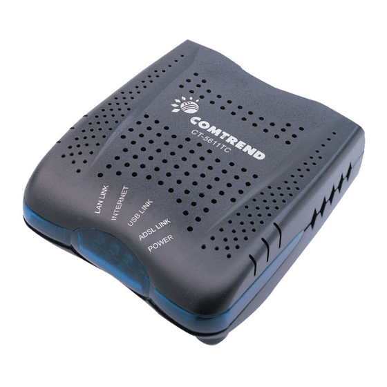
2.2 Front Panel The LED indicators labeled in this top-down view are explained in the table below. Use them to check the status of the device and its connections. Color Mode Function LAN LINK Green An Ethernet Link is established. An Ethernet Link is not established. -
Page 9: Usb Driver Autorun Installation
2.3 USB Driver Autorun Installation Before connecting the CT-5611TC to a PC with USB, the correct drivers must be installed. The auto-run USB driver installation supports Win ME, Win 98, Win 2000, Win XP (32 bit) and Vista (32 bit). For those using Windows XP 64 bit, the driver must be installed manually (please see section 2.3 below for details). - Page 10 STEP 3: When the window displays as below, wait for the drivers to fully install. STEP 4: Click the Finish button, when the window displays as below.
-
Page 11: Usb Driver Manual Installation (64Bit Os)
STEP 5: The installation is complete. You can now connect the device to your PC using a standard USB cable. 2.4 USB Driver Manual Installation (64bit OS) Before connecting this router to a PC with USB, the correct drivers must be installed. - Page 12 STEP 2: When the window displays as below, select Install from a list or specific location (Advanced) and then click the Next button. NOTE: This window won’t display if the USB Driver has been previously installed. In this case, contact technical support for assistance.
- Page 13 STEP 3: Insert the installation CD. NOTE: If you see the autostart menu (as shown in step 1 of previous section) CLICK - and continue with the manual installation process. STEP 4: Select the location of the file using the Browse button, as shown above. Normally, the file is on the CD-ROM shipped with the device.
- Page 14 STEP 5: Locate the Vista folder, and click OK. STEP 6: When the window displays as below, click Next and then wait.
- Page 15 STEP 7: Click the Finish button when the window displays as below.
- Page 16 STEP 8: Installation is complete. You can now use the USB connection.
-
Page 17: Chapter 3 Web User Interface
Chapter 3 Web User Interface This section describes how to access the device via the web user interface (WUI) using an Internet browser such as Internet Explorer (version 5.0 and later). 3.1 Default Settings The following are the default settings for the device: •... - Page 18 STATIC IP Mode To configure the device manually, your PC must have a static IP address within the 192.168.1.x subnet. Follow the steps below to configure your PC IP address to use subnet 192.168.1.x. The following assumes you are running Windows XP. STEP 1: From the Network Connections window, open Local Area Connection (You may also access this screen by double-clicking the Local Area Connection icon on your taskbar).
-
Page 19: Login Procedure
STEP 2: Select Internet Protocol (TCP/IP) and click the Properties button. The screen should now display as below. Change the IP address to the domain of 192.168.1.x (1<x<254) with subnet mask of 255.255.255.0. STEP 3: Click OK to submit the settings. 3.3 Login Procedure Perform the following steps to login to the web user interface. - Page 20 Click OK to continue. NOTE: The login password can be changed later (see 8.6.3 Passwords) STEP 3: After successfully logging in for the first time, you will reach this screen. NOTE1: If a PVC connection already exists then this Quick Setup screen will be bypassed and the Device Info –...
-
Page 21: Chapter 4 Quick Setup
If the service provider provides PPPoE service, then the connection selection depends on whether the LAN-side device (typically a PC) is running a PPPoE client or whether the CT-5611TC is to run the PPPoE client. The CT-5611TC can support both cases simultaneously. -
Page 22: Manual Quick Setup
Step 2: Click Next to start the setup process. Follow the online instructions to complete the setting. This procedure will skip some advanced setup procedures (such as PVC index and encapsulation selection). Step 3: After the settings are complete, you can use the ADSL service. 4.2 Manual Quick Setup STEP 1: Click Quick Setup and un-tick the DSL Auto-connect checkbox to enable manual configuration of the connection type. -
Page 23: Ppp Over Atm (Pppoa) And Ppp Over Ethernet (Pppoe)
STEP 4: Choosing different connection types pops up different encapsulation. Enter appropriate settings as requested by your service provider. The following descriptions state each connection type setup separately. Select Enable 802.1q (by ticking the box) if required, and input a number for the VLAN ID. - Page 24 Choose from AUTO, PAP, CHAP and MSCHAP. Dial on Demand The CT-5611TC can be configured to disconnect if there is no activity for a period of time by selecting the Dial on demand check box. When the checkbox is ticked, you need to enter the inactivity timeout period.
- Page 25 LAN PC. That is, the PC becomes a host belonging to the same IP subnet. • The ADSL router bridges the IP packets between WAN and LAN ports, unless the packet is addressed to the router’s LAN IP address. Use Static IP Address Unless your service provider specially requires this setup, do not select it.
- Page 26 To configure a secondary IP address for the LAN port, click the checkbox below. Step 4: Click Next to display the WAN Setup-Summary screen that presents the entire configuration summary. Click Save/Reboot if the settings are correct. Click Back if you wish to modify the settings.
-
Page 27: Mac Encapsulation Routing (Mer)
The Web UI will not respond until the system is brought up again. After the system is up, the Web UI will refresh to the Device Info screen automatically. The CT-5611TC is ready for operation and the LEDs display as described in the LED description tables. - Page 28 NOTE: The DHCP Client can be enabled for PVC in MER mode if Obtain an IP address automatically is chosen. Changing the default gateway or the DNS effects the whole system. Configuring them with static values will disable the automatic assignment from DHCP or other WAN connection.
- Page 29 Step 3: Upon completion click Next. The following screen appears. The Device Setup screen allows the user to configure the LAN interface IP address and DHCP server. If the user would like this ADSL router to assign dynamic IP addresses, DNS server and default gateway to other LAN devices, select the radio box Enable DHCP server on the LAN to enter the starting IP address and end IP address and DHCP lease time.
-
Page 30: Ip Over Atm
The Web UI will not respond until the system is brought up again. After the system is up, the Web UI will refresh to the Device Info screen automatically. The CT-5611TC is ready for operation and the LEDs display as described in the LED description tables. - Page 31 Step 2: Click Next. The following screen appears. Enable NAT checkbox If the LAN is configured with a private IP address, the user should select this checkbox. The NAT submenu will be displayed on the advanced setup menu after reboot. The user can then configure NAT-related features after the system comes up.
- Page 32 NOTE : Enable DHCP Server Relay will not display if NAT is enabled. The user must configure the IP Address and the Subnet Mask. To use the DHCP service on the LAN, select the Enable DHCP server checkbox, and enter the Start IP addresses, the End IP address and DHCP lease time.
-
Page 33: Bridging
The Web UI will not respond until the system is brought up again. After the system is up, the Web UI will refresh to the Device Info screen automatically. The CT-5611TC is ready for operation and the LEDs display as described in the LED description tables. - Page 34 Step 3: Click Next to continue. The following screen will be displayed. The WAN Setup-Summary screen presents the entire configuration summary. Click Save/Reboot if the settings are correct. Click Back to modify the settings.
-
Page 35: Chapter 5 Device Information
Chapter 5 Device Information This screen provides summary information about the device, ADSL and IP status. NOTE: The selections available on the main menu are based upon account settings and configured connections. -
Page 36: Wan
5.1 WAN Click Device Info on the menu bar to display the WAN option. Then, click WAN on the Device Info menu bar to display the configured PVC(s) and the status. Heading Description VPI/VCI Shows the values of the ATM VPI/VCI Con. -
Page 37: Wan Statistics
Interface Shows connection interfaces Received/Transmitted - Bytes Rx/TX (receive/transmit) packet in bytes - Pkts Rx/TX (receive/transmit) packets - Errs Rx/TX (receive/transmit) packets with errors - Drops Rx/TX (receive/transmit) packets dropped 5.2.2 WAN Statistics The following figure shows the WAN statistics screen. Service WAN service label VPI/VCI... -
Page 38: Atm Statistics
5.2.3 ATM statistics The following figure shows the ATM statistics screen. ATM Interface Statistics Field Description In Octets Number of received octets over the interface Out Octets Number of transmitted octets over the interface In Errors Number of cells dropped due to uncorrectable HEC errors In Unknown Number of received cells discarded during cell header... -
Page 39: Adsl Statistics
a higher layer for transmissions In Errors Number of received AAL5/AAL0 CPCS PDUs received that contain an error. The types of errors counted include CRC- 32 errors. Out Errors Number of received AAL5/AAL0 CPCS PDUs that could be transmitted due to errors. In Discards Number of received AAL5/AAL0 CPCS PDUs discarded due to an input buffer overflow condition. -
Page 41: Route
Field Description Mode Modulation protocol G.dmt, G.lite, T1.413, ADSL2, ADSL2+ Type Channel type Interleave or Fast Line Coding Trellis On/Off Status Lists the status of the DSL link Link Power State Link output power state. SNR Margin (dB) Signal to Noise Ratio (SNR) margin Attenuation (dB) Estimate of average loop attenuation in the downstream direction. -
Page 42: Arp
5.4 ARP Click ARP to display the ARP information. 5.5 DHCP Click DHCP to display the DHCP information. -
Page 43: Chapter 6 Advanced Setup
Chapter 6 Advanced Setup This chapter explains the advanced setup functions available from this submenu. 6.1 WAN Heading Information VPI/VCI ATM VPI (0-255) / VCI (32-65535) Con. ID WAN connection ID number Category ATM service category Service Name of the WAN connection Interface Name of the interface for WAN Protocol... - Page 44 NOTE: NAT is enabled so UPnP is shown above (see underlined notes below). Consult the field descriptions below for more details. IP Address: Enter the IP address for the LAN port. Subnet Mask: Enter the subnet mask for the LAN port. Enable UPnP: Tick the box to enable Universal Plug and Play.
-
Page 45: Nat
IP Address: Enter the secondary IP address for the LAN port. Subnet Mask: Enter the secondary subnet mask for the LAN port. 6.3 NAT To display the NAT function, you must enable the NAT feature in the WAN Setup. 6.3.1 Virtual Servers Virtual Server allows you to direct incoming traffic from WAN side (identified by Protocol and External port) to the Internal server with private IP address on the LAN side. -
Page 46: Port Triggering
Select a Service User should select the service from the list. Custom Server User can enter the name of their choice. Server IP Address Enter the IP address for the server. External Port Start Enter the starting external port number (when you select Custom Server). - Page 47 To add a Trigger Port, click the Add button. The following screen will display. Select an User should select the application from the list. Application User can enter the name of their choice. Custom Application Trigger Port Start Enter the starting trigger port number (when you select custom application).
-
Page 48: Dmz Host
custom application). When an application is selected the port ranges are automatically configured. Open Port End Enter the ending open port number (when you select custom application). When an application is selected the port ranges are automatically configured. Open Protocol User can select from: TCP, TCP/UDP or UDP. -
Page 49: Alg
6.3.4 ALG SIP ALG is Application layer gateway. If the user has an IP phone(SIP) or VoIP gateway(SIP) behind the ADSL router, the SIP ALG can help VoIP packet passthrough the router (NAT enabled). NOTE: SIP (Session Initiation Protocol, RFC3261) is the protocol of choice for most VoIP (Voice over IP) phones to initiate communication. -
Page 50: Security
6.4 Security To display this function, you must enable the firewall feature in WAN Setup. For detailed descriptions with examples please consult Appendix D: Security 6.4.1 IP Filtering IP filtering allows you to create a filter rule to identify outgoing/incoming IP traffic by specifying a new filter name and at least one condition below. - Page 51 Field Description Filter Name Type a name for the filter rule. Protocol User can select from: TCP, TCP/UDP, UDP or ICMP Source IP address Enter source IP address. Source Subnet Mask Enter source subnet mask. Source Port (port or Enter source port number. port:port) Destination IP address Enter destination IP address.
- Page 52 INCOMING IP FILTER To add a filtering rule, click the Add button on the screen below. NOTE: The default setting for Incoming is Blocked. Field Description Filter Name Type a name for the filter rule. Protocol User can select from: TCP, TCP/UDP, UDP or ICMP Source IP address Enter source IP address.
-
Page 53: Mac Filtering
Each network device has a unique 48-bit MAC address. This can be used to filter (block or forward) packets based on the originating device. MAC filtering policy and rules for the CT-5611TC can be set according to the following procedure. The policy FORWARDED means that all MAC layer frames will be FORWARDED except those matching the rules specified in the following table. - Page 54 Field Description Protocol Type PPPoE, IPv4, IPv6, AppleTalk, IPX, NetBEUI, IGMP Destination MAC Address Defines the destination MAC address Source MAC Address Defines the source MAC address Frame Direction Select the incoming/outgoing packet interface WAN Interfaces Applies filter to selected PVCs (bridge mode only). Filter rules are arranged according to PVC, as shown under the VPI/VCI heading on the previous screen.
-
Page 55: Parental Control
6.4.3 Parental Control Parental control allows parents, schools, and libraries to set access times for Internet use. To add a parental control, click the Add button. The following screen will display. Username To set access Internet user name MAC Address To set what MAC to access Internet Days of the week To set what day can be access Internet... -
Page 56: Quality Of Service
6.5 Quality of Service To display the Security function, you must enable QoS in WAN Setup. Choose Add to configure network traffic classes. The following screen will display. Traffic Class Name Enter name for traffic class Assign ATM Transmit Select Low, Medium or High. Priority Mark IP Precedence Select between 1-7. -
Page 57: Routing
Maximize Reliability, Maximize Throughput, Minimize Delay Mark 802.1p if 802.1q is Select between 1-7. The lower the digit shows the enabled on WAN higher the priority Physical LAN Port User can select from: ENET, ENET(1-4), USB or Wireless. Protocol User can select from: TCP, TCP/UDP, UDP or ICMP. Source IP Address Enter the source IP address. -
Page 58: Static Route
6.6.2 Static Route Choose Static Route to display the Static Route screen. The Static Route screen lists the configured static routes, and allows configuring static routes. Choose Add or Remove to configure the static routes. To add static route, click the Add button to display the following screen. Enter the destination network address, subnet mask, gateway AND/OR available WAN interface then click Save/Apply to add the entry to the routing table. -
Page 59: Dns
6.7 DNS 6.7.1 DNS Server If 'Enable Automatic Assigned DNS' checkbox is selected, this router will accept the first received DNS assignment from one of the PPPoA, PPPoE or MER/DHCP enabled PVC(s) during the connection establishment. If the checkbox is not selected, enter the primary and optional secondary DNS server IP addresses. - Page 60 For dynamic DNS service, click the Add button. The following screen will display. D-DNS provider Select a dynamic DNS provider from the list Hostname Enter the name for the dynamic DNS server. Interface Select the interface from the list Username Enter the username for the dynamic DNS server.
-
Page 61: Dsl
6.8 DSL To access the DSL settings, First click On Advanced Setup and then click on DSL. The DSL Settings dialog box allows you to select an appropriate modulation mode. Option Description G.dmt Enabled Sets G.Dmt if you want the system to use G.Dmt mode. G.Lite Enabled Sets G.Lite if you want the system to use G.Lite mode. -
Page 62: Certificate
6.9 Certificate A certificate is a public key, attached with its owner’s information (company name, server name, personal real name, contact e-mail, postal address, etc) and digital signatures. There will be one or more digital signatures attached on the certificate, indicating that these signers have verified that the owner information of this certificate is correct. - Page 63 Certificate Name A user-defined name for the certificate. Common Name Usually, it is the fully qualified domain name for the machine. Organization Name The exact legal name of your organization. Do not abbreviate. State/Province Name The state or province where your organization is located. It cannot be abbreviated.
-
Page 64: Trusted Ca
6.9.2 Trusted CA CA is the abbreviation for Certificate Authority. CA is a part of the X.509 system. It is itself a certificate, attached with the owner information of this certificate authority. But its purpose is not to do encryption/decryption. Its purpose is to sign and issue certificates;... -
Page 66: Chapter 7 Diagnostics
USB connection Down: Indicates that the device does not detect the USB interface on your computer. NOTE: This is not a problem however, since the CT-5611TC does not have a USB port. ADSL Pass: Indicates that the DSL modem has detected a DSL signal Synchronization from the telephone company. - Page 67 Test Condition Ping Primary Pass: Indicates that the device can communicate with the Domain Name primary Domain Name Server (DNS). Server Fail: Indicates that the device was unable to communicate with the primary Domain Name Server (DNS). It may not have an effect on your Internet connectivity.
-
Page 68: Chapter 8 Management
Chapter 8 Management The Management section of the CT-5611TC supports the following maintenance functions and processes: • Settings • System log • SNMP Agent • TR-069 Client • Internet Time • Access Control • Update Software • Save/Reboot 8.1 Settings The Settings option allows you to back up your settings to a file, retrieve the setting file, and restore the settings. -
Page 69: Restore Default
NOTE 1: This entry has the same effect as the hardware reset-to-default button. The CT-5611TC board hardware and the boot loader support the reset to default button. If the reset button is continuously pushed for more than 5 seconds, the boot loader will erase the entire configuration data saved on the flash memory. -
Page 70: System Log
Web UI session be closed and restarted. Before restarting, the connected PC must be configured with a static IP address in the 192.168.1.x subnet in order to configure the CT-5611TC. 8.2 System Log The System Log option under Management>Settings allows you to view the system events log, or to configure the System Log options. - Page 71 The events ranging from the highest critical level “Emergency” down to this configured level will be recorded to the log buffer on the CT-5611TC SDRAM. When the log buffer is full, the newer event will wrap up to the top of the log buffer and overwrite the old event.
-
Page 72: Snmp Agent
8.3 SNMP Agent Simple Network Management Protocol (SNMP) allows a management application to retrieve statistics and status from the SNMP agent in this device. Select the Enable radio button, configure options and click Save/Apply to activate SNMP. 8.4 TR-069 Client WAN Management Protocol (TR-069) allows a Auto-Configuration Server (ACS) to perform auto-configuration, provision, collection, and diagnostics to this device. -
Page 73: Internet Time
used by the CPE for validating the certificate from the ACS when using certificate-based authentication. ACS User Name Username used to authenticate the CPE when making a connection to the ACS using the CPE WAN Management Protocol. This username is used only for HTTP-based authentication of the CPE. -
Page 74: Services
Note: The WAN column is present only if the WAN interface is connected. 8.6.1 Services The Services option limits or opens the access services over the LAN or WAN. These services are provided FTP, HTTP, ICMP, SNMP, SSH (see Appendix C: SSH Client for details), TELNET, and TFTP. -
Page 75: Ip Addresses
8.6.2 IP Addresses The IP Addresses option limits the access by IP address. If the Access Control Mode is enabled, only the allowed IP addresses can access the router. Before you enable it, configure the IP addresses by clicking the Add button. Enter the IP address and click Apply to allow the PC with this IP address managing the DSL Router. -
Page 76: Update Software
8.7 Update Software The Update Software screen allows you to obtain an updated software image file from your ISP. Manual software upgrades from a locally stored file can be performed using the following screen. Step 1: Obtain an updated software image file from your ISP. Step 2: Enter the path to the image file location in the box below or click the Browse button to locate the image file. -
Page 77: Save And Reboot
8.8 Save and Reboot The Save/Reboot option saves the configurations and reboots the router. Close the DSL Router Configuration window and wait for 2 minutes before reopening your web browser. If necessary, reconfigure your PC's IP address to match your new configuration. -
Page 78: Appendix A: Pin Assignments
Appendix A: Pin Assignments Line port (RJ11) Definition Definition ADSL_TIP ADSL_RING LAN Port (RJ45) Definition Definition Transmit data+ Transmit data- Receive data- Receive data+... -
Page 79: Appendix B: Specifications
Appendix B: Specifications Hardware Interface RJ-11 X1 for ADSL2+, RJ-45 X 1 for LAN, mini-USB X 1 for LAN, Reset Button X 1, Power switch X 1 WAN Interface Standard: ITU-T G.992.5, ITU-T G.992.3, ITU-T G.992.1, ANSI T1.413 Issue 2 G.992.5 (ADSL2+) ..Downstream : 24 Mbps Upstream : 1.3 Mbps G.992.3 (ADSL2)...Downstream : 12 Mbps Upstream : 1.3 Mbps G.DMT ......Downstream:... - Page 80 Operating temperature ......0 ~ 50 degrees Celsius Relative humidity ........5 ~ 95% (non-condensing) Dimensions 152 mm (W) x 28 mm (H) x 112 mm (D) Kit Weight = 0.65 kg (1*CT-5611TC,1*RJ11 cable,1*USB cable,1*RJ45 cable,1*Power Adapter, *CD-ROM) NOTE: Specifications are subject to change without notice...
-
Page 81: Appendix C: Ssh Client
Appendix C: SSH Client Linux OS has a ssh (Security Socket Share) client included. Although Microsoft Windows does not have a ssh client, there is a public domain one called “putty” that can be downloaded from here: http://www.chiark.greenend.org.uk/~sgtatham/putty/download.html To access the ssh client you must first enable SSH access for LAN or WAN from the Management Access Control Services menu in the web user interface. -
Page 82: Appendix D: Security
Appendix D: Security Stateful Packet Inspection Refers to an architecture, where the firewall keeps track of packets on each connection traversing all its interfaces and makes sure they are valid. This is in contrast to static packet filtering which only examines a packet based on the information in the packet header. - Page 83 Example 2: Filter Name : Out_Filter2 Protocol : UDP Source Address : 192.168.1.45 Source Subnet Mask : 255.255.255.0 Source Port : 5060:6060 Destination Address : 172.16.13.4 Destination Subnet Mask : 255.255.255.0 Destination Port : 6060:7070 This filter will drop all UDP packets coming from LAN with IP Address/ Subnet Mask 192.168.1.45/24 and a source port in the range of 5060 to 6060, destined to 172.16.13.4/24 and a destination port in the range of 6060 to 7070.
- Page 84 source port of 80 irrespective of the destination. All other incoming packets on this interface are DROPPED. Example 2: Filter Name : In_Filter2 Protocol : UDP Source Address : 210.168.219.45 Source Subnet Mask : 255.255.0.0 Source Port : 5060:6060 Destination Address : 192.168.1.45 Destination Subnet Mask : 255.255.255.0...
- Page 85 Addition of this rule drops all PPPoE frames going from LAN-side to WAN-side with a Destination MAC Address of 00:12:34:56:78:90 irrespective of its Source MAC Address on the br_0_34 WAN interface. All other frames on this interface are forwarded. Example 2: Global Policy: Blocked Protocol Type: PPPoE Destination MAC Addr: 00:12:34:56:78:90...
Need help?
Do you have a question about the CT-5611TC and is the answer not in the manual?
Questions and answers