Table of Contents
Advertisement
Advertisement
Table of Contents

Related Manuals for Comtrend Corporation CT-520


Summary of Contents for Comtrend Corporation CT-520
- Page 1 CT-520 SHDSL Router User’s Manual Version A5.2, 5-15-2002 260014-013...
- Page 3 This manual is written for software version 2.48. It is designed to provide information to network administrators. It covers the installation, operation and applications of the CT-520 SHDSL router. Version History The manual has been updated from version 2.44., and includes the addition of Configuring Transparent Bridging (Section 6.6).
- Page 4 Copyright Copyright© 2002 Comtrend Corporation. All rights reserved. The content of this manual is subject to change without notice. The information and messages contained herein are proprietary to Comtrend Corporation. No part of this manual may be translated, transcribed, reproduced, in any form, or by any means without prior written permission by Comtrend Corporation.
-
Page 5: Table Of Contents
Part I: Getting Started..........1 Chapter 1 Introduction ................3 Overview..................3 Features ..................4 Application ................... 5 Front Panel LED Indicators .............. 6 Chapter 2 Installation ................7 Rear Panel Connectors ..............7 Preparing for Installation ..............7 Installation Procedures ..............8 Chapter 3 Accessing the Router ..............9 Access by Console ................. - Page 6 Forwarding Table ................41 Configuring transparent bridging ............41 Chapter 7 IP Routing ................43 RIP Configuration .................43 Advanced RIP Configuration ............43 Static Route Configuration .............45 7.3.1 Add a static route .................45 7.3.2 Delete a Static Route ..............45 7.3.3 Routing Table/ List Static Routes.............46 Ping Test Utility ................46 Chapter 8 Network Address Translation..........47...
- Page 7 12.3 Configuration Backup and Restoration ..........89 12.3.1 Configuration Backup ..............89 12.3.2 Configuration Restoration ..............90 12.4 Upgrading the Homepage ..............91 12.5 Performance Monitoring..............92 12.5.1 SHDSL Status Monitor ..............92 12.5.2 ATM Interface Monitor ..............92 12.5.3 SHDSL Performance Statistics ............93 12.5.4 Interface Performance Monitor ............93 12.6 Utilities ..................94 12.6.1 TFTP Application................94...
-
Page 9: Part I: Getting Started
Part I: Getting Started This section will provide an overview of the CT-520, including its features, and applications. Then, it will provide information for hardware installation, access to the router, and initial configuration of the router. For most users this section will provide sufficient information to setup and operate your router. -
Page 11: Chapter 1 Introduction
Chapter 1 Introduction Overview The CT-520 SHDSL router satisfies the needs of multiple users for small office / home office and remote office / branch office applications. It provides a symmetrical transmission speed up to 2.3 Mbps through SHDSL connection over one ordinary telephone line. -
Page 12: Features
Features The router has the following features. Compact and high-performance standalone unit Bridge function Comply with ITU-T G.991.2 (G.shdsl) Auto-negotiation rate adaptation AAL5 for ATM over SHDSL UBR/CBR/VBR ATM services VC-based and LLC multiplexing Up to 16 VCs One Ethernet port for LAN connection One console port for local management Embedded SNMP agent Web-based management... -
Page 13: Application
Application The CT-520 can be applied for DSLAM and point-to-point applications. Figure 1-1 DSLAM Application Figure 1-2 Point-to-point Application... -
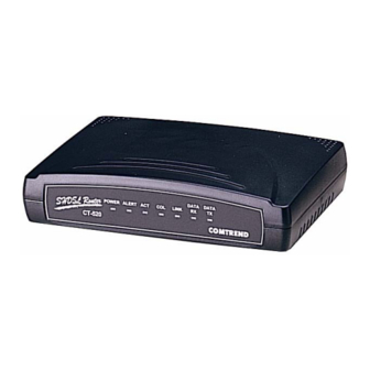
Page 14: Front Panel Led Indicators
The description of each LED is given in Table 1-1. DATA DATA POWER ALERT LINK CT-520 Figure 1-3 Front View Color Mode Function POWER Green 12VAC power input is supplied to this unit... -
Page 15: Chapter 2 Installation
Chapter 2 Installation Rear Panel Connectors There are four connectors on the rear panel. To make a connection with these connectors, refer to Section.2.3. Preparing for Installation Make sure the following equipment is ready before installing the router. VT-100 Compatible Terminal – This terminal is essential to perform the initial configuration of the router. -
Page 16: Installation Procedures
Installation Procedures Figure 2-1 illustrates possible connections to the backplane connectors. Figure 2-1 Installation Step 1 Connect the Line port to the phone line. Step 2 Connect the LAN port to a hub with a straight-through RJ45 cable, or connect the router to a PC with a crossover RJ45 cable. Step 3 Connect the Console port to the VT-100 compatible terminal with a RS232 straight-through cable for local management. -
Page 17: Chapter 3 Accessing The Router
Chapter 3 Accessing the Router This chapter introduces how to access and manage the router. Initial configuration of the router is covered in Chapter 4, Initial Configuration. There are three methods to access the router: console, Telnet, and Web. Any of the methods can be used to access, configure, operate or monitor the router. - Page 18 Step 4 Use the up/down-arrow keys to select the utility item you want and then use the right-arrow key to enter the menu you will configure. Note: To configure the router for Telnet and Web access, complete the procedures below to change the necessary parameters. If you do not require Telnet or Web access you can go directly to step 13, in which case you will be using the following default values: LAN IP address: 210.65.231.206...
-
Page 19: Access By Telnet
Access by Telnet The device permits a maximum of one ADMINISTRATOR, and two COMMON users to telnet to the system at the same time. The following steps show the configuration. Step 1: Telnet to the router with the LAN IP address or WAN IP address [refer to Section 3.1, Steps 6 and 7 on setting the LAN/WAN IP addresses]. -
Page 20: Access By Web
Access by Web Only one person at a time can gain access to the router from the Web. The following steps show the configuration for Web-based access. Step 1: Browse the router with the LAN IP address or WAN IP address [refer to Section 3.1 Steps 6 and 7 on setting the LAN/WAN IP address]. -
Page 21: Keyboard Operations
Keyboard Operations ↑ The upward arrow key moves the cursor upward in the menu ↓ The cursor moves downward in the menu. ← Returns to the previous menu. If you are in a leaf menu you may need to push first (to save the information) →... -
Page 22: Menu Layout
Menu Layout The operating menu of the router follows a tree-structured design with three categories: main menu, branch menu and leaf menu. You can select each menu item by using the up, down, left and right arrow keys in the main and branch menus. -
Page 23: Configuration Steps In Console/Telnet
Configuration Steps in Console/Telnet This section will briefly explain the steps involved to configure your router from the console or from Telnet. For ease of use, when describing configuration procedures in this document, the full path name is given, e.g.,> MAIN/QC/LAN. For example, if you want to configure the LAN interface of the router, complete the following procedures. - Page 24 Step 2: Use the up or down arrow keys to select an item. In this case, select QC. Press the right arrow key to go to the MAIN/QC menu. The text at the bottom-left of the screen, should read: PATH> MAIN/QC to indicate the directory of the current operating menu.
-
Page 25: Write System Configurations
Step 5: Return to the main menu and enter the MAIN\WRITE menu to save the configurations from RAM to flash memory, and then reboot the device. Note: Before you exit the Console or Telnet session, make sure you write the changes into the flash memory and reboot the router. -
Page 26: Reboot System
3.6.2 Reboot System To reboot the device, follow the steps below: Step 1: Enter the MAIN/REBOOT menu, the following message will be displayed: This will reboot the system? (Y/N). Step 2: Type Y to reboot the system. Step 3: Wait for the message: Press ESC to enter console mode configuration... -
Page 27: Initial Configuration (Console/Telnet)
Chapter 4 Initial Configuration (Console/Telnet) This chapter explains initial configuration, quick configuration and SHDSL characteristics parameters. For further configuration of the specific functions, refer to Chapters 6 to 11. Initial Setup For the initial setup of your router, please complete the following steps: Step 1: Enter the MAIN/CONF/SYSTEM menu Step 2: Complete the fields below: Field... -
Page 28: Quick Configuration
Step 3: Press Ctrl-S to save the configuration to the system RAM Step 4: If you want to keep the configuration permanently, perform the Write function by entering the MAIN/WRITE menu and then reboot the router. You only need to perform this function before you exit your configuration software, if you will continue to configure your router you can perform the write function later. -
Page 29: Atm Interface
4.2.2 ATM Interface The ATM interface field defines the data encapsulation and protocol characteristics for the connection between two packet switching devices. The router supports PPP and RFC 1483 routing protocols. For PPP network service, the router supports two authentication protocols: PAP, and CHAP. It can identify the server’s authentication protocol and will auto-adjust itself to the same protocol. - Page 30 Step 3: Enter a parameter in each field Enable or disable the ATM interface Interface: Protocol: Ethernet: RFC1483 Bridge (default), can be selected in router or bridge mode The following only operate in router mode: (see section 4.1) PPP (PPP over ATM) PPPOE (PPP Over Ethernet): When running either PPP or PPPOE, the user may have to configure the following:...
-
Page 31: Atm Virtual Channel (Vc) Parameters
Step 4: Hold down the Ctrl-S keys to save the new configurations to your system 4.2.3 ATM Virtual Channel (VC) Parameters You may need to define virtual connections (VC) when communicating across an ATM network. There are two types of ATM connections: Virtual paths, identified by virtual path identifiers (VPI) Virtual circuits, identified by the combination of a VPI and a VCI (virtual circuit identifier) - Page 32 The Peak Cell Rate is the maximum number of bits per second Peak Cell Rate (bps): transmitted over this connection. This is determined by the minimum intercellular space, in seconds, which is the time interval from the first bit of one cell to the first bit of the next cell.
-
Page 33: Isp Configuration
4.2.4 ISP Configuration The ISP (Internet service provider) should be configured when PPP/PPPOE is selected. The router can be connected to up to eight ISPs, each with different VPI/VCI values. The procedure below shows how to configure the necessary parameters to connect to an ISP. Please note, this function can only be performed when your device is set to router mode [see Section 4.1]. -
Page 34: Shdsl Characteristics Parameters
SHDSL Characteristics Parameters In the MAIN/CONF/SHDSL menu, you can set up the system chipset characteristics. Field Parameter Description Minimum Base Nx64 Kbps You can set a fixed data rate when the Rate(1-36) (N=1-36) following two conditions are matched: 1. Maximum subrate is set equal to the Maximum Base Nx64 Kbps minimum subrate 2. -
Page 35: Chapter 5 Web Based Configuration
Chapter 5 Web Based Configuration This chapter describes how to manage the router via the Web browser from the remote end. The Web page is best read with a display resolution of 1024 x 768 or 800 x 600. To change the resolution you can go to the Microsoft Windows control panel and click on the Display icon, and change the display settings. -
Page 36: Web
Step 4: After successfully logging in, you will reach the main configuration page. Figure 5-1 Web Main Menu Web page layout On each Web page, there are three basic areas. The first is the top panel of the Web page, with the following buttons: Button Destination Home:... - Page 37 2. The second is the sub-menu located on the left side that changes after the operator clicks a button in the top panel described above. 3. The third is the main window in middle of the page, which is the area that displays the parameters or explanations of the sub-menus.
-
Page 38: Operation
Operation The Web page follows a tree-structured design. The operational methods are similar to the console and Telnet modes. A systematic method is used to configure the router. On-screen explanations of each function or parameter are provided to help the operator to know what is being done and what can be processed next. -
Page 39: Quick Setup
Quick Setup The Quick Setup Wizard includes five steps. The router can normally function after these steps are completed. The Setup button links to a quick configuration page for the administrator to easily customize the router. It has the following functions: LAN Parameters ATM Interface Parameters... -
Page 40: Basic Configuration
Basic Configuration At this stage, the administrator can alter the following parameters: Load Factory Default System Parameters (host name, domain name, operation mode, SHDSL physical mode, user password) ISP Parameters (router mode only) ATM VC Parameters ATM Interface Parameters DHCP Parameters (router mode only) NAT Parameters (router mode only) Review Parameters Save and Restart... -
Page 41: Advance Configuration
Step 4: Click the Finish button to confirm the settings. Step 5: The system will prompt the administrator to save (write) the configurations into the system flash memory and then restart the system to make the new parameters effective. Click the Save button and then the Restart button as instructed. -
Page 42: Utilities
Step 2: Follow the online explanations to configure each function. Step 3: After the parameters are set up, the page will display all the adjusted settings for the administrator to review the settings. Step 4: Click the Finish button to confirm the settings. Step 5: The system will ask the administrator to save (write) the configurations into the system flash memory and then restart the... -
Page 43: Monitor
Monitor On the Monitor page, you can perform the following functions: System information (System Name, Firmware Version, Hardware Information, System Time) SHDSL Status Monitor ATM Interface Monitor SHDSL Performance Statistics Line Attenuation and Noise Margin CRC/ES/SES/LOSWS/UAS Interface Performance Statistics Transmitted and Received Packets Transmitted and Received Rates Interface Performance Statistics Transmitted and Received Packets... -
Page 45: Part Ii: Advanced Configuration
Part II: Advanced Configuration This section will explain how to configure the advanced parameters of the CT-520. Chapter 6: Bridging Chapter 7: IP Routing Chapter 8: Network/Port Address Translation Chapter 9: DNS Proxy Chapter 10: DHCP Chapter 11: SNMP... -
Page 47: Chapter 6 Bridging
Bridging Overview The CT-520 can be set to bridge or router mode. A bridge is a device that links local or remote area networks together. It forwards packets based on a MAC address. A router links networks, it forwards packets based on an IP address. It can be used to separate unwanted traffic, reduce the traffic, or to provide security from unauthorized users. -
Page 48: Delete Static Mac Address
Delete Static MAC Address Step 1 Enter the MAIN/CONF/BRIDGING/DELETE menu. Step 2 Enter the MAC address. Step 3 Hold down the Ctrl-S keys to delete the MAC address. Spanning Tree Protocol The spanning can be used to avoid errors in data flow. The default setting of the Spanning Tree Protocol (STP) function of the router is disabled. -
Page 49: Forwarding Table
Forwarding Table To list the bridging table where you can find the network status, enter the MAIN/UTIL/BRIDGING menu. Configuring transparent bridging Transparent bridging provides integrated routing and bridging, which enables routing of a protocol between routed interfaces and bridge groups. This feature can be set to on a LAN interface (see section 4.2.1) or an ATM interface (see section 4.2.2). -
Page 51: Chapter 7 Ip Routing
Chapter 7 IP Routing This chapter covers RIP configuration, static routing, and ping test functions. RIP Configuration The IP routing function is disabled by factory default. To enable this function, enter the MAIN/CONF/SYSTEM menu, and select Router in the Operation Mode field (also described in Section 4.1). - Page 52 Enabled: to enable the Poison Reverse Disabled: to enable the Splitting Horizon The default setting of poison reverse parameter in CT-520 is Enabled. It means the router adopts the split horizon with poison reverse scheme to avoid routing loop problems. If the parameter is disabled, the router will use the simple split horizon scheme to solve the problem.
-
Page 53: Static Route Configuration
Static Route Configuration This section explains how to add, delete and verify a static route. 7.3.1 Add a static route Step 1: Enter the MAIN/CONF/ROUTING/STATIC/ADD menu Step 2: Enter a parameter in each field (Note: The default route for the network/host address and subnet mask is 0.0.0.0.) Network/Host Enter the network or host address of the destination... -
Page 54: Routing Table/ List Static Routes
7.3.3 Routing Table/ List Static Routes In order to validate the RIP configuration for each interface, the router provides a utility function to view the routing table located in the MAIN/UTIL/ROUTING menu. You can view the configuration of static routes at: MAIN/CONF/ROUTING/STATIC/LIST Ping Test Utility The Ping test is used to verify the status of the network connection after the RIP or... -
Page 55: Chapter 8 Network Address Translation
Chapter 8 Network Address Translation This Chapter is divided into the following sections: Overview of Network Address Translation (NAT) Network Address Translation Port Address Translation Configuration of NAT/PAT Applications for NAT/PAT Overview Network Address Translation (NAT) is a transparent routing function that translates a Private IP address on a LAN into a Public address that can be used in a public network (Figure 8-1). -
Page 56: Network Address Translation
Network Address Translation Network Address Translation (NAT) is a transparent routing function that translates a Private IP address on a LAN, into a Public address that can be used on a WAN. Static NAT defines a fixed address translation. A Private IP address is mapped to a Public IP address on a one-to-one basis. - Page 57 the number of public addresses restricts the number of simultaneous connections. PAT [Section 8.3] should be used if the number of connections required, will exceed the number of Public Addresses. (2). The ATM interface IP address presents the management address of the SHDSL Router.
-
Page 58: Port Address Translation
Port Address Translation PAT, also called overloading is a form of NAT that maps multiple Private IP addresses to a single Public IP address. PAT allows several virtually addressed workstations to share a single global address. PAT uses the TCP and UDP port numbers to map multiple virtual addresses to a single global address. - Page 59 The conventions of PAT mode: (1). The global pool is permitted to overlap the ATM interface IP address (2). PPTP pass through is supported (3). The ATM interface IP address presents the management address of the SHDSL Router. This IP address is available for ping, telnet and Web management from the Internet.
-
Page 60: Bi-Directional Nat (Two-Way Nat)
8.3.1 Bi-directional NAT (Two-Way NAT) Traditional NAT allows hosts within a private network to transparently access hosts in the external network, in a traditional NAT, sessions are uni-directional, outbound from the private network. With bi-directional NAT, sessions can be initiated from hosts in the public network or in the private network. -
Page 61: Configuration Of Nat/Pat
Operation Mode: Select route Enable the ATM interface Interface: Network Type: Set to Global to enable inbound NAT, set to Virtual to enable outbound NAT [see section 8.3.1 for details] Refer to Section 4.2.3 of the CT 520 manual for all other parameters. Step 4: Hold down the Ctrl-S keys to save the new configurations to your system RAM (if you wish to make the new settings permanent you should write the settings... -
Page 62: Set Routing Mode
8.4.1 Set Routing Mode To set the SHDSL Router to routing mode complete the following steps: Step 1 Enter > MAIN/CONF/SYSTEM Step 2 In the Operation Mode field, select Route Step 3 Hold down the Ctrl-S keys. 8.4.2 Configure the LAN Interface Step 1 Enter >... -
Page 63: Assign Private Ip Address Pools
Step 3 In the Interface Type field, select Enabled Step 4 In the Network Type field, select Global for a traditional outbound NAT, or Virtual for an inbound NAT using bi-directional NAT [See Section 8.3.1] Step 5 Hold down the Ctrl-S keys 8.4.4 Assign Private IP address Pools This section explains how to configure private IP address pools. -
Page 64: Assign Global Ip Address Pools
8.4.5 Assign Global IP Address Pools The router allows up to five sets of continuous global IP addresses. The private IP pools will be translated to one of the global IP addresses pools, configure as follows: Step 1: Enter the MAIN/CONF/NAT/GLOBAL menu. Step 2: Enter the following parameters. -
Page 65: Fixed Ip Address Mapping
Delete A NAT Pool Translation Step 1: Enter MAIN/CONF/NAT/TRANSLATION/DELETE Step 2: Enter a parameter in each field Private IP Pool: Press the Tab key to select a private pool number Global IP Pool: Press the Tab key to select a global pool number Translation Type: Press the Tab key to select a type: NAT or PAT Step 3: Hold down the Ctrl-S keys to update the settings List NAT Pool Translation... -
Page 66: Configure Virtual Servers
Delete a Fixed IP Address Mapping Step 1: Enter the MAIN/CONF/NAT/FIXED/DELETE menu. Step 2: Enter a parameter in each field. Private IP Address Public IP Address Step 3: Hold down the Ctrl-S keys to delete the mapping. List Fixed IP Mappings To display the Fixed IP Maps, enter the MAIN/CONF/NAT/FIXED/LIST menu. - Page 67 (default: ANY) If ANY is selected, any of the interfaces can Interface: access the service. If you want to specify the interface through which the server provides service, you can select LAN, or ATM1 through to ATM16 Service Name: This field is used to recognize the service that the virtual server provides.
-
Page 69: Configure Static Routes
8.4.9 Configure Static Routes A static route is a permanent entry in a routing table that takes precedence over routes chosen by dynamic routing protocols. To add a static route complete the following steps: Step 1: Enter MAIN/CONF/ROUTING/STATIC/ADD Step 2: Enter a parameter in each field. Note: The default route for the network/host address and subnet mask is 0.0.0.0. -
Page 70: Applications
Routing Table/ List Static Routes In order to validate the RIP configuration for each interface, the router provides a utility function to view the routing table located in the MAIN/UTIL/ROUTING menu. You can view the configuration of static routes at: MAIN/CONF/ROUTING/STATIC/LIST Applications This section will explain the following applications for address translations:... - Page 71 STEP 1 Ensure the SHDSL Router is operating in routing mode by entering MAIN/CONF/SYSTEM, and selecting Router in the Operation Mode; selecting CPE in the Terminal Type. To save the parameters press ctrl-s. STEP 2 Setup the Lan parameters by entering MAIN/CONF/INTERFACE/LAN, set the Network Type to Virtual, and enter the IP Address and Subnet Mask for the LAN.
- Page 72 STEP 3 Setup ATM Interface 1 from the MAIN/CONF/INTERFACE/ATM/ATM1 menu, set the Protocol to IPOA, enter the IP Address and Subnet Mask for ATM Interface 1. To save the parameters press ctrl-s. STEP 4 Add the first Fixed IP Mapping by entering MAIN/CONF/NAT/FIXED/ADD, enter the Private IP Address and the Global IP Address.
- Page 73 STEP 5 Add the second Fixed IP Mapping by entering MAIN/CONF/NAT/FIXED/ADD, enter the Private IP Address and the Global IP Address. To save the parameters press ctrl-s. STEP 6 You can check you have set the correct parameters for the mappings by entering MAIN/CONF/NAT/FIXED/LIST...
-
Page 74: Dynamic One-To-One Nat
STEP 7 To add the static route enter MAIN/CONF/ROUTING/STATIC/ADD, enter values for the Network/Host Address, Subnet Mask, Gateway Address and the Metric [Section 8.4.9]. To save the parameters press ctrl-s. Note that a Network Address of 0.0.0.0 and a Subnet Mask of 0.0.0.0, corresponds to the default route (everything is routed). - Page 75 STEP 1 Ensure the SHDSL Router is operating in routing mode by entering MAIN/CONF/SYSTEM, and selecting Router in the Operation Mode; selecting CPE in the Terminal Type. To save the parameters press ctrl-s. STEP 2 Setup the Lan parameters by entering MAIN/CONF/INTERFACE/LAN, set the Network Type to Virtual, and enter the IP Address and Subnet Mask for the LAN.
- Page 76 STEP 3 Setup ATM Interface 1 from the MAIN/CONF/INTERFACE/ATM/ATM1 menu, set the Protocol to IPOA, enter the IP Address and Subnet Mask for ATM Interface 1. To save the parameters press ctrl-s. STEP 4 To setup the Virtual IP Address pool enter MAIN/CONF/NAT/PRIVATE, select pool 1 in the Pool Number field, and enter the Start IP Address and the End IP Address.
- Page 77 STEP 5 Setup the Global IP Address Pool by entering MAIN/CONF/NAT/GLOBAL, select Pool 1 in the Pool Number field, enter the Start IP Address and the End IP Address. To save the parameters press ctrl-s. STEP 6 To add a NAT Pool Translation enter MAIN/CONF/NAT/TRANSLATION/ADD, select pool 1 in the Private IP Pool field, select Pool 1 in the Global IP Pool field, and select NAT in the Translation Type field.
-
Page 78: Dynamic Many-To-One Pat
STEP 7 To add the static route enter MAIN/CONF/ROUTING/STATIC/ADD, enter values for the Network/Host Address, Subnet Mask, Gateway Address and the Metric. A metric is a standard of measurement, such as path length, that is used by routing algorithms to determine the optimal path to a destination. To save the parameters press ctrl-s. - Page 79 STEP 1 Ensure the SHDSL Router is operating in routing mode by entering MAIN/CONF/SYSTEM, and selecting Router in the Operation Mode; selecting CPE in the Terminal Type. To save the parameters press ctrl-s. STEP 2 Setup the Lan parameters by entering MAIN/CONF/INTERFACE/LAN, set the Network Type to Virtual, and enter the IP Address and Subnet Mask for the LAN.
- Page 80 STEP 3 Setup ATM Interface 1 from the MAIN/CONF/INTERFACE/ATM/ATM1 menu, set the Protocol to IPOA, enter the IP Address and Subnet Mask for ATM Interface 1. To save the parameters press ctrl-s. STEP 4 To add the static route enter MAIN/CONF/ROUTING/STATIC/ADD, enter values for the Network/Host Address, Subnet Mask, Gateway Address and the Metric.
-
Page 81: Dynamic Many-To-Many Pat
8.5.4 Dynamic Many-to-Many PAT STEP 1 Ensure the SHDSL Router is operating in routing mode by entering MAIN/CONF/SYSTEM, and selecting Router in the Operation Mode; selecting CPE in the Terminal Type. To save the parameters press ctrl-s. - Page 82 STEP 2 Setup the Lan parameters by entering MAIN/CONF/INTERFACE/LAN, set the Network Type to Virtual, and enter the IP Address and Subnet Mask for the LAN. To save the parameters press ctrl-s. STEP 3 Setup ATM Interface 1 from the MAIN/CONF/INTERFACE/ATM/ATM1 menu, set the Protocol to IPOA, enter the IP Address and Subnet Mask for ATM Interface 1.
- Page 83 STEP 4 Setup the Virtual IP Address Pool by entering MAIN/CONF/NAT/PRIVATE, select Pool 1 in the Pool Number field, enter the Start IP Address and the End IP Address. To save the parameters press ctrl-s. STEP 5 Setup the Global IP Address Pool by entering MAIN/CONF/NAT/GLOBAL, select Pool 1 in the Pool Number field, enter the Start IP Address and the End IP Address.
- Page 84 STEP 6 To add a NAT Pool Translation by enter MAIN/CONF/NAT/TRANSLATION/ADD, select pool 1 in the Private IP Pool field, select Pool 1 in the Global IP Pool field, and select NAT in the Translation Type field. To save the parameters press ctrl-s. STEP 7 To add the static route enter MAIN/CONF/ROUTING/STATIC/ADD, enter values for the Network/Host Address, Subnet Mask, Gateway Address and the Metric.
-
Page 85: Virtual Server Mapping
8.5.5 Virtual Server Mapping To add a virtual server, enter MAIN/CONF/NAT/SERVER/ADD, enter the parameters in the fields as in the picture below: To save the parameters press ctrl-s. Note that the Interface should be set to ANY to allow all interfaces to access the server [see section 8.4.8 for details about other settings]. -
Page 87: Chapter 9 Dns Proxy
Chapter 9 DNS Proxy Overview A Domain Name Server (DNS) provides an IP address to a host computer for an applied Domain Name. The router supports the DNS proxy feature, which receives and attempts to find an entry in its local tables, and when one is not found, it forwards the request to a remote server. -
Page 89: Chapter 10 Dhcp
Chapter 10 DHCP 10.1 Overview The Dynamic Host Configuration Protocol (DHCP) provides a centralized approach to assigning IP address. When a workstation is configured for automatic IP address assignment, it broadcasts a request to the LAN. The router acts as the DHCP Server and responds with: An IP address and subnet mask for the workstation The Domain name, which is the same as that in MAIN/CONF/SYSTEM... -
Page 91: Chapter 11 Snmp
Chapter 11 SNMP The router supports SNMP (Simple Network Management Protocol) management. MIBs of MIB II are implemented. This chapter describes how to set the SNMP community [Section 11.1], and trap destinations [Section 11.2]. 11.1 Community Step 1: Enter MAIN/CONF/SNMP/COMMUNITY menu. Step 2: Enter a parameter in each field. -
Page 92: Delete Trap Destination Entry
11.2.2 Delete Trap Destination Entry Step 1: Enter the MAIN/CONF/SNMP/TRAP menu Step 2: Enter the following parameters Version: Version 1/Version 2 Enter the destination IP address Destination IP: Enter the parameter for the community Community: Step 3: Hold down the Ctrl-S keys to delete the trap destination entry. 11.2.3 List Trap Destination Entries To list the trap destination entries, access the MAIN/CONF/SNMP/TRAP/LIST menu. -
Page 93: Part Iii: Maintenance And Applications
Part III: Maintenance and Applications This section will discuss maintenance of your CT-520 including updating software/firmware and restoring default settings. It will also show some of the applications and typical setups for the device. Finally, some solutions will be given to some common areas of difficulty in the troubleshooting section. -
Page 95: Chapter 12 Maintenance
Chapter 12 Maintenance 12.1 Load Factory Default Values Step 1: Enter the MAIN/CONF/DEFAULT menu. Step 2: You will see the following message: This will set system parameters to factory default!(Y/N) Step 3: Press the Y key. The system will proceed to restore the default configurations. -
Page 96: Software Upgrade
12.2 Software Upgrade The router utilizes the TFTP protocol to upgrade the router software. Follow the steps below to upgrade the router software. Step 1: Enter the MAIN/UTIL/TFTP menu Step 2: Enter a parameter in the following fields TFTP Server IP Address: Enter the TFTP Server IP address File Name: Enter the file name of the software TFTP option:... -
Page 97: Configuration Backup And Restoration
12.3 Configuration Backup and Restoration The router utilizes the TFTP protocol to back up and restore the current configuration parameters. The administrator may save the configuration parameters as a file and retrieve it later. To do this, you need to set up a TFTP server, which can be LAN-connected or WAN-connected to the router. -
Page 98: Configuration Restoration
12.3.2 Configuration Restoration To retrieve configuration parameters, saved in a previous backup session [see Section 11.3.1] follow the steps below: Step 1: Start from the MAIN/UTIL/TFTP menu Step 2: Enter a parameter in the following fields: TFTP Server IP Address: Enter the TFTP Server IP address Enter the file name for the configuration file File Name:... -
Page 99: Upgrading The Homepage
12.4 Upgrading the Homepage The homepage image file is pre-downloaded in the system by factory default. Follow the steps below to upgrade it. Step 1: Enter the MAIN/UTIL/TFTP menu. Enter the TFTP Server IP address TFTP Server IP Address: File Name: Enter the file name of the homepage TFTP option: Choose Download... -
Page 100: Performance Monitoring
12.5 Performance Monitoring Enter the MAIN/MON menu. You can monitor the following interface statuses. SHDSL Status Monitor ATM Interface Monitor SHDSL Performance Statistics Interface Performance Statistics 12.5.1 SHDSL Status Monitor You can view the SHDSL status from the MAIN/MON/STATUS menu. The following information is provided: Terminal Type: CO or CPE Operate State:... -
Page 101: Shdsl Performance Statistics
12.5.3 SHDSL Performance Statistics You can monitor the SHDSL line performance from the MAIN/MON/SHDSLPERF menu. In the menu, the statistics of the SHDSL line performance are recorded. You can reset the items marked since reset by holding down the Ctrl-T keys. Line Attenuation (dB): Current attenuation Signal-to-Noise Ratio (dB) CRC (since reset): The cumulative statistics of seconds, since last reset,... -
Page 102: Utilities
TxPkts (since reset): the transmitted packets, since last reset RxPkts (since reset): the received packets, since last reset Discards (since reset): the received packets that are discarded since last reset RxErrors (since reset): the received errors, since last reset. The errors may be ATM interface errors (HEC error, ABORT error, Receive Length error, CRC error, Receive Frame Length Violation, Receive nonoctect-aligned frame, Short Frame, CRC error, Overrun, and Collision),... -
Page 103: Ping Test
12.6.2 Ping Test Located at MAIN/UTIL/PING this test is used to verify the accessibility of a host or other device by sending it a message and monitoring the response. Input the IP address of the device you wish to access Host IP Address Data Size(bytes) Enter the data size in bytes that you wish to send... -
Page 104: Eoc Diagnostics
Digital Loopback Test This test is a local digital loopback test that connects the device’s receiver output back to the transmitter input. This test disrupts the transmission of primary data. Spectrum Test This tests the power of the frequency spectrum. This requires external equipment such as a spectrum analyser or a true RMS voltmeter. -
Page 105: Chapter 13 Applications
Chapter 13 Applications This chapter describes the possible applications of the device and the configuration procedures of these applications. 13.1 Example 1: Point to DSLAM Application If the device is used for point to DLSAM application, complete the following procedure. Step 1 Enter the MAIN/CONF/SYSTEM menu and configure the operation mode and terminal type. - Page 106 Interface and Protocol fields. If the interface you want to configure is disabled, you must enable it first from the Interface field. The Protocol field of the CT-520 has several options: Ethernet, PPP, IP Over ATM, and PPPoE. When you configure this field, make sure both devices support the same protocol and use the same ATM interface.
-
Page 107: Example 2: Point To Point Application
13.2 Example 2: Point to Point Application If two devices are used for point-to-point application, follow the procedure below to set up both devices. Step 1 Enter the MAIN/CONF/SYSTEM menu and configure the operation mode and terminal type. In this case, select Router in the Operation Mode field. - Page 108 Interface and Protocol fields. If the interface you want to configure is disabled, you must enable it first from the Interface field. The Protocol field of the CT-520 has several options: Ethernet, PPP, IP Over ATM, and PPPoE. When you configure this field, make sure both devices support the same protocol and use the same ATM interface.
-
Page 109: Example 3: Bridge Mode With Pppoe Configuration
13.3 Example 3: Bridge Mode with PPPoE Configuration This example describes the practical configuration of the device in bridge mode. The network infrastructure and configuration steps are show below. Step 1 Go to the MAIN/CONF/SYSTEM screen and set the Operation Mode to Bridge. - Page 110 Step 2 Go to the MAIN/QC/ATM/ATM1 screen. Enable the Interface and set the Protocol to Ethernet (RFC1483B). (The default is Ethernet.) Step 3 Go to the MAIN/QC/VC/VC1 and enter a value for the VPI/VCI. (The default is 0/33.) Depending on different applications, the user can also change other parameters within this screen.
-
Page 111: Example 4: Router Mode With Pppoe Configuration
13.4 Example 4: Router Mode with PPPoE Configuration This example describes the practical configuration of the router with PPPoE/ PPPoA route mode. The network infrastructure and configuration steps are show below. Step 1 Go to the MAIN/CONF/SYSTEM screen and set the Operation Mode to Router mode. - Page 112 Step 3 Go to the MAIN/QC/VC/VC1 to give a value on the VPI/VCI. (The default is 0/33.) Depending on different applications, the user can also change other parameters within the screen. (The router has maximum of 32 virtual ATM interfaces and interface ATM 1 is enabled by default.) Step 4 Go to the MAIN/QC/ISP/ISP1.
- Page 113 Step 5 Go to the MAIN/QC/LAN. Set the Network Type to Virtual (The default is Global.), and then enter both IP Address and Subnet Mask. (In this case, the router will enable NAT function automatically.) Step 6 Initiate the PPPoE program from the ATU-R.
-
Page 114: Example 5: Router Mode With Ipoa Configuration
13.5 Example 5: Router Mode with IPoA Configuration This example describes the practical configuration of the router with IPoA route mode. The network infrastructure and configuration steps are show below. Six IP addresses are available for LAN. The user can connect the LAN port to a hub for more PC connections. - Page 115 Step 2 Go to the MAIN/QC/ATM/ATM1 screen. Enable the Interface and set the Protocol to IP over ATM (RFC1483R). (The default is Ethernet.) Set IPCP to Static. Give the ATM interface a correct IP Address and Subnet Mask. Change other parameters if required. Step 3 Go to the MAIN/QC/VC/VC1 screen to enter a value for the VPI/VCI.
- Page 116 Step 4 Go to the MAIN/QC/LAN. Set the Network Type to Global (default), and then enter correct IP Address and Subnet Mask. Step 5 Go to the MAIN/CONF/ROUTING/STATIC/ADD screen. Set the parameters shown below for a default route.
-
Page 117: Example 6: Nat And Dhcp Configuration
13.6 Example 6: NAT and DHCP Configuration This example describes the practical configuration of the router running the NAT and DHCP functions. The network infrastructure and configuration steps are show below. After enabling the DHCP function, please set the IP address of the PC to auto-negotiation mode. - Page 118 Step 3 Go to the MAIN/QC/ATM/ATM1 screen. Enable the Interface and set the Protocol to IP over ATM (RFC1483R). (The default is Ethernet.) Set IPCP to Static. Note: The Network interface is always in Global mode no matter what IP is used.
- Page 119 Step 4 Go to the MAIN/QC/VC/VC1 to set a value for the VPI/VCI (0/33) for default) and the VC QoS parameters. Referring to DSLAM, the user can also change other parameters on the screen. Step 5 Go to the MAIN/CONF/ROUTING/STATIC/ADD. Set the parameters shown below for a default route.
- Page 120 Step 6 Go to the MAIN/CONF/NAT/FIXED/ADD and enter a specific IP address for fixed mapping. The user may add more then one mapping entry. Step 7 Go to the MAIN/CONF/NAT/PRIVATE screen. Select the Pool Number (Pool 1 is the factory default) and set a private IP range (Start IP address and End IP Address) in a private address pool for non-fixed IP mapping.
- Page 121 Step 8 Go to the MAIN/CONF/NAT/GLOBAL. Select the Pool Number (Pool 1 is factory- defaulted), and then set a global IP range (Start IP address and End IP Address) in a global address pool for non-fixed IP mapping. Step 9 Go to the MAIN/CONF/NAT/TRANSLATION/ADD.
- Page 122 Step 10 Go to the MAIN/CONF/DHCP/GENERIC to enable the DHCP function. Input the DHCP Start IP and the DHCP End IP. (Note: the user should skip the fixed mapped IP address, when giving DHCP start and end IP addresses.) Give the Default Gateway an IP address, which is the IP address of LAN port.
-
Page 123: Chapter 14 Troubleshooting
Chapter 14 Troubleshooting 1: Altered parameters are lost after restarting When you adjust or change parameters, you should save the parameters in RAM by holding down the Ctrl-S keys. This procedure only saves the parameters temporarily. Therefore, before you exit the system, you must write the configurations into the flash memory by entering the MAIN/WRITE menu [see Section 3.6.1] and reboot the device by entering the MAIN/REBOOT menu [see Section 3.6.2]. -
Page 125: Appendix A - Menu Index Of Console/Telnet
Appendix A – Menu Index of Console/Telnet LEVEL 1 LEVEL2 LEVEL3 LEVEL4 Default Value OPERATION MODE NETWORK TYPE GLOBAL IP ADDRESS 210.65.231.206 SUBNET MASK 255.255.255.0 ATM1~ATM16 INTERFACE ENABLED PROTOCOL ETHERNET IPCP STATIC ISP1 ATM VC OPERATION MODE ROUTE NETWORK TYPE GLOBAL IP ADDRESS SUBNET MASK... - Page 126 LEVEL1 LELEV2 LEVEL3 LEVEL4 LEVEL5 Default Value INTERFACE LAN NETWORK TYPE GLOBAL IP ADDRESS 210.65.231.206 SUBNET MASK 255.255.255.0 ATM1~ATM16 INTERFACE Enabled PROTOCOL ETHERNET IPCP STATIC ATM VC IP ADDRESS SUBNET MASK ISP1~8 ISP NAME USER NAME PASSWORD PRIVATE POOL NUMBER POOL 1 START IP ADDRESS...
- Page 127 LEVEL1 LELEV2 LEVEL3 LEVEL4 LEVEL5 Default Value NAT (cont.) SERVER PROTOCOL INTERFACE SERVICE NAME SERVICE PORT NUMBER PRIVATE IP ADDRESS PRIVATE PORT NUMBER DELETE PROTOCOL INTERFACE SERVICE PORT NUMBER LIST PROTOCOL PRIVATE IP PRIVATE PORT SERVICE PORT INTERFACE DHCP GENERIC DHCP SERVER DISABLED DHCP START IP...
- Page 128 LEVEL1 LELEV2 LEVEL3 LEVEL4 LEVEL5 Default Value READ-ONLY SNMP COMMUNITY PUBLIC COMMUNITY PRIVATE READ-WRITE COMMUNITY TRAP VERSION VERSION 1 DESTINATION IP COMMUNITY DELETE VERSION VERSION 1 DESTINATION IP COMMUNITY LIST VERSION DESTINATION IP COMMUNITY ILMI ILMI DISABLED VPI/VCI 0/16 SERVER IP TFTP ADDRESS FILE NAME...
- Page 129 LEVEL1 LEVEL2 LEVEL3 LEVEL4 LEVEL5 LEVEL6 Default Value NETWORK/HOST ROUTING STATIC ADDRESS SUBNET MASK GATEWAY ADDRESS METRIC NETWORK/HOST DELETE ADDRESS SUBNET MASK GATEWAY ADDRESS NETWORK/HOST LIST ADDRESS SUBNET MASK GATEWAY ADDRESS METRIC GENERIC MODE DISABLED AUTO SUMMARY ENABLED INTERFACE LAN MODE DISABLED VERSION...
- Page 130 LEVEL1 LELEV2 LEVEL3 LEVEL4 LEVEL5 Default Value BRIDGING STATIC MAC ADDRESS PORT MAP DELETE MAC ADDRESS LIST MAC ADDRESS OPERATION BRIDGE SPANNING TREE DISABLED PRIORITY 32768 PORT INTERFACE OPERATION ENABLED PRIORITY HTTPD WEB SERVER ENABLED DOWNSTREAM FRAMING MODE 3 SCRAMBLE ENABLED TRELLIS CODED MODULATION DISABLED ECHO CANCELATION...
- Page 131 LEVEL1 LELEV2 LEVEL3 Default Value STATUS TERMINAL TYPE OPERATE STATE INIT STATUS BIT RATE (ACTUAL) BIT RATE (MAX) INDICATOR INTERFACE IP/MASK VPI/VCI ENCASULATION PCR OR SCR PROTOCOL STATUS SHDSLPERF LINE ATTENUATION SIGNAL TO NOISE RATIO (DB) CRC (SINCE RESET) ES (SINCE RESET) SES (SINCE RESET) LOSWS (SINCE RESET) UAS (SINCE RESET)
- Page 132 LEVEL1 LELEV2 LEVEL3 Default Value ROUTING TYPE NETWORK ADDRESS SUBNET MASK GATEWAY INTERFACE METRIC BRIDGING S-STATUC D-DYNAMIC 0-FILTER 1-FORWARD 2- DYNAMIC LEVEL1 LELEV2 Default Value SYS SYSTEM NAME MODEL FIRMWARE VERSION SYSTEM CLOCK FLASH SHDSL CHIPSET ELAPSED TIME LEVEL1 Default Value WRITE REBOOT QUIT...
-
Page 133: Appendix B - Specifications
Appendix B - Specifications WAN interface (one SHDSL port) Item Specifications Encoding scheme TC-PAM Line rate Per ITU-T G.991.2 (G.SHDSL) Data rate N x 64 Kbps, N= 1-36 ATM attributes Item Specifications PPP over AAL5 RFC2364 Multi-protocol over AAL5 RFC-1483 Bridge RFC 1483 Router AAL type AAL5... - Page 134 Routing functions Item Specifications IP static route RIP and RIPv2 Network functions Item Specifications DNS, NAT/PAT, DHCP PAP, CHAP Power supply Item Specifications Power source 110 VAC or 220 VAC (50 or 60 Hz) Input voltage 12 to 14 VAC Environmental conditions Item Specifications...
-
Page 135: Appendix C - Pin Assignments
Appendix C - Pin Assignments Pin number Definition Pin number Definition Note: NC means No connection. Table C-1 Pin Assignments of Console Port Pin number Definition Pin number Definition Transmit data+ 5 Transmit data- 6 Receive data- Receive data+ 7 Note: NC means No connection. -
Page 136: Glossary
GLOSSARY A 100 Mbps Ethernet standard that uses twisted-pair 100BaseT: wiring. A 10 Mbps Ethernet standard that uses twisted-pair wiring. 10BaseT The symbol (usually numeric) identifying an interface address: attached to a network. An asynchronous form of DSL in which the bandwidth ADSL: available for downstream connection is significantly larger than for upstream. - Page 137 One baud is one symbol (state-transition or level-transition) per Baud: second. Bit Error Rate Test. A test that compares a received pattern BERT: with a known transmitted pattern to determine the quality. A binary digit, with the value of –0 or –1. Bit: Start a device.
- Page 138 Undesired coupling of a signal from one circuit, or channel, cross talk: to another. The speed measured in bits per second that data is data rate: transferred over the carrier line. A pre-defined original value. Default: The recovery, from a modulated carrier, of a signal. demodulation: A server that dynamically allocates network addresses DHCP server:...
- Page 139 A process of a automatic detection of a new device dynamic detection: added or removed from the PC. Embedded Operations Channel. An in-band channel between EOC: DSL devices that operates at the physical layer for administration and maintenance data. An algorithm used to detect and correct data error control: transmission errors.
- Page 140 One point-to-point transmission in a series required to transmit a hop: message between two hosts in a network. An addressable computer connected to a network. host: A device that serves as the central location for attaching wires hub: form workstations. Internet Control Management Protocol.
- Page 141 A test in which the modem’s VF signal is local analog loopback: looped to its receiver. An ordinary telephone line. local loop: An analog loopback test that loops a device’s local loopback test: transmitter output back to receiver input. A diagnostic procedure where a test message is sent back to loopback: its origination point, in order to isolate an equipment or data line problem.
- Page 142 Network Address Translation is a transparent routing function NAT: that translates a Private IP address on a PAT into a Public address that can be used in a public network. The network portion of an IP address. network address: Network protocols encapsulate and forward data network protocol: packets from one interface to another.
- Page 143 Point-to-Point Protocol over Ethernet. A method for PPPoE: establishing sessions and encapsulating PPP packets over an Ethernet, specified by RFC 2516. Point-to-Point Tunneling Protocol. An extension of PPTP: Point-to-Point Protocol used to create virtual private networks between PCs. A set of rules that govern the transmission of data between protocol: interconnected devices to maintain or improve communication.
- Page 144 Symmetric High Bit Rate Digital Subscriber Loop. A DSL SHDSL: technology that allows symmetrical transmissions over longer distances. Defined by the G991.2 ITU standard. Service Level Agreement. A contract between a service provider SLA: and a customer, which guarantees a minimum level or quality of service to the customer.
- Page 145 Transmission Control Protocol. TCP: The TCP/IP virtual terminal protocol that allows a user at one Telnet: site to access a remote system at another site. The number of bits, characters, or blocks that are able to throughput: pass through a data communication system. A process where two modems try to determine the correct training: protocols and transmission speeds to establish a communication...
- Page 146 Video On Demand. A service that provides video to subscribers VOD: upon request. Virtual Path Identifier VPI: Virtual Path Identifier. The 8-bit field in an ATM cell header that VPI: specifies the routing path for a cell. Virtual Private Network. A network implemented over a public VPN: network that is made “private”...
-
Page 147: Contact Information
Contact Information Contact by email North America Technical Support: NA.support@comtrendcorp.com International Technical Support: globalsp@comtrendcorp.com Contact by phone North America Office: 1-877-COMTREND European Office: 34-917080105 Shanghai Office: 86-21-6251-9161 Taipei Office: 886-2-2999-8261...
Need help?
Do you have a question about the CT-520 and is the answer not in the manual?
Questions and answers