Advertisement
Quick Links
I N S T A L L A T I O N I N S T R U C T I O N S
Small Flat Panel Mounts
Model: K-Series
This Instruction Manual covers most of the K-Series wall,
desk, and pole mounts for single, dual, and triple
displays. In addition, this Instruction Manual also covers
selected K-Series accessories.
NOTE: Some K-Series mounts, such as Extreme Tilt,
Grommet, and Table, as well as most K-Series
accessories, have separate Instruction Manuals.
See Specifications for a complete list of models
covered by this Instruction Manual.
NOTE: If an accessory such as an optional laptop tray is
being installed, complete all required installation
procedures within this document prior to installing
the accessory.
Chief Manufacturing, a products division of
Milestone AV Technologies
6436 City West Parkway, Eden Prairie, MN 55344
• P: 800.582.6480 / 952.225-6000 • F:877.894.6918 / 952.894.6918
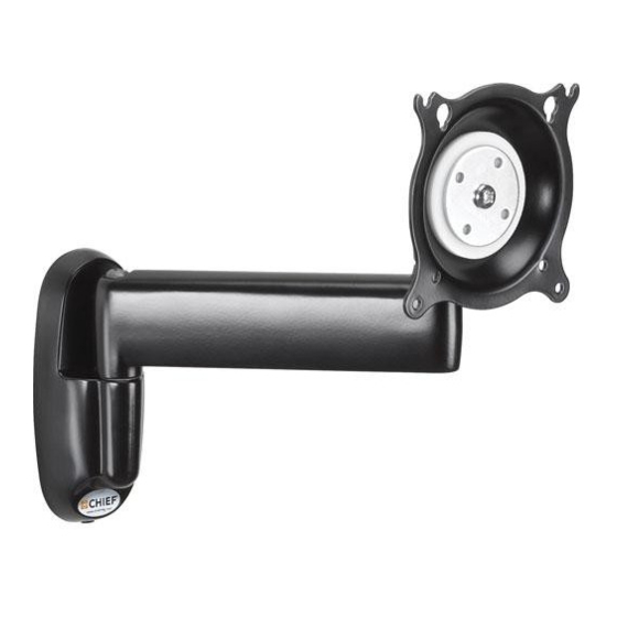
K-Series Mounts (Examples)
8800-002338 Rev.00
©2013 Milestone AV Technologies, a
Duchossois Group Company
www.chiefmfg.com
04/13
Advertisement

Subscribe to Our Youtube Channel
Related Manuals for CHIEF KWP-110


Summary of Contents for CHIEF KWP-110
- Page 1 NOTE: If an accessory such as an optional laptop tray is being installed, complete all required installation procedures within this document prior to installing the accessory. K-Series Mounts (Examples) Chief Manufacturing, a products division of 8800-002338 Rev.00 Milestone AV Technologies ©2013 Milestone AV Technologies, a Duchossois Group Company 6436 City West Parkway, Eden Prairie, MN 55344 www.chiefmfg.com...
- Page 2 WARNING: Do not use this product outdoors. the information contained in this document. --SAVE THESE INSTRUCTIONS-- Chief® is a registered trademark of Milestone AV Technologies. All rights reserved. IMPORTANT SAFETY INSTRUCTIONS WARNING: A WARNING alerts you to the possibility of serious injury or death if you do not follow the instructions.
-
Page 3: Table Of Contents
Model: K-Series Installation Instructions CONTENTS TOOLS REQUIRED FOR INSTALLATION ....................... 3 SPECIFICATIONS ..............................4 MOUNT INSTALLATION ............................5 DISPLAY INSTALLATION ............................8 ARRAY ASSEMBLY (DUAL / TRIPLE DISPLAY; ALL EXCEPT KCY-210/-220)............. 10 MULTI-DUAL ARM ASSEMBLY (KCY-210/-220 ONLY)..................11 CABLE MANAGEMENT ............................12 ADJUSTMENT ................................ -
Page 4: Specifications
NO. OF ADJUSTABLE MAX. MIN. MAX. SUPPORT DISPLAYS STRUCTURE MOUNTING HEIGHT EXTENSION CLOSED WEIGHT ARMS (INCHES) DEPTH (LBS.) (INCHES) PER MONITOR KWP-110 Single Wall None None KWV-110 Single Wall Single KWS-110 Single Wall Single KWG-110 Single Wall Dual 19.5 KWD-110... -
Page 5: Mount Installation
Installation Instructions Model: K-Series MOUNT INSTALLATION IMPORTANT ! : IF you will be installing a SINGLE display with RECESSED mounting holes, then proceed INSTALLATION TO WALL to "DISPLAY INSTALLATION" before continuing with this 1. Verify that you have the following parts: mount installation procedure. - Page 6 Model: K-Series Installation Instructions INSTALLATION TO DESK Two installation options exist: • Edge Installation • Hole (Grommet) Installation; requires 3/8" to 3" diameter hole and access to the bottom of the Clamp Adjustment desk Screw ASSEMBLY 1. Verify that you have the following parts: Edge Item Description...
- Page 7 Installation Instructions Model: K-Series 7. If you are installing: • SINGLE display with RECESSED mounting holes: Proceed to "CABLE MANAGEMENT." Clamp Adjustment • KCY-210/-220: Proceed to "MULTI-DUAL ARM Screw ASSEMBLY." Washer • ALL other display configurations: Proceed to "DISPLAY INSTALLATION." INSTALLATION TO POLE 1.
-
Page 8: Display Installation
Model: K-Series Installation Instructions DISPLAY INSTALLATION 5. Using Phillips screwdriver, install two remaining screws (20) through the lower mounting holes in SINGLE DISPLAY AND KCY-210/-220 Centris bracket into the display. NOTE: If you are installing DUAL / TRIPLE displays 6. Tighten all four screws (20). Do not overtighten! (Except KCY-210/-220), then proceed to page 9. - Page 9 Installation Instructions Model: K-Series 4. Using Phillips screwdriver, install four screws (20) through the mounting holes in Centris bracket into the display (See Figure 13). Tighten all four screws (20). Centris Bracket Do not overtighten! 20 or 30 (4 places) Centris (4 places) Bracket...
-
Page 10: Array Assembly (Dual / Triple Display; All Except Kcy-210/-220)
Model: K-Series Installation Instructions • KSA-1015/-1016 ONLY: Insert large spacer (90), followed by large end of pin (70) and small spacer (80). 20 or 30 Centris (4 places) Bracket 20 or 30 (20 shown; 30 similar) 40 or 50 (4 places) 60 or 70 (60 shown;... -
Page 11: Multi-Dual Arm Assembly (Kcy-210/-220 Only)
Installation Instructions Model: K-Series 8. Using 5/32" hex key, install screw (110) and nut (120) on each end of the array (10) to prevent displays from accidently sliding off (See Figure 17). 80 or Y-connector NOTE: All parts NOTE: Left side shown; right side similar same for both sides. -
Page 12: Cable Management
Model: K-Series Installation Instructions Screw & washers DO NOT POSITION EITHER ARM ASSEMBLY Outer arm IN GRAY SHADED AREA Inner arm spacer or ALLOWABLE AREA Figure 20: Multi-Dual Arm Modification Figure 19: Allowable Arm Area 2. Lift outer arm from pin (with screw and washers) and 7. -
Page 13: Adjustment
Installation Instructions Model: K-Series Attach Screws Cable Path (typical) CLOSED Position OPEN Position View from Bottom Figure 21: Height Adjustable Arm - Cable Management Bracket Figure 23: Static Arm - Cable Path CAUTION: Ensure that adequate cable slack exists for NOTE: Installation is complete. - Page 14 Model: K-Series Installation Instructions HEIGHT ADJUSTABLE (IF APPLICABLE) DUAL / TRIPLE DISPLAY 1. LATERAL POSITION ON ARRAY: • Using your fingers, slightly loosen adjustment IMPORTANT ! : It is important that the mount be knob "A" (See Figure 27). attached to the mounting surface AND display be •...
- Page 15 Installation Instructions Model: K-Series...
- Page 16 Model: K-Series Installation Instructions...
Need help?
Do you have a question about the KWP-110 and is the answer not in the manual?
Questions and answers