Table of Contents
Advertisement
Quick Links
I N S T A L L A T I O N
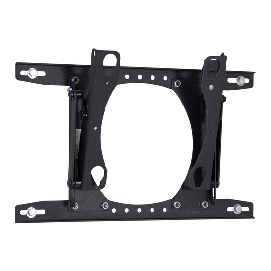
MEDIUM FLAT PANEL DISPLAY TILT MOUNT
The MTR Series tilt mount accommodates medium flat
panel displays weighing up to 100 lbs (45.36kgs).
The teardrop holes in the mount allow for quick
connect/disconnect of the display, thus simplifying
installation and maintenance processes.
The top and bottom mounting brackets are adaptable to
single wood stud mounting or dual wood studs that are
16" on center.
The display can be pulled and tilted into any position in
the zero-to-15 degree tilt range and remain stationary.
When fully retracted, the mount depth is 1.54 inches.
After installing the display on the mount, the screen can
be locked in place using the convenient locking flag.
A padlock can be used on the latching flag for added
security.
The mount is concealed behind the display, making it a
low profile wall mount.
! IMPORTANT: If the installation of this product requires OSHPD seismic approval, refer to OSHPD pre-approval
documents and drawings before beginning installation. OSHPD documents and drawings are available at
www.chiefmfg.com, and located on the product information page for the mount.
BEFORE YOU BEGIN
•
CAUTION: To prevent damage to your monitor and MTR, which could affect or void the Factory
warranty, thoroughly study all instructions and illustrations before you begin to install the mount. Pay
particular attention to the Warnings and Cautions in this document.
•
The mount is designed to be installed using wall studs or supporting framework. The fasteners used to anchor the
mount must be capable of supporting five times the total weight of the equipment.
•
The maximum weight to be installed on the MTR Series tilt wall mount is 100 lbs (45.36kg).
•
If you have any questions about this installation, contact Chief Manufacturing at 1-800-582-6480 or 952-582-6480.
MTR Series
CHIEF MANUFACTURING INC.
1-800-582-6480 952-894-6280 FAX 952-894-6918
8401 EAGLE CREEK PARKWAY, STE. 700
SAVAGE, MINNESOTA 55378 USA
I N S T R U C T I O N S
MTR Series
8805-000137 (Rev. B)
2005 Chief Manufacturing
www.chiefmfg.com
11/05
Advertisement
Table of Contents

Related Manuals for CHIEF MTR Series


Summary of Contents for CHIEF MTR Series
-
Page 1: Before You Begin
• The maximum weight to be installed on the MTR Series tilt wall mount is 100 lbs (45.36kg). • If you have any questions about this installation, contact Chief Manufacturing at 1-800-582-6480 or 952-582-6480. -
Page 2: Dimensional Drawing
Installation Instructions MTR Series IMPORTANT WARNINGS and CAUTIONS! WARNING A WARNING alerts you to the possibility of serious injury or death if you do not follow the instructions. CAUTION A CAUTION alerts you to the possibility of damage or destruction of equipment if you do not follow the corresponding instructions. -
Page 3: Table Of Contents
Installation Instructions MTR Series PARTS LIST CONTENTS Prior to assembly, unpack the carton completely. Verify DIMENSIONAL DRAWING........2 contents listed in Table 1 and Figure 1. TOOLS REQUIRED FOR INSTALLATION....3 Read installation instructions completely. If you are PARTS LIST..............3 missing any of the listed parts, contact Customer Service MTR INSTALLATION ..........4... -
Page 4: Mtr Installation
Installation Instructions MTR Series Wood Stud MTR INSTALLATION Perform the following procedures to mount the MTR. Select Mounting Location Wall Pilot Holes To select the mounting location, do the following: WARNING: It is the responsibility of the installer to verify that the wall to which the mount is... -
Page 5: Mount The Mtr
Installation Instructions MTR Series MTR INSTALLATION (Cont’d) Slotted mounting holes for dual wood studs Mounting holes for Mount the MTR single wood stud To mount the MTR, do the following: NOTE: Lag bolts and washers are not supplied. The lag bolts must be driven into the support wall studs or other supporting framework. -
Page 6: Attach Msb To The Display
Installation Instructions MTR Series ATTACH MSB TO THE DISPLAY Display To attach the MSB to the display, do the following: • To help your identify the correct MSB that matches the model number of your display, refer to the cross- reference chart at www.chiefmfg.com. -
Page 7: Tilt Adjustment
Installation Instructions MTR Series Loosen Nylock nuts on TILT ADJUSTMENT both sides of the mount. Tilt the display into the To set the tilt adjustment of the mount, do the following: desired position. CAUTION: Loosen the nut only. To avoid equipment damage, do not remove the nut from the Re-tighten both nuts.
Need help?
Do you have a question about the MTR Series and is the answer not in the manual?
Questions and answers