Advertisement
Quick Links
I N S T A L L A T I O N I N S T R U C T I O N S
Small Flat Panel Mounts
Model: F-Series
This Instruction Manual covers most of the F-Series wall and desk mounts, as well as selected F-Series pole mounts.
NOTE: Some F-Series mounts (e.g., Table, Pole) and F-
Series accessories have separate Instruction
Manuals.
See Specifications on page 3 for a complete list
of models covered by this Instruction Manual.
IMPORTANT ! : If an accessory such as an optional
laptop tray is being installed, complete all required
installation procedures within this document prior to
installing the accessory.
Chief Manufacturing, a products division of
Milestone AV Technologies
6436 City West Parkway, Eden Prairie, MN 55344
• P: 800.582.6480 / 952.225-6000 • F:877.894.6918 / 952.894.6918
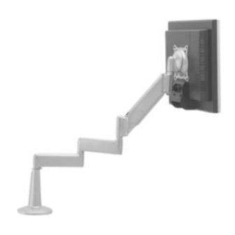
F-Series Mounts (Examples)
8800-002339 Rev00
©2013 Milestone AV Technologies, a
Duchossois Group Company
www.chiefmfg.com
04/13
Advertisement

Subscribe to Our Youtube Channel
Related Manuals for CHIEF FWP-110


Summary of Contents for CHIEF FWP-110
- Page 1 F-Series Mounts (Examples) Chief Manufacturing, a products division of 8800-002339 Rev00 Milestone AV Technologies ©2013 Milestone AV Technologies, a Duchossois Group Company 6436 City West Parkway, Eden Prairie, MN 55344 www.chiefmfg.com...
- Page 2 WARNING: Do not use this product outdoors. the information contained in this document. --SAVE THESE INSTRUCTIONS-- Chief® is a registered trademark of Milestone AV Technologies. All rights reserved. IMPORTANT SAFETY INSTRUCTIONS WARNING: A WARNING alerts you to the possibility of serious injury or death if you do not follow the instructions.
-
Page 3: Table Of Contents
NO. OF ADJUSTABLE MAX. MIN. MAX. DISPLAYS STRUCTURE MOUNTING HEIGHT EXTENSION CLOSED SUPPORT ARMS (INCHES) DEPTH WEIGHT TRAYS (INCHES) (LBS.) FWP-110 Single Wall None None FWV-110 Single Wall Single FWS-110 Single Wall Single FWG-110 Single Wall Dual 19.5 FWD-110 Single... -
Page 4: Mount Installation
Model: F-Series Installation Instructions MOUNT INSTALLATION INSTALLATION TO WALL 1. Verify that you have the following parts: Item Description MOUNT, Wall, F-Series BRACKET, Wall SCREW, Hex Head Lag, 1/4" x 2-1/2" WASHER, Flat Machine Screw, 1/4" 2. Determine location for mount keeping in mind display size, extension, height adjustment (if applicable), and pitch/roll requirements. - Page 5 Installation Instructions Model: F-Series INSTALLATION TO DESK Two installation options exist: • Edge Installation • Hole (Grommet) Installation; requires 3/8" to 3" diameter hole and access to the bottom of the Clamp Adjustment desk Screw ASSEMBLY 1. Verify that you have the following parts: Edge of Desk Item...
- Page 6 Model: F-Series Installation Instructions 5. Center mount (10) over hole. Using 3/16" hex key, securely tighten screw. 6. Drop screw (30) into open (unused) clamp adjustment Clamp Adjustment hole on top of mount (for appearance only). Screw 7. If you are installing: Washer •...
-
Page 7: Display Installation
Installation Instructions Model: F-Series DISPLAY INSTALLATION 5. Using Phillips screwdriver, install two remaining screws (20) through the lower mounting holes in SINGLE DISPLAY AND FCY-210/-220 Centris bracket into the display. NOTE: If you are installing DUAL / TRIPLE displays 6. Tighten all four screws (20). Do not overtighten! FMA-220/-320, then proceed to page 9. - Page 8 Model: F-Series Installation Instructions Centris Bracket 20 or 30 (4 places) 40 or 50 (4 places) Figure 11: Single Display - Recessed Mount CAUTION: Using screws of improper size may damage your display! Proper screws will easily and completely thread into display mounting holes. 8.
- Page 9 Installation Instructions Model: F-Series DUAL / TRIPLE DISPLAY (FMA-220/-320 and Item Description KGL-220 ONLY) SCREW, Phillips Pan Machine, M4 x 20mm 4 per head The mounting holes on the rear of your display will either SCREW, Phillips Pan Machine, M4 x 30mm 4 per head be flush with the rear surface, or recessed into the rear SPACER, Nylon, 3/8"...
-
Page 10: Array Assembly (Dual / Triple Display; Fma-220/-320 Only)
Model: F-Series Installation Instructions ARRAY ASSEMBLY 4. Insert and hold nut (80) into lower mount arm bore (See Figure 14). (DUAL / TRIPLE DISPLAY; FMA-220/-320 ONLY) 5. Insert screw (20 or 30, as applicable) through washer (50), washer (40), washer (50), array (10), array/ 1. -
Page 11: Multi-Dual Arm Assembly (Fcy-210/-220 Only)
Installation Instructions Model: F-Series MULTI-DUAL ARM ASSEMBLY 5. While holding nut (90) in lower bore of Y-connector, insert screw (30) through washer (50), washer (40), (FCY-210/-220, and FGL-220 ONLY) washer (50), arm assembly (10), and Y-connector, into nut (90) (See Figure 17). Loosely install screw BASIC ASSEMBLY (30) using 3/16"... - Page 12 Model: F-Series Installation Instructions MODIFICATION If desired, each arm assembly (10) may be modified to prevent movement of the outer arm relative to the inner arm (without loosening the adjustment screw). NOTE: Spacer (shipped configuration) will allow limited movement of outer arm relative to inner arm, dependent upon tension of screw.
-
Page 13: Cable Management
Installation Instructions Model: F-Series CABLE MANAGEMENT 4. Close cable management bracket by sliding it back towards the centerline of the arm (See Figure 20). NOTE: If necessary, cable management bracket attach screws may be tightened using hex key (30). Item Description COVER, Arm 1 per arm... -
Page 14: Adjustment
Model: F-Series Installation Instructions ADJUSTMENT CENTRIS HEAD SINGLE DISPLAY AND FCY-210/-220 1. If previously attached, disconnect cables from display, PIVOT / SWING then remove display. 2. Using Phillips screwdriver, slightly loosen or tighten the adjustment screw as necessary (See Figure 25). CAUTION: If washer (80) has been used to assemble FCY-210/-220 arms, then forced movement of arms without loosening screw (30) will damage arm and/or Y-... - Page 15 Installation Instructions Model: F-Series...
- Page 16 Model: F-Series Installation Instructions...
Need help?
Do you have a question about the FWP-110 and is the answer not in the manual?
Questions and answers