Table of Contents
Advertisement
Quick Links
I N S T A L L A T I O N
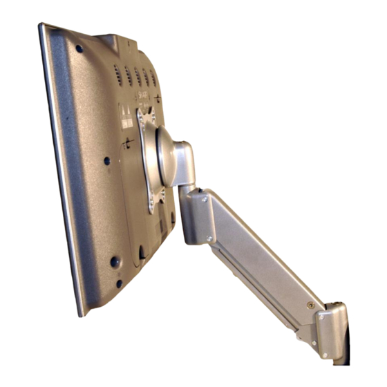
Small Flat Panel
FSA-1004 and KSA-1004
The Lift Arm FSA/KSA-1004 is an accessory that can be
used with a broad range of Small Flat Panel Displays.
The FSA/KSA-1004 allows the user to move a display
vertically up or down in a 13 inch radius. The lift arm can
be moved vertically 6-1/2" up from center and 6-1/2"
down from center.
The FSA/KSA-1004 is designed to safely hold a display
weighing up to 25 lbs. (11.3kg). The display can be up to
30 inches wide.
The FSA/KSA-1004 accommodates all VESA®
75mm/100mm compliant displays.
BEFORE YOU BEGIN
CAUTION: To prevent damage to the mount, which could affect or void the Factory warranty, thoroughly
study all instructions and illustrations before you begin to install the mount brackets. Pay particular atten-
tion to the "Important Precautions" on Page 2.
If you have any questions about this installation, contact Chief Manufacturing at 1-800-582-6480 or 952-582-6480.
Lift Arm
CHIEF MANUFACTURING INC.
1-800-582-6480 952-894-6280 FAX 952-894-6918
8401 EAGLE CREEK PARKWAY, STE. 700
SAVAGE, MINNESOTA 55378 USA
I N S T R U C T I O N S
Lift Arm
8832-000041 Rev. F
©2007 Chief Manufacturing
www.chiefmfg.com
03/07
Advertisement
Table of Contents

Related Manuals for CHIEF FSA-1004


Summary of Contents for CHIEF FSA-1004
-
Page 1: Before You Begin
Pay particular atten- tion to the “Important Precautions” on Page 2. If you have any questions about this installation, contact Chief Manufacturing at 1-800-582-6480 or 952-582-6480. CHIEF MANUFACTURING INC. -
Page 2: Tools Required For Installation
Installation Instructions IMPORTANT WARNINGS and CAUTIONS! WARNING A WARNING alerts you to the possibility of serious injury or death if you do not follow the instructions. CAUTION A CAUTION alerts you to the possibility of damage or destruction of equipment if you do not follow the corresponding instructions. -
Page 3: Parts List
Installation Instructions PARTS PARTS LIST PART Tension adjustment bolt Figure 1. Lift Arm Installation Drawing Table 1. Lift Arm Parts DESCRIPTION LIFT ARM , .640 .845 WASHER UHMW ID X , .318 .031 WASHER UHMWPE ID X PIVOT PIN CAPSCREW BUTTON HEAD LOCK NUT NYLOCK... - Page 4 Installation Instructions INSTALLATION Adding a lift arm modifies your mount configuration. This procedure applies to most small flat panel displays, particularly those with a pivot or swing arm, whether wall mount or desk mount. Removing the Display from the Mount To remove the display from its mount, perform the following steps: NOTE: Do not remove the four screws (not shown) that...
- Page 5 Installation Instructions Installing the Lift Arm To install the lift arm, perform the following procedures: Installing base end of lift arm 1. Locate the tension adjustment bolt on the lift arm (see Figure 3). Install the pivot pin (40) and a washer (20) onto the base of the mount.
- Page 6 Installation Instructions Adjusting Lateral Movement CAUTION: Over-tightening tension bolt will cause excessive wear and may distort adjustment components. To adjust the lateral movement tension, perform the following procedures: 1. Slightly tighten or loosen the tension adjustment bolt. 2. Check for desired tension. Repeat as necessary. Adjusting Lift Arm Tension CAUTION: Over-tightening tension bolt will cause excessive wear and may distort adjustment...
- Page 7 Installation Instructions FSA/KSA-1004...
Need help?
Do you have a question about the FSA-1004 and is the answer not in the manual?
Questions and answers