Table of Contents
Advertisement
I N S T A L L A T I O N I N S T R U C T I O N S
Instrucciones de instalación
Installationsanleitung
Instruções de Instalação
Istruzioni di installazione
Installatie-instructies
Instructions d´installation
Large Swing Arm Mounts
Spanish Product Description
German Product Description
Portuguese Product Description
Italian Product Description
Dutch Product Description
French Product Description
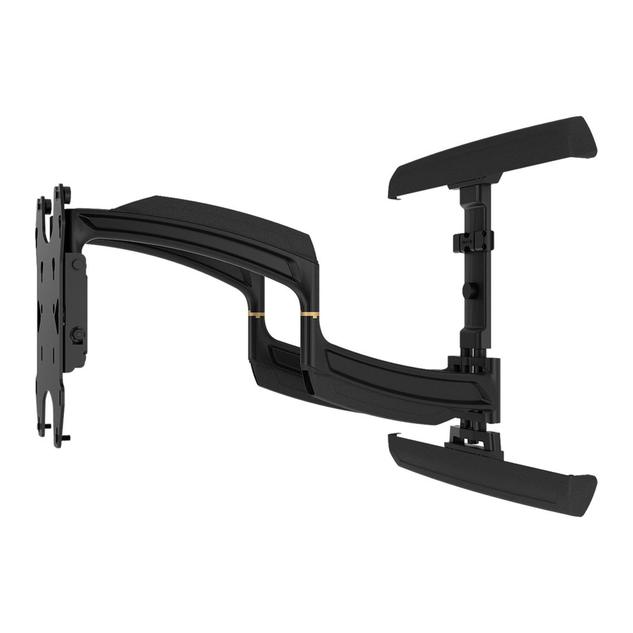
TS525TU
Advertisement
Table of Contents

Subscribe to Our Youtube Channel
Related Manuals for CHIEF TS525TU


Summary of Contents for CHIEF TS525TU
- Page 1 I N S T A L L A T I O N I N S T R U C T I O N S Instrucciones de instalación Istruzioni di installazione Installationsanleitung Installatie-instructies Instruções de Instalação Instructions d´installation Large Swing Arm Mounts Spanish Product Description German Product Description Portuguese Product Description Italian Product Description Dutch Product Description French Product Description TS525TU...
-
Page 2: Installation Instructions
Use with products heavier than the maximum weight the information contained in this document. indicated may result in collapse of the mount and its Chief® is a registered trademark of Milestone AV Technologies. accessories causing possible injury. All rights reserved. - Page 3 Installation Instructions TS525TU DIMENSIONS 39.1 MAXIMUM WEIGHT CAPACITY = 125 lbs. (56.7 kg) DISTANCE FROM WALL 550.28 WITH INTERFACE 21.664 [35.6] 821.19 WITHOUT INTERFACE 32.330 MAX. WIDTH 31.496 MAX. HORIZONTAL PATTERN 406.40 16.000 651.9 17.46 25.67 .688 7.00" [177.8] COLLAPSED...
- Page 4 TS525TU Installation Instructions LEGEND Tighten Fastener Pencil Mark Apretar elemento de fijación Marcar con lápiz Befestigungsteil festziehen Stiftmarkierung Apertar fixador Marcar com lápis Serrare il fissaggio Segno a matita Bevestiging vastdraaien Potloodmerkteken Serrez les fixations Marquage au crayon Loosen Fastener Drill Hole Aflojar elemento de fijación...
-
Page 5: Tools Required For Installation
Installation Instructions TS525TU TOOLS REQUIRED FOR INSTALLATION concrete only 13/64" (5.1mm) - wood studs 1/2" (12.7mm) 3/8" (10mm) - concrete PARTS A2 (6) A1 (6) A3 (6) "A" N (1) M4x25mm M4x16mm [wall rail] M4x10mm M (1) [main assembly] B1 (6) B3 (6) "B"... -
Page 6: Assembly And Installation
TS525TU Installation Instructions Assembly And Installation Install Wall Plate to Wall - Wood Studs WARNING: Failure to provide adequate structural strength for this component can result in serious personal injury or (F) x 2 damage to equipment! It is the installer’s responsibility to make sure the structure to which this component is attached can support five times the combined weight of all equipment. - Page 7 DO NOT REMOVE SPACER AS SHOWN concrete at least 8" in depth or into 8"x8"x16" concrete BELOW PRIOR TO INSTALLING THE LOWER TWO LAG blocks! Never install the TS525TU into cracked, chipped or SCREWS OR THE MOUNT WILL FALL OFF THE WALL flaking concrete.
- Page 8 TS525TU Installation Instructions Install two concrete anchors (G) into two drilled holes. (See Figure 7) center of wall rail Loosely attach wall rail (N) to wall by installing two 5/16- 2 1/2 flange head lag screws (F) into concrete anchors (G).
- Page 9 Installation Instructions TS525TU 15. Loosely install two 5/16 x 2 1/2" flange head lag screws (F) through lower wall rail on main assembly and into concrete anchors. (See Figure 10) 16. Place two installation spacers (H) over two flange head lag screws (F).
- Page 10 TS525TU Installation Instructions Install Interface Bracket to Display IMPORTANT ! : If the displays hole pattern size is (D) x4 100mm x100mm, 200mm x 200mm or 100mm x 200mm, (A-C) x4,x6,x8 or the display can be mounted directly to the faceplate and the interface bracket DOES NOT need to be installed! Proceed to Install Display section.
- Page 11 TS525TU Installation Instructions Connect top interface support (R) to uprights (P and Q) using four #10-24 x 1/2" button head cap screws (W). (See Figure 14) (W) x 4 NOTE: If possible install screws diagonally across from each other in order to provide maximum support in Steps 8 and 9.
- Page 12 TS525TU Installation Instructions Installing Display Without Interface Bracket (100x100, 200x200 or 100x200) (200 x 200 shown) CAUTION: Using screws of improper diameter may damage your display! Proper screws will easily thread into (K) x 2 with (A) display mounting holes.
-
Page 13: Cable Management
Installation Instructions TS525TU Cable Management Make all cable connections to display. Open cable management covers on upper and lower swing remove and replace arms. (See Figure 19) with (V) Route cables on top of upper arm. (See Figure 19) (Optional) Use cable ties (not included) to secure cables to upper arms by threading ties around cable and through cable tie holes on arms. -
Page 14: Lateral Shift Adjustment
TS525TU Installation Instructions Leveling Friction Adjustment Lateral Shift Adjustment Adjust leveling adjustment screw on back of faceplate to Remove wall rail covers (N) to expose lateral shift increase or decrease leveling friction. (See Figure 22) adjustment screws on wall rails. - Page 15 Installation Instructions TS525TU Arm Tension Adjustment Install Interface Bracket Adhesive Covers (Optional) Use 1/4" hex key (AA) to adjust arm tension at any of the four arm tension adjustment points. (See Figure 25) If the interface bracket was required to install display to mount, adhesive covers may be used to cover the holes on the interface bracket in order to improve the appearance.
- Page 16 Europe A Franklinstraat 14, 6003 DK Weert, Netherlands P +31 (0) 495 580 852 F +31 (0) 495 580 845 Chief Manufacturing, a products division Asia Pacific A Office No. 1 on 12/F, Shatin Galleria of Milestone AV Technologies 18-24 Shan Mei Street...
Need help?
Do you have a question about the TS525TU and is the answer not in the manual?
Questions and answers