Table of Contents
Advertisement
Quick Links
I N S T A L L A T I O N I N S T R U C T I O N S
Instrucciones de instalación
Installationsanleitung
Instruções de Instalação
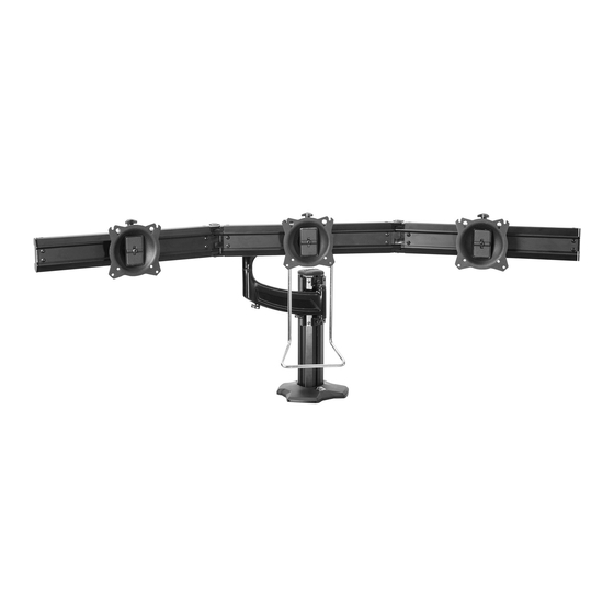
Kontour™ Articulating Array Arm Grommet Series
Istruzioni di installazione
Installatie-instructies
Instructions d´installation
K4G210
K4G310
Spanish Product Description
German Product Description
Portuguese Product Description
K4G210-310
Italian Product Description
Dutch Product Description
French Product Description
Advertisement
Table of Contents

Related Manuals for CHIEF Kontour K4G310


Summary of Contents for CHIEF Kontour K4G310
- Page 1 I N S T A L L A T I O N I N S T R U C T I O N S Instrucciones de instalación Istruzioni di installazione Installationsanleitung Installatie-instructies Instruções de Instalação Instructions d´installation K4G210 K4G310 Kontour™ Articulating Array Arm Grommet Series Spanish Product Description German Product Description Portuguese Product Description...
-
Page 2: Important Safety Instructions
Milestone assumes no responsibility for accuracy, completeness or sufficiency of the information contained in this document. Chief® is a registered trademark of Milestone AV Technologies. All rights reserved. IMPORTANT SAFETY INSTRUCTIONS WARNING: A WARNING alerts you to the possibility of serious injury or death if you do not follow the instructions. - Page 3 Installation Instructions K4G210-310 DIMENSIONS K4G210 20° MAX ANGLE 16.20 37.13 7.13 411.5 943.2 181.1 EXTENSION MAX DISTANCE VESA 100 X 100 75 X 75 COMPATIBLE INTERFACES 15.28 TILT ADJUSTMENT TILT ADJUSTMENT 388.2 ±12° ±12° + 3.00 [76.2] - 3.75 [95.3] 2.27 57.6 4.94...
- Page 4 K4G210-310 Installation Instructions LEGEND Tighten Fastener Pencil Mark Apretar elemento de fijación Marcar con lápiz Befestigungsteil festziehen Stiftmarkierung Apertar fixador Marcar com lápis Serrare il fissaggio Segno a matita Bevestiging vastdraaien Potloodmerkteken Serrez les fixations Marquage au crayon Loosen Fastener Drill Hole Aflojar elemento de fijación Perforar...
-
Page 5: Tools Required For Installation
Installation Instructions K4G210-310 TOOLS REQUIRED FOR INSTALLATION 1/2” 5/16” (included) 3/16” (included) 5/32” (included) 1/8” (included) PARTS Hardware bag (parts numbered on bag as shown) G (2) A2 (2) A1 (2) B1 (2) B2 (2) [handle clamp] 3/8-16 x 2 3/4” 3/8”... -
Page 6: Assembly And Installation
K4G210-310 Installation Instructions Assembly And Installation Insert grommet screw (T) through grommet hole and thread into center hole of grommet plate (U). (See Figure 3) Use four 1/4-20 x 1 1/4” flat head cap screws (C) to secure Tighten grommet screw (T) until grommet base is tightened grommet plate (U) to column (CC). - Page 7 Installation Instructions K4G210-310 10. Loosely install two 1/4-20 x 1/2” socket head carriage screws (B1) through mounting holes on column arm (Z) (K4G210 shown) bracket and into 1/4” square nuts (B2). (See Figure 5) (A1) x 2 11. Slide column arm (Z) bracket into column (CC) until desired mounting height is reached.
-
Page 8: Display Installation
K4G210-310 Installation Instructions 20. Use two #10-32 x 3/8” Phillips pan machine screws (D1) and two handle clamps (G) to secure handle (H) to array (K4G210 shown) center (AA or BB). (See Figure 12) (AA) (K4G310 shown) (G) x 2 (D2) x 2 Figure 9 17. - Page 9 Installation Instructions K4G210-310 Flush Mounting Holes Tighten all four screws (P). Do not over-tighten! Position faceplate in desired mounting position. Adjust as NOTE: If roll adjustment is desired for center faceplate, do not required before proceeding. See Height Adjustment Section tighten screws.
- Page 10 K4G210-310 Installation Instructions Slide two remaining selected spacers (Q or R) in between Pivot Adjustment (Column Arm) faceplate and display, positioning them over the lower two mounting holes. (See Figure 16) Use handle to extend or collapse column arm (Z) as desired.
- Page 11 Installation Instructions K4G210-310 Faceplate Assembly Removal Lateral Shift Remove hex head bolt from bottom of faceplate assembly. Loosen knob on top of faceplate assembly until faceplate (See Figure 20) can slide freely along array. (See Figure 22) Slide out removable plate from bottom of faceplate Adjust lateral position as desired.
-
Page 12: Cable Management
K4G210-310 Installation Instructions Cable Management Route cables along mounting arms. (See Figure 26) Route cables from display through cable management Use cable ties (not included) to secure cables to tie clips covers (V) as desired. (See Figure 24) (E1). (See Figure 26) Install cable management covers (V) onto array arms (X NOTE: Leave enough slack in the cables so that arm may still... - Page 13 Installation Instructions K4G210-310...
- Page 14 K4G210-310 Installation Instructions...
- Page 15 Installation Instructions K4G210-310...
- Page 16 Europe A Franklinstraat 14, 6003 DK Weert, Netherlands P +31 (0) 495 580 852 F +31 (0) 495 580 845 Chief, a products division of Asia Pacific A Office No. 1 on 12/F, Shatin Galleria Milestone AV Technologies 18-24 Shan Mei Street...
Need help?
Do you have a question about the Kontour K4G310 and is the answer not in the manual?
Questions and answers