Table of Contents
Advertisement
Quick Links
I N S T A L L A T I O N I N S T R U C T I O N S
Instrucciones de instalación
Installationsanleitung
Instruções de Instalação
WM-210SI
WM-230SI
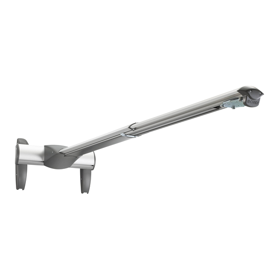
Dual Stud Short Throw Wall Mounts
WM210-220-230-240S/SI
Istruzioni di installazione
Installatie-instructies
Instructions d´installation
WM-220SI
WM-240SI
Spanish Product Description
German Product Description
Portuguese Product Description
Italian Product Description
Dutch Product Description
French Product Description
Advertisement
Table of Contents

Related Manuals for CHIEF WM210S


Summary of Contents for CHIEF WM210S
- Page 1 I N S T A L L A T I O N I N S T R U C T I O N S Instrucciones de instalación Istruzioni di installazione Installationsanleitung Installatie-instructies Instruções de Instalação Instructions d´installation WM-210SI WM-220SI WM-240SI WM-230SI Dual Stud Short Throw Wall Mounts Spanish Product Description...
-
Page 2: Table Of Contents
(and including) the projector does not exceed 50 lbs WARNING: A WARNING alerts you to the possibility of (22.68 kg) for the WM210S/SI or WM220S/SI; or 25 lbs serious injury or death if you do not follow the instructions. (11.34 kg) for the WM230S/SI or WM240S/SI. -
Page 3: Dimensions
Installation Instructions WM210-220-230-240S/SI DIMENSIONS WM2XXS (Standard Model) 240S, TRAVEL 37.2" - 65.6" 16.00 210S, TRAVEL 12.75" - 19.5" 3.96 7.25 7.25 10.81 11.53 3 OF 5.64 5.36 19.63 1.42 1.09 CABLE CHANNEL DIMENSIONS: INCHES DIMENSIONS THRU ARM WM2XXSI (Interactive Model) 240SI, TRAVEL 37.2"... -
Page 4: Legend
WM210-220-230-240S/SI Installation Instructions LEGEND Pencil Mark Tighten Fastener Marcar con lápiz Apretar elemento de fijación Stiftmarkierung Befestigungsteil festziehen Marcar com lápis Apertar fixador Segno a matita Serrare il fissaggio Potloodmerkteken Bevestiging vastdraaien Marquage au crayon Serrez les fixations Drill Hole Loosen Fastener Perforar Aflojar elemento de fijación... -
Page 5: Parts
Installation Instructions WM210-220-230-240S/SI TOOLS REQUIRED FOR INSTALLATION 5/32" 3/16" (included) (included) (security) 5/32" - 6" long (included) 1/2" (12.7mm) 1/2" (12.7mm) (security) 3/8" (9.5mm) 7/32" (5.6mm) PARTS (WM2XXS All Models Models Only) A (1) [Short throw wall mount] AJ (1) [Upper cover] WM-210 WM-220... -
Page 6: Site Requirements
WM210-220-230-240S/SI Installation Instructions SITE REQUIREMENTS (WM2XXS and WM2XXS Models) - Steel Stud Structure WARNING: IMPROPER INSTALLATION CAN LEAD TO EQUIPMENT FALLING CAUSING SERIOUS PERSONAL INJURY OR DAMAGE TO EQUIPMENT! The figure below identifies the minimum requirements for installation of display mounts onto a steel stud structure. -
Page 7: Ws2Xxsi Interactive Mount Only
WS2XXS INTERACTIVE MODEL ONLY • The interactive mount includes a USB cable. The Chief Interactive Mount (WM2XXSI) works with standard projectors and Windows® and Macintosh® computers. The Interactive Mount will transform existing whiteboards or other Screen Recording Requirements hard, flat surfaces, into interactive whiteboards and allows users to present, annotate, and interact with their projected (Currently available only on Windows platform.) - Page 8 The projection image should start a minimum of 1 inch from the base of the top frame of the whiteboard. • The projection image should be positioned within the fan area extending from the Chief Interactive Dual Mount. This fan area should not exceed 140 degrees. Whiteboard Constraints •...
-
Page 9: Assembly And Installation
Installation Instructions WM210-220-230-240S/SI ASSEMBLY AND INSTALLATION - (WM2XXSI and WM2XXS MODELS) (L) x 4 The WM-210S/SI, -220S/SI, -230S/SI and -240S/SI short throw (M) x 4 projector mounts can be mounted to concrete, concrete block, (K) x 4 wood studs or steel studs. They can be mounted to 2" x 4" wood studs up to 16"... - Page 10 WM210-220-230-240S/SI Installation Instructions Install four 5/16 x 2-1/2" hex head lag screws (L) through Hold metal channel on anchor (P) flat alongside plastic four 5/16" washers (M), holes of wall bracket and into drilled straps and slide channel through hole. (See Figure 9) holes.
-
Page 11: Installation To Wall Bracket
Installation Instructions WM210-220-230-240S/SI 10. Place wall bracket over anchors and align mounting holes Slide lower plate onto cross bracket on mounting bracket. in display mount with holes in anchors. (See Figure 12) (See Figure 14) 11. Insert 1/4-20 x 1-3/4" Phillips pan head screws (N) through 1/4"... -
Page 12: Projector Installation
RSM holes and into projector mounting plate. (See up to (and including) the projector does not exceed 50 lbs Figure 19) (22.68 kg) for the WM210S/SI or the WM220S/SI or 25 lbs (11.34 kg) for the WM230S/SI or WM240S/SI. NOTE: RPM, RPA and RSA are sold separately. -
Page 13: Wm2Xxsi Interactive Mount
Installation Instructions WM210-220-230-240S/SI RPA Installation Line up mounting holes on RPA mount with corresponding IMPORTANT ! : Complete the installation by holes on projector mounting plate. (See Figure 17) proceeding to WM2XXSI Interactive Mount section or Install four 1/4-20 x 3/8" Phillips pan machine screws (G) WM2XXS Standard Mount section, as appropriate. -
Page 14: Cable Management (Optional)
WM210-220-230-240S/SI Installation Instructions Lower the upper cover (X) onto the wall mount and lower Remove and save two 8-32 x 3/8" Phillips pan head screws cover, and fasten with two 8-32 x 3/8" Phillips pan head (AB) from lower cover. (See Figure 26) screws (AB). - Page 15 Installation Instructions WM210-220-230-240S/SI NOTE: Cables may be routed from below and up wall bracket channel, or from above and down behind and into wall (view from front) mount. Cables • Routing Cables from Below (Steps 6 and 7) Open cable clips along bottom edge of wall bracket. (See Surface Mount Figure 28) Cable Accessory...
-
Page 16: Installation Of Wall Bracket Covers
WM210-220-230-240S/SI Installation Instructions Installation of Wall Bracket Covers 10. (Optional) Cables can be tied to inside of mount’s front cover using cable ties (not included). Route cables near front cover and wrap cable tie through slots on front cover NOTE: If security screws are going to be used, use the security and around cables. -
Page 17: Adjustments
Installation Instructions WM210-220-230-240S/SI Adjustments Loosen two bolts on either side of pitch adjustment screw. (See Figure 38) Bracket Width Adjustment Adjust pitch adjustment screw until mount is at desired pitch level. Turn clockwise to raise mounting level or turn Loosen two flat head cap screws on wall bracket. (See counterclockwise to lower mounting level. -
Page 18: Security Screw Installation (Optional)
WM210-220-230-240S/SI Installation Instructions Lateral Shift Adjustment Install eight #8-32 x 1/2" button head security screws (V) into holes in wall bracket covers. (See Figure 42) IMPORTANT ! : The mount covers need to be removed before proceeding with lateral shift adjustment. NOTE: Remove mount covers from the mount following (V) x 8... - Page 19 Installation Instructions WM210-220-230-240S/SI Remove two 8-32 x 3/8" Phillips pan head screws (AB) from lower cover. (See Figure 44) (AA) x 2 (AB) x 2 Figure 46 Lower cover Stop Bracket Remove two bolts holding stop bracket in place on underside of short throw projector mount.
- Page 20 WM210-220-230-240S/SI Installation Instructions Install two 1/4-20 x 1/2" button head security screws (T) through holes in stop bracket and into holes in sliding nuts. (See Figure 48) Adapter plate Sliding nuts locations Stop bracket (T) x 2 x 4 (one at a time) Figure 48 Figure 49 Adapter Plate Bolts...
-
Page 21: Wm2Xxs Standard Mount
Installation Instructions WM210-220-230-240S/SI WM2XXS STANDARD MOUNT Cable Management (Optional) Installing Mount Covers In most cases, cable management covers will NOT need to be removed in order to route cables from projector to the wall Raise the lower cover (AK) to wall mount and hold in place. mount. - Page 22 WM210-220-230-240S/SI Installation Instructions Remove cable management covers (if necessary) from short throw projector arm. (See Figure 55) (bottom view) Cables (example) Cable management Figure 57 covers • Routing Cables from Above (Step 7) Thread cables down through a surface mount cable accessory (not included), then behind and into the wall Figure 55 bracket.
-
Page 23: Installation Of Wall Bracket Covers
Installation Instructions WM210-220-230-240S/SI Route cables through cover mount, projector arm tunnel and into projector. (See Figure 59) Cables (example) Figure 61 Cable clips 11. Return outer covers to the mount following instructions in Installing Mount Covers section. Installation of Wall Bracket Covers NOTE: If security screws are going to be used, use the security screws (V) to install wall bracket covers. -
Page 24: Adjustments
WM210-220-230-240S/SI Installation Instructions Secure wall bracket bottom caps (D) to wall bracket arms by Loosen two 1/4-20 x 5/8" hex head cap screws (E) on installing four #8-32 x 1/2" Phillips pan machine screws (F) underside of mounting bracket. (See Figure 65) through holes in covers and wall bracket. -
Page 25: Security Screw Installation (Optional)
Installation Instructions WM210-220-230-240S/SI Security Screw Installation (Optional) (bottom view) Wall Bracket Covers Remove eight #8-32 x 1/2" Phillips pan machine screws (F) from wall bracket covers. (See Figure 69) (F) x 8 Figure 67 Lateral Shift Adjustment IMPORTANT ! : The mount covers need to be removed (Projector arm not shown before proceeding with lateral shift adjustment. - Page 26 WM210-220-230-240S/SI Installation Instructions Mount Covers Remove two #8-32 x 1/2" Phillips pan machine screws (F) Stop bracket holding mount covers on projector arm. (See Figure 71) Install two #8-32 x 1/2" button head security screws (V) into holes on mount cover. (See Figure 71) (F) x 2 Figure 72 Install two 1/4-20 x 1/2"...
- Page 27 Installation Instructions WM210-220-230-240S/SI Adapter Plate Bolts Remove projector from short throw projector mount according to projector interface instructions. Adapter plate NOTE: For most projectors, it will be necessary to remove projector prior to installing four security screws to Plastic spacer projector bracket.
- Page 28 Europe A Franklinstraat 14, 6003 DK Weert, Netherlands P +31 (0) 495 580 852 F +31 (0) 495 580 845 Chief Manufacturing, a products division Asia Pacific A Office No. 1 on 12/F, Shatin Galleria of Milestone AV Technologies 18-24 Shan Mei Street...
Need help?
Do you have a question about the WM210S and is the answer not in the manual?
Questions and answers