Table of Contents
Advertisement
Quick Links
I N S T A L L A T I O N I N S T R U C T I O N S
Instrucciones de instalación
Installationsanleitung
Instruções de Instalação
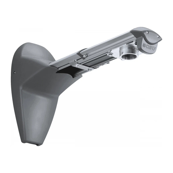
Single Stud Wall Mount Accessory
Istruzioni di installazione
Installatie-instructies
Instructions d´installation
Spanish Product Description
German Product Description
Portuguese Product Description
Italian Product Description
Dutch Product Description
French Product Description
WMA1S
Advertisement
Table of Contents

Related Manuals for CHIEF WMA1S


Summary of Contents for CHIEF WMA1S
- Page 1 I N S T A L L A T I O N I N S T R U C T I O N S Instrucciones de instalación Istruzioni di installazione Installationsanleitung Installatie-instructies Instruções de Instalação Instructions d´installation Single Stud Wall Mount Accessory Spanish Product Description German Product Description Portuguese Product Description Italian Product Description Dutch Product Description French Product Description WMA1S...
-
Page 2: Installation Instructions
Chief® is a registered trademark of Milestone AV Technologies. Reinforce the structure as required before installing the All rights reserved. - Page 3 Installation Instructions WMA1S LEGEND Tighten Fastener Pencil Mark Apretar elemento de fijación Marcar con lápiz Befestigungsteil festziehen Stiftmarkierung Apertar fixador Marcar com lápis Serrare il fissaggio Segno a matita Bevestiging vastdraaien Potloodmerkteken Serrez les fixations Marquage au crayon Loosen Fastener Drill Hole Aflojar elemento de fijación...
-
Page 4: Tools Required For Installation
(included) (security) 1/2" (12.7mm) steel stud 3/8" (10mm) concrete and concrete block 7/32" (5.6mm) wood 2" x 4" stud PARTS A (1) [WMA1S Assembly] B (1) [Wall bracket] F (4) 1/4-20 x 1-3/4" C (4) G (4) 5/16 x 2-1/2"... -
Page 5: Site Requirements
Installation Instructions WMA1S Site Requirements WARNING: IMPROPER INSTALLATION CAN LEAD TO EQUIPMENT FALLING CAUSING SERIOUS PERSONAL INJURY OR DAMAGE TO EQUIPMENT! The figure below identifies the minimum requirements for installation of display mounts onto a steel stud structure. If the structure or its components do not meet these requirements contact the mount manufacturer for specific instructions before attempting installation. -
Page 6: Assembly And Installation
WMA1S Installation Instructions ASSEMBLY AND INSTALLATION The WMA1S single stud wall mount accessory can be mounted to concrete, concrete block, 2" x 4" wood studs or steel studs. Installing Mounting Bracket WARNING: ELECTRICAL SHOCK HAZARD! CUTTING OR DRILLING INTO ELECTRICAL CORDS OR CABLES... - Page 7 Installation Instructions WMA1S Install three 5/16 x 2-1/2" hex head lag screws (C) through Hold metal channel on anchor (G) flat alongside plastic three 5/16" washers (D), inner holes of wall bracket (B) and straps and slide channel through hole. (See Figure 6) into drilled holes.
-
Page 8: Installation To Wall Bracket
Snap off plastic straps on anchor at wall by pushing side to Installation to Wall Bracket side, snapping off straps level with flange of plastic cap. Lift WMA1S assembly (A) up to wall bracket (B) and hook (See Figure 8) upper plate over upper notches on bracket. (See Figure 10) Repeat Steps 5 through 8 for each mounting hole. -
Page 9: Installing Mount Covers
Installation Instructions WMA1S Installing Mount Covers PROJECTOR INSTALLATION Raise lower cover (X) up to WMA1S. (See Figure 12) WARNING: Exceeding the weight capacity can result in serious personal injury or damage to equipment! It is the installer’s responsibility to make sure the combined weight... -
Page 10: Removing Mount Covers
Remove two #8 x 1/2" Phillips pan tapping screws (U) and two #10 x 1" Phillips pan tapping screws (V) to free top cover (W) and expose pitch adjustment screw. (See Figure 15) Pitch adjustment Remove lower cover (X) from WMA1S. (See Figure 15) screw Lower Raise (V) x 2... - Page 11 WMA1S arm. (See Figure 18) Figure 18 Figure 20 (Optional) Cables may be tied to inside of WMA1S front cover using cable ties (not included). Route cables near Extension Adjustment front cover and wrap cable tie through slots on front cover and around cables.
-
Page 12: Security Screw Installation (Optional)
Remove two bolts holding stop bracket in place on underside of WMA1S. (See Figure 23) most mounts, it will be necessary to remove column prior to install of four security screws to WMA1S. Remove one of four bolts from adapter plate. (See Figure 25) Stop bracket... - Page 13 Installation Instructions WMA1S Install one 1/4-20 x 3/4" button head security screw (K) into hole vacated by removing bolt in Step 6 and into plastic spacer. (See Figure 26) Repeat Steps 6-7 for remaining three bolts one bolt at a time.
- Page 14 WMA1S Installation Instructions...
- Page 15 Installation Instructions WMA1S...
- Page 16 Europe A Fellenoord 130 5611 ZB EINDHOVEN, The Netherlands P +31 (0)40 2668620 F +31 (0)40 2668615 Chief Manufacturing, a products division Asia Pacific A Office No. 1 on 12/F, Shatin Galleria of Milestone AV Technologies 18-24 Shan Mei Street...
Need help?
Do you have a question about the WMA1S and is the answer not in the manual?
Questions and answers