
Subscribe to Our Youtube Channel
Related Manuals for Billion BiPAC 8200N


Summary of Contents for Billion BiPAC 8200N
-
Page 1: User Manual
BiPAC 8200N 802.11n VDSL2 Firewall Router User Manual Firmware Version 1.02f Last revised on Mar 2010... -
Page 2: Table Of Contents
Table of Contents Chapter 1: Product ................1 Introduction to your Router ............1 Features ..................4 Hardware Specifications ............5 Chapter 2: Product Overview............6 Package Contents ............... 6 Important note for using this router ..........6 Device Description ..............7 The Front LEDs ...................7 The Rear Ports ...................8 Cabling .................. - Page 3 Obtain IP Address Automatically (VDSL) ............35 Fixed IP Address (VDSL) ................36 PPPoE Connection (VDSL) ................37 Pure Bridge (VDSL) ..................38 WAN – Main Port: EWAN ..............39 Obtain IP Address Automatically (EWAN) ............39 Fixed IP Address (EWAN) ................40 PPPoE Connection (EWAN) ................
-
Page 4: Chapter 1: Product
Chapter 1: Product Introduction to your Router Thank you for purchasing BiPAC 8200N Router. Your new router is an all-in-one unit that combines a VDSL modem, VDSL2 router and Ethernet network switch to provide everything you need to get the machines on your network connected to the Internet over a VDSL broadband connection. - Page 5 EWAN Besides using VDSL to get connected to the Internet, this router offers its Ethernet port 4 as a WAN port to be used to connect to Cable Modems and fiber optic lines. This alternative, yet faster method to connect to the internet will provide users more flexibility to get online. Multi-Protocol to Establish a Connection The router supports PPP over Ethernet, DHCP Client and Fixed IP address to establish a connection with an ISP.
- Page 6 Quality of Service (QoS) QoS gives you full control over which types of outgoing data traffic should be given priority by the router, ensuring important data like gaming packets, customer information, or management information move through the router ay lightning speed, even under heavy load. The QoS features are configurable by Internal IP address, External IP address, protocol, and port.
-
Page 7: Features
Features • Compliant with ITU-T G.993.2 , G.994.1 and G.997.1 VDSL2 Standard • VDSL2 Profiles: 8a/b/c/d, 12a/b, 17a, 30a • Band Plan 997 and 998 supported • Annex A, Annex B, Annex C supported • US0 Supported • OLR Supported •... -
Page 8: Hardware Specifications
Hardware Specifications Physical Interface • WLAN: 2 x antennae • DSL: VDSL port • Ethernet: 4-port 10/100Mbps auto-crossover (MDI / MDI-X) Switch • Reset button • WPS push button • Power jack • Power switch... -
Page 9: Chapter 2: Product Overview
Chapter 2: Product Overview Package Contents • 8200N 802.11n VDSL2 Firewall Router • Antenna x 2 • CD containing the on-line manual • RJ-11 xDSL / telephone cable • Ethernet (RJ-45) cable • Power adapter • Quick Start Guide • Splitter / Micro-filter (Optional) Important note for using this router... -
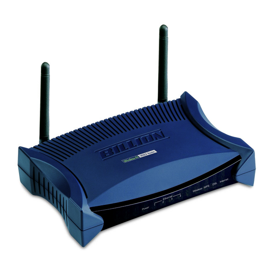
Page 10: Device Description
Device Description The Front LEDs Meaning Lit red when the device is booting. Power Lit green when the system is ready. Flashes when the system is rebooting or firmware upgrading. Lit when one of LAN ports is connected to an Ethernet device. Ethernet port Lit green when the speed of transmission hits 100Mbps;... -
Page 11: The Rear Ports
The Rear Ports Port Meaning Connect this port to the VDSL/telephone network with the RJ-11 cable (telephone) provided. Connect a UTP Ethernet cable (Cat-5 or Cat-5e) to one of the four LAN ports when connecting to a PC or an office/home network of 10Mbps or Ethernet 100Mbps. - Page 12 Recovery Operation 1. Recovery procedures for non-working routers (e.g. after a failed firmware upgrade flash): The system will check the firmware of this device automatically while turning on the modem. Once the firmware is not integrated, the system enters the recovery state. The modem emergency- reflash web interface will then be accessible via http://192.168.1.254 where you can upload a firmware image to restore the modem to a functional state.
-
Page 13: Cabling
Cabling One of the most common causes of problems is because of bad cabling or VDSL line(s). Make sure that all connected devices are turned on. On the front of the product is a bank of LEDs. Verify that the LAN Link and VDSL line LEDs are lit. If they are not, verify that you are using the proper cables. -
Page 14: Chapter 3: Basic Installation
Chapter 3: Basic Installation The router can be configured through your web browser. A web browser is included as a standard application in the following operating systems: Linux, Mac OS, Windows 98/NT/2000/XP/Me/ Vista/7, etc. The product provides an easy and user-friendly interface for configuration. Please check your PC network components. -
Page 15: Applications Of The Device
Applications of the device Deployment scenario for VDSL using FTTx... -
Page 16: Network Configuration
Network Configuration Configuring PC in Windows 7 1. Go to Start. Click on Control Panel. 2. Then click on Network and Internet. 3. When the Network and Sharing Center window pops up, select and click on Change adapter settings on the left window panel. 4. - Page 17 5. Select Internet Protocol Version 4 (TCP/IPv4) then click Properties. 6. In the TCP/IPv4 properties window, select the Obtain an IP address au- tomatically and Obtain DNS Server address automatically radio but- tons. Then click OK to exit the set- ting.
-
Page 18: Configuring Pc In Windows Vista
Configuring PC in Windows Vista 1. Go to Start. Click on Network. 2. Then click on Network and Sharing Center at the top bar. 3. When the Network and Sharing Center window pops up, select and click on Manage network connec- tions on the left window column. - Page 19 5. Select Internet Protocol Version 4 (TCP/IPv4) then click Properties. 6. In the TCP/IPv4 properties window, select the Obtain an IP address au- tomatically and Obtain DNS Server address automatically radio but- tons. Then click OK to exit the set- ting.
-
Page 20: Configuring Pc In Windows Xp
Configuring PC in Windows XP 1. Go to Start > Control Panel (in Classic View). In the Control Panel, double-click on Network Connections 2. Double-click Local Area Connection. 3. In the Local Area Connection Status window, click Properties. 4. Select Internet Protocol (TCP/IP) and click Properties. -
Page 21: Configuring Pc In Windows 2000
Configuring PC in Windows 2000 1. Go to Start > Settings > Control Panel. In the Control Panel, double-click on Network and Dial-up Connections. 2. Double-click Local Area Connection. 3. In the Local Area Connection Status window click Properties. 4. Select Internet Protocol (TCP/IP) and click Properties. -
Page 22: Configuring Pc In Windows 95/98/Me
Configuring PC in Windows 95/98/Me 1. Go to Start > Settings > Control Panel. In the Control Panel, double-click on Network and choose the Configuration tab. 2. Select TCP/IP > NE2000 Compatible, or the name of your Network Interface Card (NIC) in your PC. 3. -
Page 23: Configuring Pc In Windows Nt4.0
Configuring PC in Windows NT4.0 1. Go to Start > Settings > Control Panel. In the Control Panel, double-click on Network and choose the Protocols tab. 2. Select TCP/IP Protocol and click Prop- erties. 3. Select the Obtain an IP address from a DHCP server radio button and click... -
Page 24: Factory Default Settings
Factory Default Settings Before configuring your router, you need to know the following default settings. Web Interface (Username and Password) Username: admin Password: admin The default username and password are “admin” and “admin” respectively. Device LAN IP settings IP Address: 192.168.1.254 Subnet Mask: 255.255.255.0 ISP setting in WAN site PPPoE... -
Page 25: Information From Your Isp
Information from your ISP Before configuring this device, you have to check with your ISP (Internet Service Provider) to find out what kind of service is provided such as PPPoE, Obtain an IP Address Automatically (DHCP), Fixed IP Address (Static IP). Gather the information as illustrated in the following table and keep it for reference. -
Page 26: Chapter 4: Configuration
GUI for any detail configuration. This configuration method is usually auto initiated if user is to connect to the internet via Billion's router for the first time. After setting up the router with all the appropriate cables plugged-in, open up your IE browser, the EZSO WEB GUI will automatically pop up and request that you enter some basic information that you have obtained from your ISP. - Page 27 4. Please enter all the information in the blanks provided and then click Continue. 5. The device will reboot and then load the new configuration. Note: If any error occurs during device configuration that results in WAN connection failure, the system will prompt that the setup has failed. 6.
- Page 28 7. Select Enable and enter the necessary information in the blanks provided for the Wireless LAN setting (wireless setting is only available for BiPAC 8200N) if you would like to use this feature and then click Continue. 8. The system will save your new configuration and complete the setup. You can test the con- nection by clicking on the URL link provided.
-
Page 29: Configuration Via Web Interface
Configuration via Web Interface Open your web browser, enter the IP address of your router, which by default is 192.168.1.254, and click “Go”, a login window prompt will appear. The default username and password are “admin” and “admin” respectively. Congratulations! You are now successfully logon to the Router! If the authentication succeeds, the homepage Status will appear on the screen. -
Page 30: Quick Start
Quick Start Whether on the Basic or Advanced Configuration Mode, click Quick Start link to WAN Port setup pages. Step 1: This screen displays some information for WAN port. Select Connect Mode from the drop- down menu. There are 2 modes: VDSL and EWAN. Press Continue to go to the next configuration page. - Page 31 Step 2: Click on Continue to choose the Protocol to connect with EWAN or click Jump to Wireless Setting to use Protocol. There are 3 types of connection protocols available for WAN connect mode. Each type of connection mode is described in the following sections of WAN Connect mode.
- Page 32 Note: If the WAN line is not ready, a page will display as below and your new configuration can not be saved. Step 4: After the configuration is successful, click Next to Weireless button and you may proceed to configure the Wireless setting. There are 4 types of security mode: WPA, WPA2, WPA/ Wireless Setting Mode WPA2 Pre-Shared Key and WEP.
- Page 33 WAN Connect Mode There are 4 types of wireless connect modes: Obtain an IP Address Automatically, Fixed IP Address, PPPoE connection Pure Bridge. Obtain an IP Address Automatically When connecting to the ISP, your router also functions as a DHCP client. The device can automatically obtain an IP address, subnet mask, gateway address, and DNS server addresses if the ISP assigns this information via DHCP.
- Page 34 PPPoE PPPoE (PPP over Ethernet) provides access control in a manner which is similar to dial-up services using PPP. Username: Enter the username provided by your ISP. You can input up to 256 alphanumeric characters (case sensitive). This is the format of username “username@ispname” instead of “username”.
- Page 35 Wireless Setting Mode There are 4 types of wireless security modes: WPA Pre-Shared Key, WPA2 Pre-Shared Key, WPA/WPA2 Pre-Shared Key and WEP. WPA / WPA2 / WPA/WPA2 Pre-Shared Key WPA and WPA2 pre-shared keys are an authentication mechanism in which users provide some form of credentials to verify that they should be allowed access to a network.
- Page 36 WLAN Service: Default setting is set to Enable. If you want to use wireless, you can select Enable. ESSID: The ESSID is the unique name of a wireless access point (AP) used to distinguish one from another. For security propose, change to a unique ID name which is already built into the router wireless interface.
-
Page 37: Basic Configuration Mode
Basic Configuration Mode Status Device Information Model Name: Provide a name for the router for identification purposes. System Up-Time: Record system up-time. Hardware Version: Device version. Software Version: Firmware version. Port Status Port Status: User can look up to see if they are connected to Ethernet, EWAN, VDSL and Wireless. -
Page 38: Wan - Main Port: Vdsl
WAN – Main Port: VDSL A WAN (Wide Area Network) is an outside connection to another network or the Internet. Obtain IP Address Automatically (VDSL) By configuring these settings, the device is able to obtain IP settings automatically from the ISP. Protocol: Select the protocol you will use in the device. -
Page 39: Fixed Ip Address (Vdsl)
Fixed IP Address (VDSL) A Static WAN connection will be configured according to the IP properties defined by your ISP. Protocol: Select the protocol you will use in the device. IP Address: Enter your fixed IP address. Netmask: User can change it to others such as 255.255.255.128. Type the netmask assigned to you by your ISP (if given). -
Page 40: Pppoe Connection (Vdsl)
PPPoE Connection (VDSL) PPPoE (PPP over Ethernet) provides access control in a manner which is similar to dial-up services using PPP. Protocol: Select the protocol you will use in the device. Username: Enter the username provided by your ISP. You can input up to 256 alphanumeric characters (case sensitive). -
Page 41: Pure Bridge (Vdsl)
Pure Bridge (VDSL) Protocol: Select the protocol you will use in the device. Click Apply to confirm the change. -
Page 42: Wan - Main Port: Ewan
WAN – Main Port: EWAN A WAN (Wide Area Network) is an outside connection to another network or the Internet. Obtain IP Address Automatically (EWAN) By configuring these settings, the device is able to obtain IP settings automatically from the ISP. Protocol: Select the protocol you will use in the device. -
Page 43: Fixed Ip Address (Ewan)
Fixed IP Address (EWAN) A Static WAN connection will be configured according to the IP properties defined by your ISP. Protocol: Select the protocol you will use in the device. IP Address: Enter your fixed IP address. Leave the IP address as 0.0.0.0 to enable the device to automatically obtain an IP address from your ISP. -
Page 44: Pppoe Connection (Ewan)
PPPoE Connection (EWAN) PPPoE (PPP over Ethernet) provides access control in a manner which is similar to dial-up services using PPP. Protocol: Select the protocol you will use in the device. Username: Enter the username provided by your ISP. You can input up to 256 alphanumeric characters (case sensitive). -
Page 45: Wlan
WLAN Wireless Parameters WLAN Service: Default setting is set to Enable. If you do not have any wireless, select Disable. ESSID: The ESSID is a unique name of a wireless access point (AP) used to distinguish one from another. For security purpose, change the default wlan-ap to a unique ID name that is already built into the router wireless interface. - Page 46 Security Mode WPA / WPA2 / WPA/WPA2 Pre-Shared Key Security Mode: You can disable or enable with WPA or WEP for protecting wireless network. WPA Shared Key: The key for network authentication. The input format is in character style and key size should be in the range between 8 and 63 characters.
-
Page 47: Advanced Configuration Mode
Advanced Configuration Mode Status Device Information Model Name: Displays the model name. Host Name: Provide a name for the router for identification purposes. Host Name lets you change the router name. System Up-Time: Records system up-time. Current Time: Set the current time. See the Time Zone section for more information. Hardware Version: Device version. - Page 48 Connection: The current connection status. IP Address: WAN port IP address. Netmask: WAN port IP subnet mask. Gateway: The IP address of the default gateway. Primary DNS: The IP address of the primary DNS server.
-
Page 49: Vdsl Status
VDSL Status VDSL (Very High Bitrate DSL) is a DSL technology providing faster data transmission. It can achieve incredible speeds and provides a complete home-communications/entertainment package. This table displays all the informaiton for VDSL connection. -
Page 50: Arp Table
ARP Table This table stores mapping information that the device uses to find the Layer 2 Media Access Control (MAC) address that corresponds to the Layer 3 IP address of the device via the Address Resolution Protocol (ARP) feature. IP Address: Shows the IP Address of the device that the MAC address maps to. MAC Address: Shows the MAC address that is corresponded to the IP address of the device it is mapped to. -
Page 51: Dhcp Table
DHCP Table The DHCP Table lists the DHCP lease information for all IP addresses assigned by the DHCP server in the device. IP Address: The IP address which is assigned to the host with this MAC address. MAC Address: The MAC Address of internal dhcp client host. Client Host Name: The Host Name of internal dhcp client. -
Page 52: System Log
System Log Display system logs accumulated up to the present time. You can trace its historical information with this function. Refresh: Click to update the system log. Clear: Click to clear the current log from the screen. -
Page 53: Firewall Log
Firewall Log Firewall Log displays the log information of any unexpected events that occurs to your firewall settings. This page displays the router Firewall Log entries which have been recorded when you have enabled Intrusion Detection or Block WAN PING in the Configuration – Firewall section of the interface. -
Page 54: Upnp Portmap
UPnP Portmap This section lists all the established port-mapping using UPnP (Universal Plug and Play). Name: The Host Name of the internal UPNP client. Protocol: The connection protocol of the UPNP client. External Port: The external port for this connection. Internal Port: The internal port for this connection. -
Page 55: Configuration
Configuration When you click this item, the column will expand to display the sub-items that will allow you to further configure your router. LAN, WAN, System, Firewall, QoS, Virtual Server, Wake on LAN, Time Schedule Advanced. The function of each configuration sub-item is described in the following sections. -
Page 56: Lan - Local Area Network
LAN - Local Area Network A Local Area Network (LAN) is a shared communication system network where many computers are connected. This type of network is area defined and is usually limited to a confined region within a building or just within the same storey of a building. There are 6 items within the LAN section: Ethernet, Alias, Wireless, Wireless... - Page 57 IP Alias This function allows the addition an IP alias to the network interface. It further allows user the flexibility to assign a specific function to use this IP. IP Address: Enter the IP address to be added to the network. Netmask: Specify a subnet mask for the IP to be added.
- Page 58 Wireless Parameters WLAN Service: Default setting is set to Enable. If you do not have any wireless, select Disable. Mode: The default setting is 802.11g+n. If you do not know or have both 11g and 11b devices in your network, then keep the default in mixed mode. From the drop-down manual, you can select 802.11g if you have only 11g card.
- Page 59 ESSID: The ESSID is the unique name of a wireless access point (AP) used to distinguish one from another. For security propose, change to a unique ID name which is already built into the router wireless interface. It is case sensitive and must not exceed 32 characters. Make sure your wireless clients have exactly the ESSID as the device in order to connect to your network.
- Page 60 WDS Service: The default setting is disabled. Check Enable radio button to activate this function. 1. Peer WDS MAC Address: It is the associated AP’s MAC Address. It is important that your peer’s AP must include your MAC address in order to acknowledge and communicate with each other.
-
Page 61: Wireless Security
Wireless Security You can disable or enable wireless security function using WPA or WEP for protecting wireless network. The default mode of wireless security is disabled. SSID No.: The selection of SSIDs will depend on the Number of Active SSID set on Wireless screen. - Page 62 Security Mode: Choose the type of security mode WEP from the drop-down menu. WEP Authentication: To prevent unauthorized wireless stations from accessing data transmitted over the network, the router offers secure data encryption, known as WEP. There are 3 options to select from: Open System, Shared Key or Both.
- Page 63 WPS (WiFi Protected Setup) feature is a standard protocol created by Wi-Fi Alliance. This feature greatly simplifies the steps needed to create a Wi-Fi networks for a residential or an office setting. WPS supports 2 types of configuration methods which are commonly known among consumers: PIN Method &...
- Page 64 Wi-Fi Network Setup PIN Method: Configure AP as Registrar 1. Jot down the client’s Pin (eg. 16837546). 2. Enter the Enrollee’s PIN number and then press Start. 3. Launch the wireless client’s WPS utility (eg. Ralink Utility). Set the Config Mode as Enrollee, press the WPS button on the top bar, select the AP (eg.
- Page 65 4. The client’s SSID and security setting will now be configured to match the SSID and security setting of the registrar.
- Page 66 PIN Method: Configure AP as Enrollee 1. In the WPS configuration page, change the Role to Enrollee. Then press Start. 2. Jot down the WPS PIN (eg. 25879810). 3. Launch the wireless client’s WPS utility (eg. Ralink Utility). Set the Config Mode as Registrar. Enter the PIN number in the PIN Code column then choose the correct AP (eg.
- Page 67 4. The router’s (AP’s) SSID and security setting will now be configured to match the SSID and security setting of the registrar. 5. Now to make sure that the setup is correctly done, cross check to see if the SSID and the secu- rity setting of the registrar setting match with the parameters found on both Wireless Configura- tion and Wireless Security Configuration page.
- Page 70 PBC Method: 1. Press the PBC button of the AP. 2. Launch the wireless client’s WPS Utility (eg. Ralink Utility). Set the Config Mode as Enrollee. Then press the WPS button and choose the correct AP (eg. wlan-ap) from the WPS AP List section before pressing the PBC button to run the scan.
- Page 71 3. When the PBC button is pushed, a wireless communication will be established between your router and the PC. The client’s SSID and security setting will now be configured to match the SSID and security setting of the router.
- Page 72 3. In your Vista operating system, access the Control Panel page, then select Network and Inter- net > View Network Computers and Devices. Double click on the BiPAC 8200N icon and enter the AP PIN in the column provided then press Next.
- Page 73 4. Enter the AP SSID then click Next. 5. Enter the passphrase then click Next.
- Page 74 6. When you have come to this step, you will have comleted the Wi-Fi network setup using the built-in WCN feature in Windows Vista.
-
Page 75: Dhcp Server
DHCP Server DHCP allows networked devices to obtain information on the parameter of IP, Netmask, Gateway as well as DNS through the Ethernet Address of the device. To configure the router’s DHCP Server, select DHCP Server from the DHCP Server Mode drop- down menu. -
Page 76: Wan - Wide Area Network
WAN - Wide Area Network A WAN (Wide Area Network) is a computer network that covers a broad geographical area (eg. Internet) that is used to connect LAN and other types of network systems. WAN Profile - Main Port: VDSL Obtain an IP Address Automatically (VDSL) When connecting to the ISP, your router also functions as a DHCP client. - Page 77 Fixed IP Address (VDSL) A Static WAN connection will be configured according to the IP properties defined by your ISP. Protocol: Select the protocol you will use in the device. NAT: The NAT (Network Address Translation) feature allows multiple users to access the Internet through a single IP account by sharing the single IP address.
- Page 78 PPPoE (VDSL) PPPoE (PPP over Ethernet) provides access control in a manner which is similar to dial-up services using PPP. Protocol: Select the protocol you will use in the device. Username: Enter the username provided by your ISP. You can input up to 256 alphanumeric characters (case sensitive).
- Page 79 MAC Spoofing: This option is required by some service Providers. You must fill the MAC address specified by your service provider when this information is required. It will temporarily change your router’s MAC address to the one you have specified in this field. The default setting is set to disable.
- Page 80 Pure Bridge (VDSL) Protocol: Select the protocol you will use in the device. Click Apply to confirm the change.
- Page 81 WAN Profile - Main Port: EWAN Besides using VDSL to get connected to the Internet, the VDSL router offers its Ethernet port 4 as a WAN port to be used to connect to Cable Modems and fibre optic lines. This alternative, yet faster method to connect to the internet will provide users with more flexibility to get online.
- Page 82 Fixed IP Address (EWAN) A Static WAN connection will be configured according to the IP properties defined by your ISP. Line Speed: Set the downstream and upstream of your connection in kilobytes per second. The connection speed is used by QoS settings. Protocol: Select the protocol you will use in the device.
- Page 83 PPPoE (EWAN) PPPoE (PPP over Ethernet) provides access control in a manner which is similar to dial-up services using PPP. Line Speed: Set the downstream and upstream of your connection in kilobytes per second. The connection speed is used by QoS settings. Protocol: Select the protocol you will use in the device.
- Page 84 Idle Timeout: Auto-disconnect the broadband firewall gateway when there is no activity on the line for a predetermined period of time. MTU: Maximum Transmission Unit. The size of the largest datagram (excluding media-specific headers) that IP will attempt to send through the interface. MAC Spoofing: This option is required by some service Providers.
-
Page 85: System
System There are the items within the System section: Time Zone, Firmware Upgrade, Backup/Restore, Restart, User Management Mail alert. Time Zone The router does not have a real time clock on board; instead, it uses the Simple Network Time Protocol (SNTP) to get the most current time from an SNTP server outside your network. Choose your local time zone from the drop down menu. -
Page 86: Firmware Upgrade
Firmware Upgrade Your router’s firmware is the software that enables it to operate and provides all its functionality. Think of your router as a dedicated computer, and the firmware as the software that runs in your router. Thus, by upgrading the newly improved version of the firmware allows you the advantage to use newly integrated features. - Page 87 Backup / Restore These functions allow you to save a backup of the current configuration of your router to a defined location on your PC, or to restore a previously saved configuration. This is useful if you wish to experiment with different settings, knowing that you have a backup in hand in case any mistakes occur.
- Page 88 Restart There are 2 options for you to choose from before restarting the your 8200N device. You can either choose to restart your device to restore it to the Factory Default Settings or to restart the device with your current settings applied. Restarting your device to Factory Default Setting will be useful especially after you have accidentally changed your settings that may result in undesirable outcome.
-
Page 89: User Management
User Management In order to prevent unauthorized access to your router configuration interface, it requires all users to login with a username and password. Therefore only system administrator can access the system. This feature allows you to set up multiple user accounts which contains a unique password of its own. - Page 90 Add an account 1. Check the Valid checkbox, fill in all the information: User name, Comment (optional), Password, Confirm Password. 2. When it is done, click the Add button. Delete a User Account 1. Check the Delete checkbox of the account you want to delete. 2.
-
Page 91: Mail Alert
Mail Alert Mail Alert allows administrator to receive notifications from the router through email about important events that is occurring in real time. This allows administrator to be able to take immediate actions to counteract any possible hacking or to restore the router to its original status should any failover / failback ever occurs. -
Page 92: Firewall
Firewall Firewall and Access Control Your router includes a full SPI (Stateful Packet Inspection) firewall for controlling Internet access from your LAN, as well as helping to prevent attacks from hackers. In addition to this, when using NAT (Network Address Translation) the router acts as a “natural” Internet firewall, since all PCs on your LAN use private IP addresses that cannot be directly accessed from the Internet. -
Page 93: Packet Filter
Packet Filter Packet filtering enables you to configure your router to block specific internal / external users (IP address) from Internet access, or disable specific service requests (Port number) to / from the Internet. This configuration program allows you to set up different filter rules for different users based on their IP addresses or their network Port number. - Page 94 Add: Click this button to add a new packet filter rule and the added rule will appear at the bottom table. Edit: Check Edit next to the item you wish to edit, and then change parameters as desired. Complete it by press “Edit/Delete”. Delete: Check Edit next to the item you wish to delete, and press “Edit/Delete”...
-
Page 95: Mac Filter
MAC Filter A MAC (Media Access Control) address is the unique network hardware identifier for each PC on your network’s interface (i.e. its Network Interface Card or Ethernet card). Using your router’s MAC Address Filter function, you can configure the network to block specific machines from accessing your LAN. -
Page 96: Intrusion Detection
Intrusion Detection The router Intrusion Detection System (IDS) is used to detect hacker’s attack and intrusion attempts from the Internet. If the IDS function of the firewall is enabled, inbound packets are filtered and blocked depending on whether they are detected as possible hacker attacks, intrusion attempts or other connections that the router determines to be suspicious. - Page 97 Table: Hacker attack types recognized by the IDS Type of Block Intrusion Name Detect Parameter Blacklist Drop Packet Show Log Duration Ascend Kill Ascend Kill data Src IP WinNuke Port 135, 137~139, Src IP Flag: URG ICMP type 8 Victim Smurf Dst IP Des IP is broadcast...
- Page 98 Src IP: Source IP Src Port: Source Port Dst Port: Destination Port Dst IP: Destination IP...
-
Page 99: Block Wan Ping
Block WAN Ping This feature is to be enabled when you want the public WAN IP address on your router not to respond to any ping command. This feature is disabled by default. To activate the Block WAN PING feature, check the Enable box then click the Apply button. -
Page 100: Url Filter
URL Filter URL (Uniform Resource Locator) (e.g. an address in the form of http://www.abcde.com or http:// www.example.com) filter rule allows you to prevent users on your network from accessing specific websites defined by their URL. There are no predefined URL filter rules, therefore you can add filter rules to meet your requirements. - Page 101 4. Please be note that the completed URL, “www” + domain name shall be specified. For example to block traffic to www.google.com.au, enter “www.google” or “www.google.com”. Restrict URL Features: This function enhances the restriction to your URL rules. Block Java Applet: Blocks Web content which includes the Java Applet to prevent someone who wants to damage your system via the standard HTTP protocol.
-
Page 102: Qos - Quality Of Service
QoS - Quality of Service QoS helps you to control the data upload traffic of each application from LAN (Ethernet and/ or Wireless) to WAN (Internet). It facilitates you the features to control the quality and speed of throughput for each application when the system is running with full upstream load. After clicking the QoS item, you can Add/Edit/Delete a QoS policy. - Page 103 DSCP Marking: Differentiated Services Code Point (DSCP), it is the first 6 bits in the ToS byte. DSCP Marking allows users to classify the traffic of the application to be executed according to the DSCP value. See DSCP Mapping Table. Note: Make sure that the router(s) in the network backbone are capable to execute and check the DSCP throughout the QoS network.
- Page 104 Internal IP Address: The IP address values for Local LAN machines you want to control. (For IP packets from LAN to WAN, it is the source IP address. For IP packages from WAN to LAN, it is the destination IP address.) Internal Port: The Application port values for local LAN machines you want to control.
- Page 105 Example: QoS for your Network Connection Diagram VoIP Normal PCs Restricted PC Application IP / Ports Control Flow Data Rate Time Schedule VoIP user 192.168.0.1 Outgoing Minimal 20% Always with high priority for non-used bandwidth with DSCP marking Class 1 Gold Service.
- Page 106 Example: QoS Setup VoIP application Voice is latency-sensitive application. Most VoIP devices are used SIP protocol and the port number will be assigned by SIP module automatically. Better to use fixed IP address for catching VoIP packets as high priority.
-
Page 107: Virtual Server
Virtual Server Virtual Server allows you to direct incoming traffic from WAN side (identified by Protocol and External port) to the Internal server with private IP address on the LAN side. The Internal port is required only if the external port needs to be converted to a different port number used by the server on the LAN side. - Page 108 Examples of well-known and registered port numbers are shown below, for further information, please see IANA’s website at: http://www.iana.org/assignments/port-numbers. For help on determining which private port numbers are used by common applications on this list, please see the FAQs (Frequently Asked Questions) at http://www.billion.com. Well-known and Registered Ports Port Number Protocol...
-
Page 109: Port Mapping
Port Mapping Since NAT acts as a “natural” Internet firewall, your router protects your network from accessed by outside users, as all incoming connection attempts point to your router unless you specifically create Virtual Server entries to forward those ports to a PC on your network. When your router needs to allow outside users to access internal servers, e.g. - Page 110 Edit: Check the Edit radio button to display the parameter of the selected application, then after changing the parameters click the Edit/Delete button to apply the changes. Delete: To remove a port mapping application, check the Delete box of the selected application then click the Edit/Delete button.
- Page 111 The DMZ Host is a local computer exposed to the Internet. When setting a particular internal IP address as the DMZ Host, all incoming packets that do not use a port number which is already used by any other Virtual Server entries will first be checked by the Firewall and NAT algorithms before it is passed to the DMZ host.
-
Page 112: Wake On Lan
Wake on LAN WOL allows the router to set a command to turn on a particular computer that can support this feature. Click Add to save the setting. Edit: Check the Edit radio button to display the parameter of the selected entry, then after changing the parameters click the "Edit/Delete"... -
Page 113: Time Schedule
Time Schedule The Time Schedule supports up to 16 time slots which helps you to manage your Internet connection. In each time profile, you may schedule specific day(s) i.e. Monday through Sunday to restrict or allowing the usage of the Internet by users or applications. This Time Schedule correlates closely with router’s time, since router does not have a real time clock on board;... -
Page 114: Advanced
Advanced Configuration options within the Advanced section are for users who wish to take advantage of the more advanced features of the router. Users who do not understand the features should not attempt to reconfigure their router, unless advised to do so by support staff. Here are the items within the Advanced section: Static Route,... -
Page 115: Static Arp
Static ARP This feature allows you to map the layer-2 MAC (Media Access Control) address that corresponds to the layer-3 IP address of the device. IP Address: Enter the IP of the device that the corresponding MAC address will be mapped to. MAC Address: Enter the MAC address that corresponds to the IP address of the device. -
Page 116: Dynamic Dns
Dynamic DNS The Dynamic DNS function lets you alias a dynamic IP address to a static hostname, so if your ISP does not assign you a static IP address you can still use a domain name. This is especially useful when hosting servers via your WAN connection, so that anyone wishing to connect to you may use your domain name, rather than the dynamic IP address which is assigned to you by ISP. - Page 117 VLAN VLAN (Virtual Local Area Network) is a group of devices on different physical LAN segments that can communicate with each other as if they were all on the same physical LAN segment. VLAN Group Name: Please input VLAN name of this rule. VLAN ID: Please input VLAN ID that will be used for Tagged member port(s).
-
Page 118: Device Management
Device Management The Device Management advanced configuration settings allows you to control your router’s security options and device monitoring features. Device Host Name Host Name: Assign it a name. (The Host Name cannot be used with one word only. There are two words should be connected with a ‘.’... - Page 119 Universal Plug and Play (UPnP) UPnP offers peer-to-peer network connectivity for PCs and other network devices, along with the feature to control data transfer between devices. UPnP offers many advantages for users running NAT routers through UPnP NAT Traversal, and on supported systems. By letting the application control the required settings and removing the need for the user to control the advanced configuration of their device will make tasks such as port forwarding become easier.
- Page 120 Installing UPnP in Windows Example Follow the steps below to install the UPnP in Windows Me. Step 1: Click Start and Control Panel. Double-click Add/Remove Programs. Step 2: Click on the Windows Setup tab and select Communication in the Components selection box.
- Page 121 Step 4: Click OK to go back to the Add/Remove Programs Properties window. Click Next. Step 5: Restart the computer when prompted. Follow the steps below to install the UPnP in Windows XP. Step 1: Click Start and Control Panel. Step 2: Double-click Network Connections.
- Page 122 Step 6: Click OK to go back to the Windows Optional Networking Component Wizard window and click Next. Auto-discover Your UPnP-enabled Network Device Step 1: Click start and Control Panel. Double-click Network Connections. An icon displays under Internet Gateway. Step 2: Right-click the icon and select Properties. Step 3: In the Internet Connection Properties window, click Settings to see the port mappings that were automatically created.
- Page 123 Step 4: You may edit or delete the port mappings or click Add to manually add port mappings. Step 5: Select Show icon in notification area when connected option and click OK. An icon displays in the system tray.
- Page 124 Step 3: Select My Network Places under Other Places. Step 4: An icon describing each UPnP-enabled device shows under Local Network. Step 5: Right-click on the icon of your BiPAC 8200N and select Invoke. The web configuration login screen displays.
- Page 125 IGMP IGMP, known as Internet Group Management Protocol, is used to manage hosts from multicast group. IGMP Proxy: IGMP proxy enables the system to issue IGMP host messages on behalf of the hosts that the system has discovered through standard IGMP interfaces. The system acts as a proxy for its hosts.
-
Page 126: Snmp Access Control
SNMP Access Control Software on a PC within the LAN is required in order to utilize this function – Simple Network Management Protocol. Parameters SNMP: Select Enable / Disable to activate / inactivate this function. SNMP V1 and V2 Read Community: Specify a name to be identified as the Read Community, and an IP address. This community string will be checked against the string entered in the configuration file. - Page 127 TR-069 Client Please contact your ISP for the information of TR069. Inform: You may enable or disable the periodic inform feature. ACS URL: Enter the ACS URL address. ACS Username: Enter the ACS server login name. ACS Password: Enter the ACS server login password. Click Apply to confirm the settings.
-
Page 128: Remote Access
Remote Access Remote Access Control: Enable: Select Enable to allow management access from remote side (mostly from internet). Duration: Set how many minutes to allow management access from remote side. Zero(0) means always on. Click Apply to confirm the settings. Allowed Access IP Address Range: Valid: Select Valid to allow remote management from these IP ranges. -
Page 129: Save Configuration To Flash
Save Configuration to Flash After changing the router’s configuration settings, you must save all of the configuration parameters to FLASH to avoid losing them after turning off or resetting your router. Click “Save Config“ and click “Apply” to write your new configuration to FLASH. -
Page 130: Restart
Restart Click “Restart” with option Current Settings to reboot your router (and restore your last saved configuration). If you wish to restart the router using the factory default settings (for example, after a firmware upgrade or if you have saved an incorrect configuration), select Factory Default Settings to reset to factory default settings... -
Page 131: Logout
Logout To exit the router web interface, click “Logout”. Please save your configuration setting before logging out of the system. A Warning screen will appear as below. Click OK and a message displays. Click Yes to close the window. Be aware that the router configuration interface can only be accessed by one PC at a time. Therefore when a PC has logged into the system interface, the other users cannot access the system interface until the current user has logged out of the system. -
Page 132: Chapter 5: Troubleshooting
If your router is not functioning properly, please refer to the suggested solutions provided in this chapter. If your problems persist or the suggested solutions do not meet your needs, please kindly contact your service provider or Billion for support. Problems with the router... -
Page 133: Appendix: Product Support & Contact
Appendix: Product Support & Contact If you come across any problems please contact the dealer from where you purchased your prod- uct. Contact Billion Worldwide: http://www.billion.com MAC OS is a registered Trademark of Apple Computer, Inc. Windows 98, Windows NT, Windows 2000, Windows Me, Windows XP, Windows Vista and...
Need help?
Do you have a question about the BiPAC 8200N and is the answer not in the manual?
Questions and answers