
Subscribe to Our Youtube Channel
Related Manuals for Billion BiPAC 8700AX-1600


Summary of Contents for Billion BiPAC 8700AX-1600
- Page 1 BiPAC 8700AX(L)-1600 Triple-WAN Wireless 1600Mbps 3G/4G LTE (VPN) VDSL2/ADSL2+ Firewall Router User Manual Version Released: 2.52.d1 Last revised date: August 30, 2017...
-
Page 2: Table Of Contents
Table of Contents Chapter 1: Introduction ..........................1 Introduction to your Router........................1 Features..............................3 VDSL2/ADSL2+ Compliance ....................... 3 Network Protocols and Features....................... 4 Firewall.............................. 4 Quality of Service Control ......................... 5 ATM and PPP Protocols ........................5 IPTV Applications ..........................5 Wireless LAN............................. 5 Virtual Private Network (VPN) ......................6 USB Application Server ........................6 Management............................. 6 Hardware Specifications .......................... 7 Physical Interface .......................... - Page 3 PPTP ............................54 L2TP............................55 OpenVPN..........................56 GRE............................57 Log..............................58 System Log ..........................58 Security Log..........................59 Quick Start.............................. 60 Quick Start............................60 Configuration ............................68 LAN ‐ Local Area Network ....................... 69 Ethernet ........................... 69 IPv6 Autoconfig ........................72 Interface Grouping ........................76 Wireless 5G(wl0) & 2.4G(Wl1)......................79 Basic ............................80 Security ............................
- Page 4 QoS ‐ Quality of Service ........................ 180 Quality of Service ........................180 QoS Port Shaping ........................185 NAT ..............................186 Exceptional Rule Group......................186 Virtual Servers........................187 DMZ Host ..........................191 One‐to‐One NAT........................192 Port Triggering........................193 ALG ............................196 Wake On LAN ..........................197 VPN............................... 198 IPSec .............................. 198 VPN Account ..........................208 Exceptional Rule Group......................... 209 PPTP .............................. 211 PPTP Server ..........................
- Page 5 Push Service ........................... 291 Diagnostics ..........................292 Ethernet OAM ........................293 Restart ..............................294 Chapter 5: Troubleshooting ........................295 Appendix: Product Support & Contact ....................... 297 ...
-
Page 6: Chapter 1: Introduction
Chapter 1: Introduction Introduction to your Router The Billion BiPAC 8700AX(L)-1600 is a multi-service VDSL2 router featuring fiber-ready triple-WAN VDSL2 supports backward compatibility to ADSL2+for a longer reach distance, an all-in-one advanced device including concurrent dual-band 802.11ac (5GHz) 1300Mbps and 802.11n (2.4GHz) 300Mbps, Gigabit Ethernet, connections to 3G/4G LTE and NAS (Network Attached... - Page 7 Experience Gigabit WAN The BiPAC 8700AX(L)-1600 has one Gigabit WAN port. This WAN offers broadband connectivity option for connecting to a cable, DSL, fibre modem. The BiPAC 8700AX(L)-1600 again offers users convenience and optimal network performance with data rates reaching up to 1Gbps. Pathway to the Future IPv6 (Internet Protocol Version 6), launched as the current IPv4 is getting filled up, gradually becomes the indispensible addressing system for the savvy cloud computing users.
-
Page 8: Features
Features • Compliant with all ADSL2+/VDSL2 standards • IPv6 ready (IPv4/IPv6 dual stack) • Triple WAN approach – VDSL2/ADSL2+, 3G/4G LTE mobile connection, and Ethernet WAN for Broadband Connectivity • Ethernet: 5-port 10/100/1000M auto-crossover (MDI/MDI-X) switch • 1-port Gigabit WAN (EWAN) port for broadband connectivity, also servers as a LAN port •... -
Page 9: Network Protocols And Features
Annex M, available for BiPAC 8700AX(L)-1600 A model only) - Full-rate ANSI T1.413 Issue 2 - ITU-T G.992.1 (G.dmt) - ITU-T G.992.2 (G.lite) - ITU-T G.994.1 (G.hs) • Supports VDSL2 band plan: 997 and 998 • ADSL/2/2+ fallback modes • Supports VDSL2 profiles: 8a, 8b, 8c, 8d, 12a, 12b, 17a •... -
Page 10: Quality Of Service Control
• Password protection for system management Quality of Service Control • Supports the DiffServ approach • Traffic prioritization and bandwidth management based-on IPv4/IPv6 protocol, port number and address ATM and PPP Protocols • ATM Adaptation Layer Type 5 (AAL5) • Multiple Protocol over ALL5 (RFC 268, formerly RFC 1483) •... -
Page 11: Virtual Private Network (Vpn)
Virtual Private Network (VPN) • IKE key management • DES, 3DES and AES encryption for IPSec • L2TP over IPSec • Pap/ Chap/ MS-CHAPv2 authentication for PPTP • IPSec pass-through • OpenVPN with CA authentication and extensive OpenSSL encryption • GRE tunnel USB Application Server •... -
Page 12: Hardware Specifications
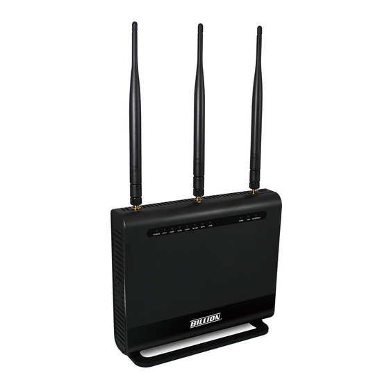
Hardware Specifications Physical Interface • WLAN antennas: 3 external antennas for 5G and 2 internal antennas for 2.4G • DSL: VDSL/ADSL port • Ethernet: 5-port 10/100/1000Mbps auto-crossover (MDI / MDI-X) Switch • EWAN: 1 Gigabit Ethernet port (port#5) for connecting directly to Fiber/ xDSL/ Cable modem, also serving as a Ethernet port#5 when not in EWAN use. -
Page 13: Chapter 2: Installing The Router
Chapter 2: Installing the Router Package Contents • BiPAC 8700AX(L)-1600 Triple-WAN Wireless 1600Mbps 3G/4G LTE (VPN) VDSL2/ADSL2+ Firewall Router • Vertical Stand • Quick Start Guide • CD containing the on-line manual • Three detachable external Wi-Fi Antennas for 5G •... -
Page 14: Important Note For Using This Router
Important note for using this router 1. Do not use the router in high humidity or high temperatures. 2. Do not use the same power source for the router as other equipment. 3. Do not open or repair the case yourself. If the router is too hot, turn off the power immediately and have it repaired at a qualified service center. -
Page 15: Device Description
Device Description The Front LEDs Status Meaning Boot failure or in emergency mode POWER Green System ready Green Successfully connected to a LAN device LAN1~4 Data being transmitted / received Green Wireless enabled (either 2.4G or 5G wireless). WLAN(2.4G / 5G) Blinking Data being transmitted / received. -
Page 16: The Rear Ports
The Rear Ports... - Page 17 Port Meaning POWER Connect the supplied Power Adapter to this port. Power ON/OFF switch ON/OFF Connect to Fibre/ Cable/ xDSL Modem with a RJ-45 cable, for Gigabit broadband connectivity * Note: this port is a LAN/WAN configurable port. Connect a STP Ethernet cable to one of the four LAN ports when connecting to a PC or an office/home network of 10Mbps /100Mbps LAN1~4 /1000Mbps...
-
Page 18: Cabling
Cabling One of the most common causes of problems is bad cabling or ADSL line(s). Make sure that all connected devices are turned on. On the front panel of your router is a bank of LEDs. Verify that the LAN Link and ADSL line LEDs are all lit. If they are not, verify if you are using the proper cables. If the error persists, you may have a hardware problem. -
Page 19: Chapter 3: Basic Installation
Chapter 3: Basic Installation The router can be configured through your web browser. A web browser is included as a standard application in the following operating systems: Linux, Mac OS / Windows 10/ Windows 8, Windows 7 / XP / / Vista, etc. The product provides an easy and user-friendly interface for configuration. Please check your PC network components. -
Page 20: Connecting Your Router
Connecting Your Router Users can connect the VDSL2/ADSL2+ router as the following. DSL mode Broadband mode... - Page 21 3G/4G LTE mode Failover/fallback mode...
-
Page 22: Network Configuration
Network Configuration Configuring a PC in Windows 7/ 8/ 10 For Windows 7/8, go to Start. Click on Control Panel. For Windows 10, Users can click Start then click on Settings; or right click the mouse when it points at Windows ICON (Start), then click Control Panel. - Page 23 IPv4: Select Internet Protocol Version 4 (TCP/IPv4) then click Properties TCP/IPv4 properties window, select the Obtain an IP address automatically Obtain DNS Server address radio buttons. automatically Then click OK to exit the setting. Click OK again in the Local Area Connection Properties window apply...
- Page 24 IPv6: 6. Select Internet Protocol Version 6 (TCP/IPv6) then click Properties 7. In TCP/IPv6 properties window, select the Obtain an IPv6 address automatically and Obtain DNS Server address radio buttons. automatically Then click OK to exit the setting. 8. Click OK again in the Local Area Connection Properties window to apply the new configuration.
-
Page 25: Configuring A Pc In Windows Vista
Configuring a PC in Windows Vista 1. Go to Start. Click on Network. 2. Then click on Network and Sharing Center at the top bar. 3. When the Network and Sharing Center window pops up, select and click on Manage network connections on the left window pane. - Page 26 IPv4: 5. Select Internet Protocol Version 4 (TCP/IPv4) then click Properties. 6. In TCP/IPv4 properties window, select the Obtain an IP address automatically Obtain DNS Server address radio buttons. automatically Then click OK to exit the setting. 7. Click OK again in the Local Area Connection Properties window to apply the new configuration.
- Page 27 IPv6: 5. Select Internet Protocol Version 6 (TCP/IPv6) then click Properties. 6. In TCP/IPv6 properties window, select the Obtain an IPv6 address automatically and Obtain DNS Server address radio buttons. automatically Then click OK to exit the setting. 7. Click OK again in the Local Area Connection Properties window to apply the new configuration.
-
Page 28: Configuring A Pc In Windows Xp
Configuring a PC in Windows XP IPv4: 1. Go to Start / Control Panel (in Classic View). In the Control Panel, double-click on Network Connections 2. Double-click Local Area Connection. 3. In the Local Area Connection Status window, click Properties. 4. - Page 29 IPv6: IPv6 is supported by Windows XP, but you should install it first. Act as shown below: 1. On the desktop, Click Start > Run, type cmd, then press Enter key in the keyboard, the following screen appears. 2. Key in command ipv6 install Configuration is OK now, you can test whether it works ok.
-
Page 30: Factory Default Settings
Factory Default Settings Before configuring your router, you need to know the following default settings. Web Interface (Username and Password) Three user levels are provided by this router, namely Administrator, Remote and Local respectively. See Access Control Administrator Username: admin Password: admin Local Username: user... - Page 31 LAN and WAN Port Addresses The parameters of LAN and WAN ports are pre-set in the factory. The default values are shown in the table. IPv4 LAN Port WAN Port IPv4 address 192.168.1.254 Subnet Mask 255.255.255.0 The PPPoE function is enabled to automatically get DHCP server function Enabled...
-
Page 32: Information From Your Isp
Information from your ISP Before configuring this device, you have to check with your ISP (Internet Service Provider) to find out what kind of service is provided. Gather the information as illustrated in the following table and keep it for reference. VPI/VCI, VC / LLC-based multiplexing, Username, Password, Service PPPoE(RFC2516) Name, and Domain Name System (DNS) IP address (it can be... -
Page 33: Easy Sign On (Ezso)
GUI for any detail configuration. This configuration method is usually auto initiated if user is to connect to the internet via Billion's router for the first time. - Page 34 If the DLS line doesn’t synchronize, the page will pop up warning of the DSL connection failure. 3. Wait while the device is configured (DSL synchronized). 4. WAN port configuration is success and next to wireless, if you want skip wireless setting, click Done.
- Page 35 configure the Wireless setting. The 8700AX(L)-1600 supports dual-band wireless, here you can set to activate wireless on which band or both and set the SSID and encryption Key. (1. Leave it empty to disable the wireless security; 2. Fill in the Key, and the encryption mode will be WPA2-PSK/AES). 6.
- Page 36 Ethernet mode 1. Select Ethernet, press Continue to go on to next step. 2. Enter the username, password from your ISP, for IP and DNS settings, also refer to your ISP. Here IPv6 service is enabled by default. 3. Wait while the device is configured. 4.
- Page 37 5. After the configuration is successful, click Next to Wireless button and you may proceed to configure the Wireless setting. The 8700AX(L)-1600 supports dual-band wireless, here you can set to activate wireless on which band or both and set the SSID and encryption Key (1.
- Page 38 3G/4G LTE 1. Select 3G/4G LTE, press Continue to go on to next step. 2. Enter the APN, username, password from your ISP, for settings about Authentication method, PIN, etc, also refer to your ISP. 3. Wait while the device is configured. 4.
- Page 39 5. After the configuration is successful, click Next to Wireless button and you may proceed to configure the Wireless setting. The 8700AX(L)-1600 supports dual-band wireless, here you can set to activate wireless on which band or both and set the SSID and encryption Key (1.
-
Page 40: Chapter 4: Configuration
Chapter 4: Configuration Configuration via Web Interface Open your web browser; enter the IP address of your router, which by default is 192.168.1.254, and click or press ‘Enter’ key on the keyboard, a login prompt window will appear. The default root username and password are “admin”... - Page 41 Once you have logged on to your BiPAC 8700AX(L)-1600 Router via your web browser, you can begin to set it up according to your requirements. On the configuration homepage, the left navigation pane links you directly to the setup pages, which include: Status (Summary, WAN, Statistics, Bandwidth Usage, 3G/4G LTE Status, Route, ARP, DHCP, VPN, Log) Quick Start (Quick Start)
-
Page 42: Status
Status This Section gives users an easy access to the information about the working router and access to view the current status of the router. Here Summary, WAN, Statistics, Bandwidth Usage, 3G/4G DHCP , VPN subsections are included. Status, Route, ARP,... -
Page 43: Summary
Summary The basic information about the device is provided here (the following is a configured screenshots to let users understand clearly). Device Information Model Name: Displays the model name. Host Name: Displays the name of the router. System Up-Time: Displays the elapsed time since the device is on. Date/Time: Displays the current exact date and time. -
Page 44: Wan
This table displays the information of the WAN connections, users can turn here for WAN connection information. Interface: The WAN connection interface. Description: The description of this connection. Type: The protocol used by this connection. Status: To disconnect or connect the link. Connection Time: The WAN connection time since WAN is up. -
Page 45: Statistics
Statistics The table shows the statistics of LAN. P5 is a configurable WAN/LAN port. Note: Interface: List each LAN interface. P1-P4 indicates the LAN interfaces (P5/WAN can work as a LAN port). Bytes: Display the total Received and Transmitted traffic statistics in Bytes for each interface. Packets: Display the total Received and Transmitted traffic statistics in Packets for each interface. -
Page 46: Wan Service
WAN Service The table shows the statistics of WAN. Interface: Display the connection interface. Description: The description for the connection. Bytes: Display the Received and Transmitted traffic statistics in Bytes for every WAN interface. Packets: Display the Received and Transmitted traffic statistics in Packests for every WAN interface. Errors: Display the statistics of errors arising in Receiving or Transmitting data for every WAN interface. -
Page 47: Xdsl
In ASM Cells: Number of ASM cells received. Out ASM Cells: Number of ASM cells transmitted. In Packet Errors: Number of received packets with errors. In Cell Errors: Number of received cells with errors. Reset: Click to reset the statistics. xDSL Mode: Modulation protocol, including G.dmt, G.lite, T1.413, ADSL2, AnnexL, ADSL2+ and AnnexM. - Page 48 Line Coding (Trellis): Trellis on/off. SNR Margin (dB): Show the Signal to Noise Ratio(SNR) margin. Attenuation (dB): This is estimate of average loop attenuation of signal. Output Power (dBm): Show the output power. Attainable Rate (Kbps): The sync rate you would obtain. Rate (Kbps): Show the downstream and upstream rate in Kbps.
- Page 49 Select the Tested Time(sec), press Start to start test. When it is OK, the following test result window will appear. You can view the quality of ADSL connection. Here the connection is OK. Reset: Click this button to reset the statistics.
-
Page 50: Bandwidth Usage
Bandwidth Usage Bandwidth Usage provides users direct view of bandwidth usage with simple diagram. Bandwidth usage shows the use of the bandwidth from two angles: Transmitted and Received, giving users a clear idea of the usage. P5 is a configurable WAN/LAN port (here the example is in broadband WAN mode, p5 Note: working as a WAN port). - Page 51 When you press View WAN Traffic concurrently button, the WAN Bandwidth Usage pops up so that users can view the WAN traffic concurrently.
-
Page 52: Wan Service
WAN Service Press View WAN Transmitted button to change the diagram to the statistics of the WAN Transmitted Bytes. - Page 53 Press View LAN Traffic concurrently button to directly switch to the LAN Bandwidth Usage page to view the LAN traffic concurrently.
-
Page 54: 3G/4G Lte Status
3G/4G LTE Status Status: The current status of the 3G/4G LTE connection. Signal Strength: The signal strength bar and dBm value indicates the current 3G/4G-LTE signal strength. The front panel 3G/4G LTE Signal Strength LED indicates the signal strength as well. Network Name: The name of the 3G/4G LTE network the router is connecting to. -
Page 55: Route
Route Destination: The IP address of destination network. Gateway: The IP address of the gateway this route uses. Subnet Mask: The destination subnet mask. Flag: Show the status of the route. U: Show the route is activated or enabled. H (host): destination is host not the subnet. G: Show that the outside gateway is needed to forward packets in this route. -
Page 56: Arp
This section displays the router’s ARP (Address Resolution Protocol) Table, which shows the mapping of Internet (IP) addresses to Ethernet (MAC) addresses. This is useful as a quick way of determining the MAC address of the network interface of your PCs to use with the router’s Security –... -
Page 57: Dhcp
DHCP The DHCP Table lists the DHCP lease information for all IP addresses assigned by the DHCP server in the device. Host Name: The Host Name of DHCP client. MAC Address: The MAC Address of internal DHCP client host. IP Address: The IP address which is assigned to the host with this MAC address. Expires in: Show the remaining time after registration. -
Page 58: Vpn
VPN status viewing section provides users IPSec, PPTP, L2TP and GRE VPN status. IPSec Name: The IPSec connection name. Active: Display the connection status. Local Subnet: Display the local network. Remote Subnet: Display the remote network. Remote Gateway: The remote gateway address. SA: The Security Association for this IPSec entry. -
Page 59: Pptp
PPTP PPTP Server Name: The PPTP connection name. Enable: Display the connection status with icon. Status: The connection status. Connection Type: Remote Access or LAN to LAN. Peer Network IP: Display the remote (client side) network and subnet mask in LAN to LAN PPTP connection. -
Page 60: L2Tp
L2TP L2TP Server Name: The L2TP connection name. Enable: Display the connection status with icon. Status: The connection status. Connection Type: Remote Access or LAN to LAN. Peer Network IP: Display the remote (client side) network and subnet mask in LAN to LAN L2TP connection. -
Page 61: Openvpn
OpenVPN OpenVPN Server Name: The OpenVPN connection name. Enable: Display the connection status with icon. Status: The connection status. Connection Type: Remote Access or LAN to LAN. Peer Network IP: Display the subnet address of client side in LAN to LAN mode. Server IP: The tunnel virtual IP of server side assigned by server itself. -
Page 62: Gre
Name: The GRE connection name. Enable: Display the connection status with icons. Status: The connection status, connected or disable. Remote Gateway: The IP of remote gateway. Refresh: Click this button to refresh the connection status. -
Page 63: Log
System Log Display system logs accumulated up to the present time. You can trace historical information with this function. And the log policy can be configured in Configure Log section. Refresh: Click to update the system log. Clear: Click to clear the current log from the screen. -
Page 64: Security Log
Security Log Security log displays the message logged about security, like filter messages and some firewall message. You can turn to IP Filtering Outgoing, IP Filtering Incoming, URL Filter to determine if you want to log this information. Also you can turn to Configure Log section below to determine the level to log the message. -
Page 65: Quick Start
Quick Start Quick Start This part allows you to quickly configure and connect your router to internet. DSL mode (ADSL mode, please choose ATM; VDSL, please choose PTM) Here take ADSL for example. Select DSL, press Continue to go on to next step. Enter the username, password from your ISP, for IP and DNS settings;... - Page 66 3. Wait while the device is configured. 4. WAN port configuration is successful. 5. After the configuration is successful, click Next to Wireless button and you may proceed to configure the Wireless setting. The 8700AX(L)-1600 supports dual-band wireless, here you can set to activate wireless on which band or both and set the SSID and encryption Key (1.
- Page 67 7. Success. Go back to Status > Summary for more information.
- Page 68 Ethernet mode 1. Select Ethernet, press Continue to go on to next step. 2. Enter the username, password from your ISP, for IP and DNS settings; also refer to your ISP. Here IPv6 service is enabled by default. 3. Wait while the device is configured. 4.
- Page 69 5. After the configuration is successful, click Next to Wireless button and you may proceed to configure the Wireless setting. The device supports dual-band wireless connections, in Quick Start part, users can only enable or disable the wireless on the band and the exact SSID and encryption (1.
- Page 70 3G/4G LTE 1. Select 3G/4G LTE, press Continue to go on to next step. 2. Select the 3G mode, and enter the APN, username, password from your ISP; and check with your ISP with the authentication method setting. 3. Wait while the device is configured. 4.
- Page 71 5. After the configuration is successful, click Next to Wireless button and you may proceed to configure the Wireless setting. The device supports dual-band wireless connections, in Quick Start part, users can only enable or disable the wireless on the band and the exact SSID and encryption (1.
- Page 72 7. Success. Go back to Status > Summary for more information.
-
Page 73: Configuration
Configuration When you click this item, the column will expand to display the sub-items that will allow you to further configure your router. LAN, Wireless 5G (wl0), Wireless 2.4G (wl1), WAN, System, USB, Tunnel, Security, Quality Service, Wake On LAN. The function of each configuration sub-item is described in the following sections. -
Page 74: Lan - Local Area Network
LAN - Local Area Network A Local Area Network (LAN) is a shared communication system network where many computers are connected. This type of network is area defined and is usually limited to a confined region within a building. Ethernet Parameters Group Name: This refers to the group you set in Interface Grouping section;... - Page 75 IGMP LAN to LAN Multicast: Check to determine whether to support LAN to LAN (Intra LAN) Multicast. If user want to have a multicast data source on LAN side and he wants to get IGMP snooping enabled, then this LAN-to-LAN multicast feature should be enabled. LAN side firewall: Enable to drop all traffic from the specified LAN group interface.
- Page 76 DHCP Server IP Address: Please enter the DHCP Server IP address. Static IP List The specified IP will be assigned to the corresponding MAC Address listed in the following table when DHCP Server assigns IP Addresses to Clients. Press Add to the Static IP List. Enter the MAC Address, IP Address, and then click Apply to confirm your settings.
-
Page 77: Ipv6 Autoconfig
IPv6 Autoconfig The IPv6 address composes of two parts, the prefix and the interface ID. There are two ways to dynamically configure IPv6 address on hosts. One is “stateful” configuration, for example using DHCPv6 (which resembles its counterpart DHCP in IPv4.) In the stateful auto- configuration model, hosts obtain interface addresses and/or configuration information and parameters from a DHCPv6 server. - Page 78 DHCPv6 Server Type: Select Stateless or Stateful. When DHCPv6 is enabled, this parameter is available. Stateless: If selected, the PCs in LAN are configured through RA mode, thus, the PCs in LAN are configured through RA mode, to obtain the prefix message and generate an address using a combination of locally available information (MAC address) and information (prefix) advertised by routers, but they can obtain such information like DNS from DHCPv6 Server.
- Page 79 Stateless and Stateful IPv6 address Configuration Stateless: Two methods can be carried. With DHCPv6 disabled, but Issue Router Advertisement Enabled With this method, the PCs in LAN are configured through RA mode, thus, the PCs in LAN are configured through RA mode, to obtain the prefix message and generate an address using a combination of locally available information (MAC address) and information (prefix) advertised by routers.
- Page 80 Stateful: two methods can be adopted. With only DHCPv6 enabled With this method, the PCs’ addresses are configured the same as in IPv4, that is addresses are assigned by DHCPv6 server. With both DHCPv6 and Issue Router Advertisement Enabled With this method, the PCs’ addresses are configured the same like above, and the address information in RA packets will be neglected.
-
Page 81: Interface Grouping
Interface Grouping Interface grouping is a function to group interfaces, known as VLAN. A Virtual LAN, commonly known as a VLAN, is a group of hosts with the common set of requirements that communicate as if they were attached to the same broadcast domain, regardless of the physical location. A VLAN has the same attributes as a physical LAN, but it allows for end stations to be grouped together even if they are not located on the same network switch. - Page 82 Click Add to add groups. Group Name: Type a group name. Grouped WAN Interfaces: Select from the box the WAN interface you want to applied in the group. Grouped LAN Interfaces: Select the LAN interfaces you want to group as a single group from Available LAN Interfaces.
- Page 83 In group "test", P2 and PPP0.1 are grouped in one group, they have their only network , see LAN. If you want to remove the group, check the box as the following and press Remove. If you like to automatically add LAN clients to a WAN Interface in the new group add the Note: DHCP vendor ID string.
-
Page 84: Wireless 5G(Wl0) & 2.4G(Wl1)
Wireless 5G(wl0) & 2.4G(Wl1) BiPAC 8700AX(L)-1600 is a simultaneous dual-band (2.4G and 5G) wireless router supporting 11b/g/n/a/ac wireless standards. It allows multiple wireless users on 2.4G and 5G radio bands to surf the Internet, checking e-mail, watching video, listening to music over the Internet concurrently. You can choose the optimum radio band wireless connection base on your environment. -
Page 85: Basic
Basic It let you determine whether to enable Wireless function and set the basic parameters of an AP and the Virtual APs. Wireless: Default setting is set to Enable. If you do not have any wireless devices, check the checkbox again to unselect. Hide SSID: It is function in which transmits its SSID to the air so that when wireless client searches for a network, router can then be discovered and recognized. - Page 86 a distinct SSID and capability set. Alternatively, multiple Virtual APs might advertise the same SSID but a different capability set – allowing access to be provided via Web Portal, WEP, and WPA simultaneously. Where APs are shared by multiple providers, Virtual APs provide each provider with separate authentication and accounting data for their users, as well as diagnostic information, without sharing sensitive management traffic or data between providers.
-
Page 87: Security
Security Wireless security prevents unauthorized access or damage to computers using wireless network. Note: The WPS feature will also be unavailable when the security setting is not WPA2 PSK or OPEN. So, if you manually set the wireless security setting, you should give notice to it, but you can find prompt indicating configuration. - Page 88 Shared This is similar to network authentication ‘Open’. But here the WEP Encryption must be enabled. 802.1x RADIUS Server IP Address: RADIUS( Remote Authentication Dial In User Service), Enter the IP address of RADIUS authentication server. RADIUS Server Port: Enter the port number of RADIUS authentication server here. RADIUS Key: Enter the password of RADIUS authentication server.
- Page 89 WPA2 Protected Management Frame: Select whether to enable protected management frame mechanism. By default, it is disabled. If enabled, the network adapter of the attempting wireless client should also support this feature. WPA2 Preauthentication: When a wireless client wants to handoff to another AP, with preauthentication, it can perform 802.1X authentication to the new AP, and when handoff happens, this mode will help reduce the association time.
- Page 90 Mixed WPA2/WPA Protected Management Frame: Select whether to enable protected management frame mechanism. By default, it is disabled. If enabled, the network adapter of the attempting wireless client should also support this feature. WPA2 Preauthentication: When a wireless client wants to handoff to another AP, with preauthentication, it can perform 802.1X authentications to the new AP, and when handoff happens, this mode will help reduce the association time used.
- Page 91 WPS Setup WPS (Wi-Fi Protected Setup) feature is a standard protocol created by Wi-Fi Alliance. WPS is used to exchange the AP setting with Station and configure Ap settings. This feature greatly simplifies the steps needed to create a Wi-Fi network for a residential or an office setting. The commonly known PIN method is supported to configure WPS.
- Page 92 Configure AP as Registrar Add Enrollee with PIN method 1. Select radio button “Enter STA PIN”. 2. Input PIN from Enrollee Station (16837546 in this example), Or else users can alternatively enter the authorized station MAC Help: it is to help users to understand the concept and correct operation.
- Page 93 4. Operate Station to start WPS Adding Enrollee. Launch the wireless client’s WPS utility (eg.Ralink Utility). Set the Config Mode as Enrollee, press the WPS button on the top bar, select the AP (eg. Wlan-ap-2.4g) from the WPS AP List column. Then press the PIN button located on the middle left of the page to run the scan.
- Page 94 4. The client’s SSID and security settings will now be configured to match the SSID and security settings of the registrar. You can check the message in the red ellipse with the security parameters you set, here we all use the default.
- Page 95 Configure AP as Enrollee Add Registrar with PIN Method 1. Set AP to “Unconfigured Mode”.
- Page 96 2. Launch the wireless client’s WPS utility (eg. Ralink Utility). Set the Config Mode as Registrar. Enter the PIN number (10864111 (device) for example) in the PIN Code column then choose the correct AP (eg. wlan-ap-2.4g) from the WPS AP List section before pressing the PIN button to run the scan.
- Page 97 3. The router’s (AP’s) SSID and security setting will now be configured to match the SSID and security setting of the registrar. 4. Do Web Page refresh after ER complete AP Configuration to check the new parameters setting.
-
Page 98: Mac Filter
MAC Filter Select SSID: select the SSID you want this filter applies to. MAC Restrict Mode: Disable: disable the MAC Filter function. Allow: allow the hosts with the following listed MACs to access the wireless network. Deny: deny the hosts with the following listed MACs to access the wireless network. Click Add to add the MACs. -
Page 99: Wireless Bridge
Wireless Bridge WDS (wireless distributed system) is a system enabling the wireless interconnection of access points. It’s easy to install, simply define the peer’s MAC address of the connected AP. WDS takes advantage of cost saving and flexibility with no extra wireless client device required to bridge between two access points and extending an existing wired or wireless infrastructure network to create a larger network. - Page 100 Example: How to set up WDS/Wireless Bridge Before setting up WDS: 1). The router involved should all support WDS/Wireless Bridge feature. 2). To ensure better compatibility, please use the router of the same brand, or better the same model. Point to Point wireless bridge Router B needs to bridge to Router A using wireless bridge for internet access and wireless coverage extension.
- Page 101 2). Configure WAN Interface for Router A (ADSL PPPoE). See Service. 3). Configure wireless for Router A (SSID, Country, Security, Channel.) I. Basic configuration (SSID, Country, etc) II. Wireless security configuration for Router A. Configure Network Authentication as WPA2-PSK and WPA/WAPI passphrase as 1234567890. (Users configure wireless security parameters according to their own needs.
- Page 102 III. Advanced wireless configuration for Router A (Channel 1, Bandwidth 20MHz/40MHz , OBSS Coexistence Disable ). Note: Select your own bandwidth, but both sides need to be same.
- Page 103 4). Configure Wireless Bridge for Router A, by scanning or inputting Router B’s wireless MAC address. Make sure you know Router B’s wireless MAC. If not, go to Wireless > Basic. Check BSSID which is Router B’s wireless MAC. (Router B’s wireless basic configuration) WDS Configuration finished for Router A.
- Page 104 Router B setup 1). Login to Router B (LAN IP Address: 192.168.1.1. Here if the LAN is same with router A, please change it to 192.168.1.X which needs to be on the same subnet with router A), disable DHCP server. 2).
- Page 105 II. Wireless security configuration for Router B. Configure Network Authentication the same as Router A. III. Advanced wireless configuration for Router B, the same as set in Router A (Channel 1, Bandwidth 20MHz/40MHz , OBSS Coexistence Disable ).
- Page 106 3). Configure Wireless Bridge for Router B, by scanning or inputting Router A’s wireless MAC address. Make sure you know Router A’s wireless MAC. If not, go to Wireless > Basic. Check BSSID which is A’s wireless MAC. (Router A’s wireless basic configuration) WDS Configuration finished for Router B.
- Page 107 One-to-Multiple wireless bridge Router B and C need to bridge to Router A using wireless bridge for internet access and wireless coverage extension. Router B and C share the same Wireless SSID, Country, Security, Channel setting with Router A.
- Page 108 Router A setup 1). Login to Router A (LAN IP Address: 192.168.1.254), enable DHCP server. 2). Configure WAN Interface for Router A (ADSL PPPoE). See Service.
- Page 109 3). Configure wireless for Router A (SSID, Country, Security, Channel.) I. Basic configuration (SSID, Country, etc) II. Wireless security configuration for Router A. Configure Network Authentication as WPA2-PSK and WPA/WAPI passphrase as 1234567890. (Users configure wireless security parameters according to their own needs. )
- Page 110 III. Advanced wireless configuration for Router A (Channel 1, Bandwidth 20MHz/40MHz , OBSS Coexistence Disable ) Note: Select your own bandwidth, but all sides need to be same.
- Page 111 4). Configure Wireless Bridge for Router A, by scanning or inputting Router B and C’s wireless MAC addresses. Make sure you know Router B and C’s wireless MACs. If not, go to Wireless > Basic. Check BSSID which is Router B’s wireless MAC. Router B for example (Router B’s wireless basic configuration) WDS Configuration finished for Router A.
- Page 112 Router B setup 1). Login to Router B (LAN IP Address: 192.168.1.1. Here if the LAN is same with router A, please change it to 192.168.1.X which needs to be on the same subnet with router A), disable DHCP server. 2).
- Page 113 II. Wireless security configuration for Router B. Configure Network Authentication the same as Router A. III. Advanced wireless configuration for Router B, the same as set in Router A (Channel 1, Bandwidth 20MHz/40MHz , OBSS Coexistence Disable ).
- Page 114 3). Configure Wireless Bridge for Router B, by scanning or inputting Router A’s wireless MAC address. Make sure you know Router A’s wireless MAC. If not, go to Wireless > Basic. Check BSSID which is A’s wireless MAC. (Router A’s wireless basic configuration) WDS Configuration finished for Router B.
- Page 115 Router C setup Refer to Router B setup...
-
Page 116: Advanced
Advanced – 2.4GHz Wireless Band: In the 2.4 GHz radio frequency. Channel: Choose a channel to use. Here is a list of available channels or select Auto mode instead. Scan Used Channel: Press the button to scan and list all channels being used. Auto Channel Timer (min): Available when Auto Channel is selected. - Page 117 operating at 802.11n speeds. RIFS Advertisement: Reduced Inter-frame Spacing (RIFS) is an 802.11n feature that also improves performance by reducing the amount of dead time required between OFDM transmissions. Select Off to disable this function or auto to enable this function. OBSS Co-Existence: coexistence (or not) between 20 MHZ and 40 MHZ overlapping basic service sets (OBSS) in wireless local area networks.
- Page 118 – 5GHz Wireless Band: In the 5GHz radio frequency. Channel: Choose a channel to use. Here is a list of available channels or select Auto mode instead. Scan Used Channel: Press the button to scan and list all channels being used. Auto Channel Timer (min): Available when Auto Channel is selected.
- Page 119 802.11n Rate: This allows you to select the fixed transmission rate or auto. 802.11n Protection: turn off for maximize throughput. Support 802.11n Client Only: turn on the option to only provide wireless access to the clients operating at 802.11n speeds. RIFS Advertisement: Reduced Inter-frame Spacing (RIFS) is an 802.11n feature that also improves performance by reducing the amount of dead time required between OFDM transmissions.
- Page 120 check for radar on a channel before the Access Point establishes a wireless network with the channel. In-Network Radar Check (Used for 802.11h only): After the wireless network got established, specifies a period of time in seconds [10-99] to check for radar when switching to another non-radar channel.
-
Page 121: Station Info
Station Info Here you can view information about the wireless clients. MAC Address: The MAC address of the wireless clients. Associated: List all the stations that are associated with the Access Point. If a station is idle for too long, it is removed from this list Authorized: List those devices with authorized access. -
Page 122: Schedule Control
Schedule Control Schedule control is aimed to offer methods to flexibly control when the wireless network (SSID) is allowed for access. The Wireless schedule only functions whilst Wireless is enabled. The Guest/Virtual AP schedule control only operates whilst the associated AP is enabled. For detail setting the timeslot, user can turn to Time Schedule Time Schedule: Set when the SSID works. -
Page 123: Wan-Wide Area Network
WAN-Wide Area Network A WAN (Wide Area Network) is a computer network that covers a broad geographical area (eg. Internet) that is used to connect LAN and other types of network systems. WAN Service Three WAN interfaces are provided for WAN connection: DSL (VDSL/ADSL), Ethernet and 3G/4G LTE. - Page 124 Layer2 Interface: 2 transfer mode, ATM (ADSL) or PTM (VDSL). PPPoE PPPoE (PPP over Ethernet) provides access control in a manner which is similar to dial-up services using PPP. VPI/VCI: Enter the VPI/VCI combination from you ISP.
- Page 125 Encapsulation Mode: Select the encapsulation mode, LLC/SNAP-BRIDGING, or VC/MUX. Description: User-defined description for the connection, commonly for friendly use. 802.1P Priority: The parameter indicates the frame priority level from 0 (lowest) to 7 (highest), which can be used to prioritize different classes of traffic (voice, video, data, etc). Enter the priority identification, tagged: 0-1, untagged: -1.
- Page 126 MLD Multicast Proxy: check whether to enable this function. MLD (Multicast Listener Discovery Protocol) Proxy intercepts the MLD request from Clients a set up the multicast-forwarding table. it takes over some of the router’s job, simplifying the router’s job and multicast communication. Support MLDv1 and MLDv2.
- Page 127 Click Next to continue to set the default gateway and DNS for IPv4 and IPv6. Default Gateway Select default gateway for you connection (IPv4 and IPv6). IPv4 Three ways to set an IPv4 DNS server Available WAN interfaces: Select a desirable WAN interface as the IPv4 DNS server. Static DNS Address: To specify DNS server manually by entering your primary and secondary DNS server addresses.
- Page 128 If you don’t need a service, select the item you want to remove, check the checkbox, then press Remove. Press Edit button to re-edit this service settings. Here you can configure WAN Service, if it is OK, you can access the internet. You can go to Status >WAN or Summary to view the WAN connection information (if your ISP provides IPv6 service, then you will obtain an IPv6 address).
- Page 129 PPPoA VPI/VCI: Enter the VPI/VCI combination from you ISP. Encapsulation Mode: Select the encapsulation mode, LLC/SNAP-BRIDGING, or VC/MUX. Description: User-defined description for the connection. Username: Enter the account obtained from the ISP. Password: Enter the password obtained from the ISP. Authentication Method: Default is Auto.
- Page 130 useful when saving internet fees. Inactivity Timeout: The set Inactivity timeout period, unit: minutes. It is combined use with Dial on Demand, users should specify the concrete time interval for dial on demand. IPv6 for this service: Enable to use IPv6 service. IPv6 Address: Select whether to set static IPv6 address or obtain automatically.
- Page 131 IP over Ethernet VPI/VCI: Enter the VPI/VCI combination from you ISP. Encapsulation Mode: Select the encapsulation mode, LLC/SNAP-BRIDGING, or VC/MUX. Description: User-defined description for the connection, commonly for friendly use. Authentication Method: Default is Auto. Or else your ISP will advise you the appropriate mode. 802.1P Priority: The parameter indicates the frame priority level from 0 (lowest) to 7 (highest), which can be used to prioritize different classes of traffic (voice, video, data, etc).
- Page 132 string of n octets, interpreted by servers. Vendors may choose to define specific vendor class identifiers to convey particular configuration or other identification information about a client. Option 77 User ID: Set the User ID, which identifies the request DHCP user. Option 61 Client ID: Set the client ID., which identifies the request DHCP client.
- Page 133 MTU: Maximum Transmission Unit, the size of the largest datagram (excluding media-specific headers) that IP will attempt to send through the interface. MAC Spoofing: This option is required by some service providers specifying some specific MAC allowed for joining network. You must fill in the MAC address specified by your service provider when this information is required.
- Page 134 IPoA VPI/VCI: Enter the VPI/VCI combination from you ISP. Encapsulation Mode: Select the encapsulation mode, LLC/SNAP-BRIDGING, or VC/MUX. Description: User-defined description for the connection, commonly for friendly use. WAN gateway IP Address: Enter your gateway IP address to the device provided by your ISP. NAT: The NAT (Network Address Translation) feature allows multiple users to access the Internet through a single IP account by sharing the single IP address.
- Page 135 Bridging VPI/VCI: Enter the VPI/VCI combination from you ISP. Encapsulation Mode: Select the encapsulation mode, LLC/SNAP-BRIDGING, or VC/MUX. Description: User-defined description for the connection, commonly for friendly use. 802.1P Priority: The parameter indicates the frame priority level from 0 (lowest) to 7 (highest), which can be used to prioritize different classes of traffic (voice, video, data, etc).
-
Page 136: Ethernet
Ethernet Ethernet WAN connection is well known as directly broadband WAN connection. PPPoE Description: User-defined description for the connection, commonly for friendly use. 802.1P Priority: The parameter indicates the frame priority level from 0 (lowest) to 7 (highest), which can be used to prioritize different classes of traffic (voice, video, data, etc). Enter the priority identification, tagged: 0-1, untagged: -1. - Page 137 identification, tagged: 0-4094, untagged : -1. Username: Enter the account obtained from the ISP. Password: Enter the password obtained from the ISP. Service Name: The item is for identification purpose, user can define it yourselfe. Authentication Method: Default is Auto. Or else your ISP will advise you the appropriate mode. Firewall: Enable to drop all traffic from WAN side.
- Page 138 Click Next to continue to set the default gateway and DNS for IPv4 and IPv6. Default Gateway Select default gateway for you connection (IPv4 and IPv6). IPv4 Three ways to set an IPv4 DNS server Available WAN interfaces: Select a desirable WAN interface as the IPv4 DNS server. Static DNS Address: To specify DNS server manually by entering your primary and secondary DNS server addresses.
- Page 139 If you don’t need the service, select the item you want to remove, check the checkbox, then press Remove, it will be OK. Press Edit button to re-edit this service settings. Here the corresponding WAN Service have been configured, if it is OK, you can access the internet. You can go to Status>WAN or Summary to view the WAN connection information (if your ISP provides IPv6 service, then you will obtain an IPv6 address).
- Page 140 IP over Ethernet Description: User-defined description for the connection, commonly for friendly use. 802.1P Priority: The parameter indicates the frame priority level from 0 (lowest) to 7 (highest), which can be used to prioritize different classes of traffic (voice, video, data, etc). Enter the priority identification, tagged: 0-1, untagged: -1.
- Page 141 Default setting is Disable. Option 50 Request IP Address: Set the particular request IP address to be assigned from the DHCP. Option 51 Request Leased Time: Set the request lease time for the requested IP address. Option 54 Request Server Address: Set request Server Address. WAN IP Address: Enter your IPv4 address to the device provided by your ISP.
- Page 142 Bridging Description: User-defined description for the connection, commonly for friendly use. 802.1P Priority: The parameter indicates the frame priority level from 0 (lowest) to 7 (highest), which can be used to prioritize different classes of traffic (voice, video, data, etc). Enter the priority identification, tagged: 0-1, untagged: -1.
-
Page 143: 3G/4G Lte
3G/4G LTE Select 3G/4G LTE to configure the route to enjoy the mobility. By default the 3G/4G LTE interface is on, user can edit the parameters to meet your own requirements. Click Edit button to enter the 3G/4G LTE configuration page. Dial on demand: If enabled, the 3G/4G LTE will work in dial on demand mode and be brought up only when there is no active default route. - Page 144 preferred, UMTS 3G preferred, Automatic, and Use 3G/LTE 3g dongle settings. If you are uncertain what services are available to you, and then please select Automatic. TEL No.: The dial string to make a 3G/LTE user internetworking call. It may provide by your mobile service provider.
- Page 145 secondary DNS server addresses. Parental Controls: If user registers and gets a DNS account in the parental control provider website, expecting to enjoy a more reliable and safer internet surfing environment, please select this option (need to configure at Parental Control Provider).
-
Page 146: Failover
Failover Auto failover/failback is to ensure an always-on internet connection. Users can set a Master WAN interface (main WAN) and a slave interface (backup WAN), and when Master WAN fails, it will switch to slave WAN, and when master WAN restores, it will switch to master WAN interface again. L3 WAN Failover: Check Enable to activate L3 WAN failover. -
Page 147: Dsl
This screen allows you to set DSL parameters. DSL knowledge is required to configure these settings. Contact your ISP to make sure that these parameters are correct. Modulation: There are 8 modes “G.Dmt”, “G.lite”, “T1.413”, “ADSL2”, “AnnexL”, ”ADSL2+”, “AnnexM”, “VDSL2” that user can select for this connection. Profile: VDSL profiles up to 17a. -
Page 148: Snr
Signal-to-noise ratio (often abbreviated SNR or S/N) is a measure used in science and engineering that compares the level of a desired signal to the level of background noise. It is defined as the ratio of signal power to the noise power. SNR: Change the value to adjust the DSL link rate, more suitable for an advanced user. -
Page 149: System
System Internet Time The router does not have a real time clock on board; instead, it uses the Network Time Protocol (NTP) to get the most current time from an NTP server. NTP is a protocol for synchronization of computers. It can enable computers synchronize to the NTP server or clock source with a high accuracy. -
Page 150: Firmware Upgrade
Firmware Upgrade Software upgrading lets you experience new and integral functions of your router. Restart device with: Factory Default Settings: Restart the device with factory default settings automatically when finishing upgrading. Current Settings: Restart the device with the current settings automatically when finishing upgrading. -
Page 151: Backup / Update
Backup / Update These functions allow you to save and backup your router’s current settings to a file on your PC, or to restore from a previously saved backup. This is useful if you wish to experiment with different settings, knowing that you have a backup handy in the case of any mistakes. It is advisable to backup your router’s settings before making any significant changes to your router’s configuration. -
Page 152: Access Control
Access Control Access Control is used to prevent unauthorized access to the router configuration page. Here you can change the login user password. Three user levels are provided here. Each user level there’s a default provided user. You must access the router with the appropriate username and password. Here the corresponding passwords are allowed to change. -
Page 153: Mail Alert
Mail Alert Mail alert is designed to keep system administrator or other relevant personnel alerted of any unexpected events that might have occurred to the network computers or server for monitoring efficiency. With this alert system, appropriate solutions may be tackled to fix problems that may have arisen so that the server can be properly maintained. -
Page 154: Sms Alert
SMS Alert SMS, Short Message Service, is to inform clients the information clients subscribe. The BiPAC 8700AX(L)-1600 offers SMS alert sending clients alert messages when a WAN IP change is detected. Recipient’s Number (WAN IP Change Alert): Enter the Recipient’s number that will receive the alert message once a WAN IP change has been detected. -
Page 155: Configure Log
Configure Log Log: Enable or disable this function. Log level: Select your log level. The log level allows you to configure which types of events are logged. There are eight log levels from high to low are displayed below: Emergency = system is unusable Alert = action must be taken immediately Critical = critical conditions Error = error conditions... -
Page 156: Usb
Storage here refers to network sharing in the network environment. USB devices act as the storage carrier for common file sharing, DLNA. With a USB-based printer, the 8700AX(L)-1600 can also serve as a network printer offering printing service for every client on the network. Storage Device Info This part provides users direct access to the storage information like the total volume, the used and the remaining capacity of the device. -
Page 157: User Account
User Account Users here can add user accounts for access to the storage, in this way users can access the network sharing storage with the specified account, and again protect their own data. Default user admin. Click Add button, enter the user account-adding page: Username: user-defined name, but simpler and more convenient to remember would be favorable. - Page 158 Accessing mechanism of Storage: In your computer, Click Start > Run, enter \\192.168.1.254...
- Page 159 When accessing the network storage, you can see a folder named “public”, users should have the account to enter, and the account can be set at the User Accounts section. When first logged on to the network folder, you will see the “public” folder. Public: The public sharing space for each user in the USB Storage.
- Page 160 Access the folder public.
- Page 161 When successfully accessed, the private folder of each user is established, and user can see from the following picture. The test fold in the picture is the private space for each user.
-
Page 162: Print Server
Print Server The Print Server feature allows you to share a printer on your network by connecting a USB cable from your printer to the USB port on the 8700AX(L)-1600 This allows you to print from any location on your network. Only USB printers are supported Note: Setup of the printer is a 3 step process (8700AX-1600 for example) - Page 163 Step 2: Click ‘’Add a Printer’’. Step 3: Click “Add a network, wireless or Bluetooth printer...
- Page 164 Step 4: Click “The printer that I want isn’t listed” Step 5: Select “Select a shared printer by name” Enter http://8700AX-1600 - LAN-IP:631/printers/printer-name or. Make sure printer’s name is the same as what you set in the 8700AX earlier For Example: http://192.168.1.254:631/printers/OfficePrinter OfficePrinter is the Printer Name we set up earlier...
- Page 165 Step 6: Click “Next” to add the printer driver. If your printer is not listed and your printer came with an installation disk, click “Have Disk” find it and install the driver. Step 7: Click “Next”...
- Page 166 Step 8: Click “Next” and you are done You will now be able to see your printer on the Devices and Printers Page...
-
Page 167: Dlna
DLNA The Digital Living Network Alliance (DLNA) is a non-profit collaborative trade organization established by Sony in June 2003, which is responsible for defining interoperability guidelines to enable sharing of digital media between consumer devices such as computers, printers, cameras, cell phones and other multiple devices. - Page 168 Take Windows media player in Windows 7 accessing the DLNA server for example for usage of DLNA .
-
Page 169: Ip Tunnel
IP Tunnel An IP Tunnel is an Internet Protocol (IP) network communication channels between two networks of different protocols. It is used to transport another network protocol by encapsulation of its packets. IP Tunnels are often used to connect two disjoint IP networks that do not have a native routing path to each other, via an underlying routable protocol across an intermediate transport network, like VPN. - Page 170 packets from/to the WAN interface, the tunnel would be used to transport the packets. Associated LAN Interface: Set the linked LAN interface with the tunnel. Method: 6rd operation mechanism: manually configured or automatically configured. If manually, please fill out the following 6rd parameters. V4 Common Bit Length: Specify the length of IPv4 address carried in IPv6 prefix, for example, 0 means to carry all the 32 bits of IPv4 address while 8 carries 24 bits of the IPv4 address.
-
Page 171: Ipv4Inipv6
IPv4inIPv6 4in6 refers to tunneling of IPv4 in IPv6. It is an inherent internet interoperation mechanism allowing IPv4 to be used in an IPv6 only network. 4in6 uses tunneling to encapsulate IPv4 traffic over configured IPv6 tunnels. 4in6 tunnels are usually manually configured but they can be automated using protocols such as TSP to allow easy connection to a tunnel broker. -
Page 172: Security
Security IP Filtering Outgoing IP filtering enables you to configure your router to block specified internal/external users (IP address) from Internet access, or you can disable specific service requests (Port number) to /from Internet. The relationship among all filters is “or” operation, which means that the router checks these different filter rules one by one, starting from the first rule. - Page 173 65535. Time Schedule: Select or set exactly when the rule works. When set to “Always On”, the rule will work all time; and also you can set the precise time when the rule works, like 01:00 - 19:00 from Monday to Friday. Or you can select the already set timeslot in “Time Schedule” during which the rule works.
- Page 174 How to disable set rule. (Rule inactive)
-
Page 175: Ip Filtering Incoming
IP Filtering Incoming Incoming IP Filtering is set by default to all incoming traffic, but user can set rules to block forward the specific incoming traffic. Note: 1. The maximum number of entries: 32. 2. When LAN side firewall or firewall in WAN interface(s) is enabled, user can move here to add allowing rules to pass through the firewall. - Page 176 Time Schedule: Select or set exactly when the rule works. When set to “Always On”, the rule will work all time; and also you can set the precise time when the rule works, like 01:00 - 19:00 from Monday to Friday. Or you can select the already set timeslot in “Time Schedule” during which the rule works.
-
Page 177: Mac Filtering
MAC Filtering MAC Filtering is only effective on ATM PVCs configured in Bridged mode. FORWARDED means that all MAC layer frames will be forwarded except those matching with any of the specified rules in the following table. BLOCKED means that all MAC layer frames will be blocked except those matching with any of the specified rules in the following table. -
Page 178: Blocking Wan Ping
Blocking WAN PING This feature is enabled to let your router not respond to any ping command when someone others “Ping” your WAN IP. -
Page 179: Time Restriction
Time Restriction A MAC (Media Access Control) address is the unique network hardware identifier for each PC on your network’s interface (i.e. its Network Interface Card or Ethernet card). Using your router’s MAC Address Filter function, you can configure the network to block specific machines from accessing your LAN during the specified time. - Page 180 An example: Here you can see that the user “child-use” with a MAC of 18:a9:05:04:12:23 is blocked to access the router from 00:00 to 23:59 Monday through Friday. The “test” can access the internet always. If you needn’t this rule, you can check the box, press Remove, it will be OK.
-
Page 181: Url Filter
URL Filter URL (Uniform Resource Locator – e.g. an address in the form of http://www.abcde.com or http://www.example.com) filter rules allow you to prevent users on your network from accessing particular websites by their URL. There are no pre-defined URL filter rules; you can add filter rules to meet your requirements. - Page 182 Keywords Filtering Maximum number of entries: 32. Note: Click to add the keywords. Enter the Keyword, for example image, and then click Add. You can add other keywords like this. The keywords you add will be listed as above. If you want to reedit the keyword, press the Edit radio button left beside the item, and the word will listed in the Keyword field, edit, and then press Edit/Delete to confirm.
- Page 183 Filtering. Except IP Address In the section, users can set the exception IP respectively for IPv4 and IPv6. Click to add the IP Addresses. Enter the except IP address. Click Add to save your changes. The IP address will be entered into the Exception List, and excluded from the URL filtering rules in effect.
-
Page 184: Parental Control Provider
Parental Control Provider Parental Control Provider provides Web content filtering offering safer and more reliable web surfing for users. Please get an account and configure at the selected Provider “www.opendns.com” in advance. To use parental control (DNS), user needs to configure to use parental control (DNS provided by parental control provider) to access internet at WAN configuration or DNS page(See DNS). -
Page 185: Qos - Quality Of Service
QoS - Quality of Service Quality of Service QoS helps you to control the data upload traffic of each application from LAN (Ethernet) to WAN (Internet). This feature allows you to control the quality and speed of throughput for each application when the system is running with full upstream load. - Page 186 Protocol: Select the supported protocol from the drop down list. DSCP Marking: Differentiated Services Code Point (DSCP), it is the first 6 bits in the ToS byte. DSCP Marking allows users to classify the traffic of the application to be executed according to the DSCP value.
- Page 187 Internal IP Address: The IP address values for Local LAN devices you want to give control. Internal Port: The Port number on the LAN side, it is used to identify an application. External IP Address: The IP address on remote / WAN side. External Port: The Port number on the remote / WAN side.
- Page 188 Examples: Common usage 1. Give outgoing VoIP traffic more priority. The default queue priority is normal, so if you have VoIP users in your local network, you can set a higher priority to the outgoing VoIP traffic. 2. Give regular web http access a limited rate...
- Page 189 3. If you are actively engaged in P2P and are afraid of slowing down internet access for other users within your network, you can then use QoS to set a rule that has low priority. In this way, P2P application will not congest the data transmission with other applications. Other applications, like FTP, Mail access, users can use QoS to control based on need.
-
Page 190: Qos Port Shaping
QoS Port Shaping QoS port shaping supports traffic shaping of Ethernet interfaces. It forcefully maximizes the throughput of the Ethernet interface. When “Shaping Rate” is set to “-1”, no shaping will be in place and the “Burst Size” is to be ignored. Interface: P1-P5. -
Page 191: Nat
NAT (Network Address Translation) feature translates a private IP to a public IP, allowing multiple users to access the Internet through a single IP account, sharing the single IP address. It is a natural firewall for the private network. Exceptional Rule Group Exceptional Rule is dedicated to giving or blocking NAT/DMZ access to some specific IP or IPs(range). -
Page 192: Virtual Servers
Virtual Servers In TCP/IP and UDP networks a port is a 16-bit number used to identify which application program (usually a server) incoming connections should be delivered to. Some ports have numbers that are pre-assigned to them by the IANA (the Internet Assigned Numbers Authority), and these are referred to as “well-known ports”. - Page 193 The following configuration page will appear to let you configure. Interface: Select from the drop-down menu the interface you want the virtual server(s) to apply. WAN IP: To specify the exact WAN IP address. It can be flexible while there are multiple WAN IPs on one interface.
- Page 194 access to a group of IPs. For example, as we set previously group 1 blocking access to 172.16.1.102-172.16.1.106. If here you want to block Virtual Server access to this IP range, you can select Group1. Set up 1. Select a Server Name from the drop-down menu, then the port will automatically appear, modify some as you like, or you can just leave it as default.
- Page 195 Means the rule is inactive) Remove If you don’t need a specified Server, you can remove it. Check the check box beside the item you want to remove, then press Remove, it will be OK.
-
Page 196: Dmz Host
DMZ Host The DMZ Host is a local computer exposed to the Internet. When setting a particular internal IP address as the DMZ Host, all incoming packets will be checked by Firewall and NAT algorithms before being passed to the DMZ host, when a packet received does not use a port number used by any other Virtual Server entries. -
Page 197: One-To-One Nat
One-to-One NAT One-to-One NAT maps a specific private/local address to a global/public IP address. If user has multiple global/public IP addresses from your ISP, you are free to use one-to-one NAT to assign some specific public IP for an internal IP like a public web server mapped with a global/public IP for outside access. -
Page 198: Port Triggering
Port Triggering Port triggering is a way to automate port forwarding with outbound traffic on predetermined ports (‘triggering ports’), incoming ports are dynamically forwarded to the initiating host, while the outbound ports are in use. Port triggering triggers can open an incoming port when a client on the local network makes an outgoing connection on a predetermined port or a range of ports. - Page 199 Open port Start: Enter a port number as the open port staring number. End: Enter a port number as the open port ending number. Any port in the range delimited by the ‘Start’ and ‘End’ would be the preset forwarding port or open port.
- Page 200 Edit/Remove If you don’t need a specified Server, you can remove it. Check the check box beside the item you want to remove, and then press Remove. Click Edit to re-edit your port-triggering rule.
-
Page 201: Alg
The ALG Controls enable or disable protocols over application layer. SIP: Enable the SIP ALG when SIP phone needs ALG to pass through the NAT. Disable the SIP when SIP phone includes NAT-Traversal algorithm. H.323: Enable to secure the voice communication using H.323 protocol when one or both terminals are behind a NAT. -
Page 202: Wake On Lan
Wake On LAN Wake on LAN (WOL, sometimes WoL) is an Ethernet computer networking standard that allows a computer to be turned on or woken up remotely by a network message. Host Label: Enter identification for the host. Select: Select MAC address of the computer that you want to wake up or turn on remotely. Wake by Schedule: Enable to wake up your set device at some specific time. -
Page 203: Vpn
A virtual private network (VPN) is a private network that interconnects remote (and often geographically separate) networks through primarily public communication infrastructures such as the Internet. VPNs provide security through tunneling protocols and security procedures such as encryption. For example, a VPN could be used to securely connect the branch offices of an organization to a head office network through the public Internet. - Page 204 Click Add to create IPSec connections. IPSec Settings L2TP over IPSec: Select Enable if user wants to use L2TP over IPSec. See L2TPover IPSec Connection Name: A given name for the connection, but it should contain no spaces (e.g. “connection-to-office”). WAN Interface: Select the set used interface for the IPSec connection, when you select adsl pppoe_0_0_35/ppp0.1 interface, the IPSec tunnel would transmit data via this interface to connect to the remote peer.
- Page 205 Key Exchange Method: Displays key exchange method. Pre-Shared Key: This is for the Internet Key Exchange (IKE) protocol, a string from 1 to 32 characters. Both sides should use the same key. IKE is used to establish a shared security policy and authenticated keys for services (such as IPSec) that require a key.
- Page 206 IPSec Lifetime: Specify the number of minutes that IPSec will stay active before new encryption and authentication key will be exchanged. Enter a value to negotiate and establish secure authentication. Default is 60 minutes (3600 seconds). A short time increases security by forcing the two parties to update the keys.
- Page 207 IPSec for L2TP Connection Name: A given name for the connection, but it should contain no spaces (e.g. “connection-to-office”). WAN Interface: Select the set interface for the IPSec tunnel. Remote Security Gateway: Input the IP of remote security gateway. Key Exchange Method: Displays key exchange method. Pre-Shared Key: This is for the Internet Key Exchange (IKE) protocol, a string from 1 to 32 characters.
- Page 208 Examples: 1. LAN-to-LAN connection Two BiPAC 8700AX-1600s want to setup a secure IPSec VPN tunnel Note: The IPSec Settings shall be consistent between the two routers. Head Office Side: Setup details: Item Function Description Connection Name H-to-B Give a name for IPSec connection Local Network Subnet Select Subnet...
- Page 210 Branch Office Side: Setup details: the same operation as done in Head Office side Item Function Description Connection Name B-to-H Give a name for IPSec connection Local Network Subnet Select Subnet IP Address 192.168.0.0 Branch Office network Netmask 255.255.255.0 Remote Secure IP address of the Head office router Gateway...
- Page 211 1. Host to LAN Router servers as VPN server, and host should install the IPSec client to connect to head office through IPSec VPN. Item Function Description Headoffice-to-Host Connection Name Give a name for IPSec connection Local Network Subnet Select Subnet IP Address 192.168.1.0 Head Office network...
-
Page 213: Vpn Account
VPN Account PPTP L2TP and OpenVPN server share the same account database set in VPN Account page. Name: A user-defined name for the connection. Tunnel: Select Enable to activate the account. PPTP(L2TP/OpenVPN) server is waiting for the client to connect to this account. Username: Please input the username for this account. -
Page 214: Exceptional Rule Group
Exceptional Rule Group Exceptional Rule is dedicated to giving or blocking PPTP/L2TP server access to some specific IP or IPs(range). Users are allowed to set 8 different exceptional rule groups at most. In each group, user can add specific IP or IP range. Press Edit to set the exceptional IP (IP Range). - Page 215 Exceptional Rule Range IP Address Range: Specify the IP address range; IPv4 address range can be supported. Click Add to add the IP Range. For instance, if user wants to block IP range of 172.16.1.102-172.16.1.106 from accessing your PPTP and L2TP server, you can add this IP range and valid it.
-
Page 216: Pptp
PPTP The Point-to-Point Tunneling Protocol (PPTP) is a Layer2 tunneling protocol for implementing virtual private networks through IP network. PPTP uses an enhanced GRE (Generic Routing Encapsulation) mechanism to provide a flow- and congestion-controlled encapsulated datagram service for carrying PPP packets. In the Microsoft implementation, the tunneled PPP traffic can be authenticated with PAP, CHAP, Microsoft CHAP V1/V2 or EAP-TLS. -
Page 217: Pptp Client
minutes. Exceptional Rule Group: Select to grant or block access to a group of IPs to the PPTP server. See Exceptional Rule Group. If there is not any restriction, select none. Click Apply to submit your PPTP Server basic settings. PPTP Client PPTP client can help you dial-in the PPTP server to establish PPTP tunnel over Internet. - Page 218 Example: PPTP Remote Access with Windows series (Note: 1. inside test with 172.16.1.208, just an example for illustration 2. Here is a configuration example on Windows 7; Windows series including Windows 10/ 8/ 7 vista/ also supports the application with similar steps. ) Server Side: 1.
- Page 219 2. Create a PPTP Account “test”. Client Side: Windows series Note: Here is a configuration example on Windows 7; Windows series including Windows 10/ vista/ 8/ 7 also supports the application with similar steps. 1. In Windows7, click Start > Control Panel> Network and Sharing Center, Click Set up a new connection network.
- Page 220 For Windows 10, Users can click Start > Settings; or right click the mouse when it points at Windows ICON (Start), then click Control Panel > Network and Sharing Center, then Set up a new connection network. (Windows 10) ...
- Page 221 2. Click Connect to a workplace, and press Next. 3. Select Use my Internet connection (VPN) and press Next. 4. Input Internet address and Destination name for this connection and press Next.
- Page 223 5. Input the account (user name and password) and press Create.
- Page 224 6. Connect to the server.
- Page 225 7. Successfully connected. You can also go to Network Connections shown below to check the detail of the connection. Right click “test” icon, and select “Properties” to change the security parameters (if the connection fails, users can go here to change the settings)
- Page 227 Example: Configuring a LAN-to-LAN PPTP VPN Connection The branch office establishes a PPTP VPN tunnel with head office to connect two private networks over the Internet. The routers are installed in the head office and branch offices accordingly. Server side: Head Office The above is the common setting for PPTP Server, set as you like for authentication and encryption.
- Page 228 Then the PPTP Account. Client Side: Branch Office The client user can set up a tunnel connecting to the PPTP server, and can also set the tunnel as the default route for all outgoing traffic. users can see the “Default Gateway” item in the bar, and user can check to select the tunnel Note: as the default gateway (default route) for traffic.
-
Page 229: L2Tp
L2TP The Layer 2 Tunneling Protocol (L2TP) is a Layer2 tunneling protocol for implementing virtual private networks. L2TP does not provide confidentiality or strong authentication by itself. IPsec is often used to secure L2TP packets by providing confidentiality, authentication and integrity. The combination of these two protocols is generally known as L2TP/IPsec. - Page 230 and set the same in the client side. Secret: Enter the secretly pre-shared password for tunnel authentication. Remote Host Name: Enter the remote host name (of peer) featuring the destination of the L2TP tunnel. Local Host Name: Enter the local host name featuring the source of the L2TP tunnel. Exceptional Rule Group: Select to grant or block access to a group of IPs to the L2TP server.
-
Page 231: L2Tp Client
L2TP Client L2TP client can help you dial-in the L2TP server to establish L2TP tunnel over Internet. Name: user-defined name for identification. L2TP over IPSec: If your L2TP server has used L2TP over IPSec feature, please enable this item. under this circumstance, client and server communicate using L2TP over IPSec. Enable IPSec Tunnel: Select the appropriate IPSec for L2TP rule configured for the L2TP Client. - Page 232 Connection Type: Select Remote Access for single user, Select LAN to LAN for remote gateway. Peer Network IP: Please input the subnet IP for Server. Peer Netmask: Please input the Netmask for Server. Tunnel Authentication: Select whether to enable L2TP tunnel authentication, if the server side enables this feature, please follow.
- Page 233 Secret: Enter the set secret password in the server side. Remote Host Name: Enter the remote host name featuring the destination of the L2TP tunnel. Local Host Name: Enter the local host name featuring the source of the L2TP tunnel. Click Add button to save your changes.
- Page 234 Example: L2TP over IPSec Remote Access with Windows series (Note: 1. inside test with 172.16.1.185, just an example for illustration 2. Here is a configuration example on Windows 7; Windows series including Windows 10/ 8/ 7 vista/ also supports the application with similar steps. ) Server Side: 1.
- Page 235 2. Create a L2TP Account “test1”. Client Side: Windows series Note: Here is a configuration example on Windows 7; Windows series including Windows 10/ vista/ 8/ 7 also supports the application with similar steps. 1. In Windows7, click Start > Control Panel> Network and Sharing Center, Click Set up a new connection network.
- Page 236 For Windows 10, Users can click Start > Settings; or right click the mouse when it points at Windows ICON (Start), then click Control Panel > Network and Sharing Center, then Set up a new connection network. (Windows 10) ...
- Page 237 2. Click Connect to a workplace, and press Next. 3. Select Use my Internet connection (VPN) and press Next.
- Page 238 4. Input Internet address and Destination name for this connection and press Next.
- Page 239 5. Input the account (user name and password) and press Create.
- Page 240 6. Connection created. Press Close. 7. Go to Network Connections shown below to check the detail of the connection. Right click “L2TP_IPSec” icon, and select “Properties” to change the security parameters.
- Page 241 8. Chang the type of VPN to “Layer 2 Tunneling Protocol with IPSec (L2TP/IPSec)” and Click Advanced Settings to set the pre-shared (set in IPSec) key for authentication.
- Page 242 9. Go to Network connections, enter username and password to connect L2TP_IPSec and check the connection status.
- Page 243 Example: Configuring L2TP LAN-to-LAN VPN Connection The branch office establishes a L2TP VPN tunnel with head office to connect two private networks over the Internet. The routers are installed in the head office and branch office accordingly. Both office LAN networks must be in different subnets with the LAN-LAN application. Note: Server side: Head Office...
- Page 244 The above is the commonly setting for L2TP Server, set as you like for authentication and encryption. The settings in Client side should be in accordance with settings in Server side. Then account the L2TP Account.
- Page 245 Client Side: Branch Office The client user can set up a tunnel connecting to the L2TP server, and can also set the tunnel as the default route for all outgoing traffic. users can see the “Default Gateway” item in the bar, and user can check to select the tunnel Note: as the default gateway (default route) for traffic.
-
Page 246: Openvpn
OpenVPN OpenVPN is an open source software application that implements v irtual private network (VPN) 2 2 2 2 techniques for creating secure point-to-point or site-to-site connections in routed or bridged configurations and remote access facilities. It uses a custom security protocol that utilizes S SL/TLS 2 2 2 2 for key exchange. - Page 247 HMAC Authentication: OpenVPN support H MAC authentication, please select authentication item 2 2 2 2 from the list. lzo Compression: Enable to use the L ZO compression library to compress the data stream. 2 2 2 2 Click Apply to submit your OpenVPN Server basic settings.
-
Page 248: Openvpn Ca
, certificate-based, and username/password-based authentication, keys 2 2 2 2 with certificate-based being the most robust. Generally, the part offers the billion factory-defined authentication certificate. Recipient’s Email: Set the recipient’s email address to send the trusted CA to the OpenVPN client. -
Page 249: Openvpn Client
OpenVPN Client OpenVPN client can help you dial-in the OpenVPN server to establish a trusted OpenVPN tunnel over Internet. Name: user-defined name for identification. WAN Interface: Select the exact WAN interface configured as source for the tunnel. Select Default to use the now-working WAN interface for the tunnel. Username: Enter the username provided by your OpenVPN Server. - Page 250 How to establish OpenVPN tunnel 1. Remote Access OpenVPN (If the client wants to remotely access the OpenVPN Server, on client side, users had better install an OpenVPN client application/installer and connect to server accordingly. Here only give the configuration on server side.) Server side on router 1.
- Page 251 3. Set the OpenVPN client’s E-mail address to receive trusted CA from server to establish a trusted OpenVPN tunnel.
- Page 252 2. LAN-to-LAN OpenVPN The branch office establishes a OpenVPN tunnel with head office to connect two private networks over the Internet. The routers are installed in the head office and branch office accordingly. Configured in this way, head office and branch office can access each other. Both office LAN networks must be in different subnets with the LAN-to-LAN application.
- Page 253 2. Create an account for client to connect in 3. Set the OpenVPN client’s E-mail address to receive trusted CA from server to establish a trusted OpenVPN tunnel.
- Page 254 Client Side: Branch Office 1. Import your trusted certificate from server side, which is used to authenticate between client and server for establishing trusted OpenVPN tunnel. 2. On the OpenVPN client side, fill in the parameters the same as set for OpenVPN server.
- Page 255 users can see the “Default Gateway” item in the bar, and user can check to select the tunnel Note: as the default gateway (default route) for traffic. If selected, all outgoing traffic will be forwarded to this tunnel and routed to the next hop.
-
Page 256: Gre
Generic Routing Encapsulation (GRE) is a tunneling protocol that can encapsulate a wide variety of network layer protocol packets inside virtual point-to-point links over an Internet Protocol (IP) network. And the common use can be GRE over IPSec. up to 8 tunnels can be added, but only 4 can be activated. Note: Name: User-defined identification. -
Page 257: Advanced Setup
Advanced Setup There are sub-items within the System section: Routing, DNS, Static ARP, UPnP, Certificate, Multicast, Management, and Diagnostics. -
Page 258: Routing
Routing Default Gateway WAN port: Select the port this gateway applies to. To set Default Gateway and Available Routed WAN Interface. This interfaces are the ones you have set in WAN section, here select the one you want to be the default gateway by moving the interface via . -
Page 259: Static Route
Static Route With static route feature, you can control the routing of all the traffic across your network. With each routing rule created, you can specifically assign the destination where the traffic will be routed. Above is the static route listing table, click Add to create static routing. IP Version: Select the IP version, IPv4 or IPv6. - Page 260 In listing table you can remove the one you don’t want by checking the checking box and press Remove button.
-
Page 261: Policy Routing
Policy Routing Here users can set a route for the host (source IP) in a LAN to access outside through a specified a WAN interface to the next hop. The following is the policy Routing listing table. Click Add to create a policy route. Policy Name: User-defined name. -
Page 262: Rip
RIP, Router Information Protocol, is a simple Interior Gateway Protocol (IGP). RIP has two versions, RIP-1 and RIP-2. Interface: The interface the rule applies to. Version: Select the RIP version, RIP-1, RIP-2 and both. Operation: RIP has two operation mode. Passive: only receive the routing information broadcasted by other routers and modifies its routing table according to the received information. -
Page 263: Dns
DNS, Domain Name System, is a distributed database of TCP/IP application. DNS provides translation of Domain name to IP. IPv4 Three ways to set an IPv4 DNS server Select DNS server from available WAN interfaces: Select a desirable WAN interface as the IPv4 DNS server. - Page 264 Primary IPv6 DNS Server / Secondary IPv6 DNS Server: Type the specific primary and secondary IPv6 DNS Server address.
-
Page 265: Dynamic Dns
Dynamic DNS The Dynamic DNS function allows you to alias a dynamic IP address to a static hostname, allowing users whose ISP does not assign them a static IP address to use a domain name. This is especially useful for hosting servers via your ADSL connection, so that anyone wishing to connect to you may use your domain name, rather than having to use your dynamic IP address, which changes from time to time. - Page 266 User can register different DDNS to different interfaces. Examples: first users have to go to the Dynamic DNS registration service provider to register Note an account. User test register two Dynamic Domain Names in DDNS provider http://www.dyndns.org/ 1. pppoe_0_8_35 with DDNS: www.hometest.com using username/password test/test...
- Page 267 2. ipoe_eth4 with DDNS: www.hometest1.com using username/password test/test.
-
Page 268: Dns Proxy
DNS Proxy DNS proxy is used to forward request and response message between DNS Client and DNS Server. Hosts in LAN can use router serving as a DNS proxy to connect to the DNS Server in public to correctly resolve Domain name to access the internet. DNS Proxy: Select whether to enable or disable DNS Proxy function, default is enabled. -
Page 269: Static Dns
Static DNS Static DNS is a concept relative to Dynamic DNS; in static DNS system, the IP mapped is static without change. You can map the specific IP to a user-friendly domain name. In LAN, you can map a PC to a domain name for convenient access. -
Page 270: Static Arp
Static ARP ARP (Address Resolution Protocol) is a TCP/IP protocol that allows the resolution of network layer addresses into the link layer addresses. And “Static ARP” here allows user to map manually the layer-3 MAC (Media Access Control) address to the layer-2 IP address of the device. IP Address: Enter the IP of the device that the corresponding MAC address will be mapped to. -
Page 271: Upnp
UPnP UPnP offers peer-to-peer network connectivity for PCs and other network devices, along with control and data transfer between devices. UPnP offers many advantages for users running NAT routers through UPnP NAT Traversal, and on supported systems makes tasks such as port forwarding much easier by letting the application control the required settings, removing the need for the user to control advanced configuration of their device. - Page 272 Installing UPnP in Windows Example Follow the steps below to install the UPnP in Windows Me. Step 1: Click Start and Control Panel. Double-click Add/Remove Programs. Step 2: Click on the Windows Setup tab and select Communication in the Components selection box.
- Page 273 Step 5: Restart the computer when prompted. Follow the steps below to install the UPnP in Windows XP. Step 1: Click Start and Control Panel. Step 2: Double-click Network Connections. Step 3: In the Network Connections window, click Advanced in the main menu and select Optional Networking Components ….
- Page 274 Step 5: In the Networking Services window, select the Universal Plug and Play check box. Step 6: Click OK to go back to the Windows Optional Networking Component Wizard window and click Next. Auto-discover Your UPnP-enabled Network Device Step 1: Click start and Control Panel. Double-click Network Connections. An icon displays under Internet Gateway.
- Page 275 Step 3: In the Internet Connection Properties window, click Settings to see the port mappings that were automatically created. Step 4: You may edit or delete the port mappings or click Add to manually add port mappings. Step 5: Select Show icon in notification area when connected option and click OK. An icon displays...
- Page 276 in the system tray Step 6: Double-click on the icon to display your current Internet connection status.
-
Page 277: Certificate
Certificate This feature is used for TR069 ACS Server authentication of the device using certificate, if necessary. If the imported certificate does not match the authorized certificate of the ACS Server, the device will have no access to the server. Trusted CA Certificate Name: The certificate identification name. - Page 278 Click Import Certificate button to import your certificate. Enter the certificate name and insert the certificate.
- Page 279 Click Apply to confirm your settings.
-
Page 280: Multicast
Multicast Multicast is one of the three network transmission modes, Unicast, Multicast, Broadcast. It is a transmission mode that supports point-to-multipoint connections between the sender and the recipient. IGMP protocol is used to establish and maintain the relationship between IP host and the host directly connected multicast router. - Page 281 IGMP Multicast Precedence: It is for multicast QoS. With lower multicast precedence, IGMP packets will be put into higher-priority queue. Default is set to disable. Default Version: Enter the supported IGMP version, 1-3, default is IGMP v3. Query Interval: Enter the periodic query interval time (sec) the multicast router sending the query message to hosts to understand the group membership information.
- Page 282 Maximum Multicast Group Members: Enter the Maximum Multicast Group Members. Fast leave: Check to determine whether to support fast leave. If this value is enabled, IGMP proxy removes the membership of a group member immediately without sending an IGMP membership query on downstream.
-
Page 283: Management
Management SNMP Agent SNMP, Simple Network Management Protocol, is the most popular one in network. It consists of SNMP Manager,SNMP Agent and MIB. Every network device supporting SNMP will have a SNMP Agent which is a management software running in the device. SNMP Manager, the management software running on the server, it uses SNMP protocol to send GetRequest、GetNextRequest, SetRequest message to Agent to view and change the information of the device. -
Page 284: Tr- 069 Client
TR- 069 Client TR-069 (short for Technical Report 069) is a DSL Forum (which was later renamed as Broadband Forum) technical specification entitled CPE WAN Management Protocol (CWMP). It defines an application layer protocol for remote management of end-user devices. As a bidirectional SOAP/HTTP based protocol it can provides the communication between customer premises equipment (CPE) and Auto Configuration Server (ACS). - Page 285 GetRPCMethods:Supported by both CPE and ACS, display the supported RFC listing methods. Click Apply to apply your settings.
-
Page 286: Http Port
HTTP Port The device equips user to change the embedded web server accessing port. Default is 80. -
Page 287: Remote Access
Remote Access It is to allow remote access to the router to view or configure. Remote Access: Select “Enable” to allow management access from remote side (mostly from internet). If disabled, no remote access is allowed for any IPs even if you set allowed access IP address. -
Page 288: Mobile Network
Mobile Network User can press Scan to discover available 3G/LTE mobile network. -
Page 289: 3G/4G Lte Usage Allowance
3G/4G LTE Usage Allowance 3G/4G LTE usage allowance is designated for users to monitor and control the 3G/4G LTE flow usage. 8700AX(L)-1600’s 3G/4G LTE usage allowance offers exact control settings for each SIM card. 3G/4G LTE Usage Allowance: Enable to monitor 3G/4G LTE usage. Mode: include Volume-based and Time-based control. -
Page 290: Power Management
Power Management Power management is a feature of some electrical appliances, especially computers that turn off the power or switch to a low-power state when inactive. Five main parameters are listed for users to check to manage the performance of the router. -
Page 291: Time Schedule
Time Schedule The Time Schedule supports up to 32 timeslots which helps you to manage your Internet connection. In each time profile, you may schedule specific day(s) i.e. Monday through Sunday to restrict or allowing the usage of the Internet by users or applications. This Time Schedule correlates closely with router’s time, since router does not have a real time clock on board;... -
Page 292: Auto Reboot
Auto Reboot Auto reboot offers flexible rebooting service (reboot with the current configuration) of router for users in line with scheduled timetable settings. Enable to set the time schedule for rebooting. For example, the router is scheduled to reboot at 22:00 every single weekday, and to reboot at 9:00 on Saturday and Sunday. -
Page 293: Diagnostics
Diagnostics Diagnostics Tools BiPAC 8700AX(L)-1600 offers diagnostics tools including “Ping” and “Trace route test” tools to check for problems associated with network connections. to verify the connectivity between source and destination. Ping Test: Destination Host: Enter the destination host (IP, domain name) to be checked for connectivity. Source Address: Select or set the source address to test the connectivity from the source to the destination. - Page 294 Example: Ping www.google.com...
- Page 295 Example: “trace” www.google.com...
-
Page 296: Push Service
Push Service With push service, the system can send email messages with consumption data and system information. Recipient’s E-mail: Enter the destination mail address. The email is used to receive system log , system configuration,security log sent by the device when the Push Now button is pressed (information sent only when pressing the button ), but the mail address is not remembered. -
Page 297: Diagnostics
Diagnostics Check the connections, including Ethernet connection, Internet Connection and wireless connection. Click Help link that can lead you to the interpretation of the results and the possible, simply troubleshooting. -
Page 298: Ethernet Oam
Ethernet OAM 8700AX(L)-1600 offers industry standard OAM capabilities to enable network providers to provision and operate their networks with full visibility and control, simply and efficiently to minimize ongoing OPEX. Both peers should be Ethernet-OAM-enabled. There are two phases of how Ethernet OAM is usually realized: 1.) Ethernet Link OAM: Ethernet in the First Mile (EFM) Link OAM as defined in IEEE 802.3ah, Designed for testing and maintaining access links between EFM-OAM-enabled devices on L2. -
Page 299: Restart
Restart This section lets you restart your router if necessary. Click in the low right corner of each configuration page. If you wish to restart the router using the factory default settings (for example, after a firmware upgrade or if you have saved an incorrect configuration), select Factory Default Settings to reset to factory default settings. -
Page 300: Chapter 5: Troubleshooting
If your router is not functioning properly, please refer to the suggested solutions provided in this chapter. If your problems persist or the suggested solutions do not meet your needs, please kindly contact your service provider or Billion for support. Problems with the router... - Page 301 Problem with LAN interface Problem Suggested Action Check the Ethernet LEDs on the front panel. Cannot PING any PC on LAN The LED should be on for the port that has a PC connected. If it does not lit, check to see if the cable between your router and the PC is properly connected.
-
Page 302: Appendix: Product Support & Contact
Appendix: Product Support & Contact If you come across any problems please contact the dealer from where you purchased your product. Contact Billion Worldwide: http://www.billion.com MAC OS is a registered Trademark of Apple Computer, Inc. Windows XP, Windows Vista, Windows 7, Windows 8 and Windows 10 are registered Trademarks of... - Page 303 Federal Communication Commission Interference Statement This equipment has been tested and found to comply with the limits for a Class B digital device, pursuant to Part 15 of the FCC Rules. These limits are designed to provide reasonable protection against harmful interference in a residential installation. This equipment generates, uses, and can radiate radio frequency energy and, if not installed and used in accordance with the instructions, may cause harmful interference to radio communications.
Need help?
Do you have a question about the BiPAC 8700AX-1600 and is the answer not in the manual?
Questions and answers