
Subscribe to Our Youtube Channel
Related Manuals for Ikegami MLM-1581CH


Summary of Contents for Ikegami MLM-1581CH
-
Page 1: Instruction Manual
INSTRUCTION MANUAL MLM-1581CH Model Ikegami, Model MLM-1581CH 19 inch Screen LCD type, High Quality LCD Monitor for Medical Applications Ikegami Tsushinki Co., Ltd. - Page 2 Thank you for choosing this Ikegami LCD Monitor. Please read this Instruction manual care- fully to keep your Ikegami products at peak performance for a longer service period. All Ikegami products are designed and manufactured with utmost care and craftsmanship to provide long life and high quality performance, if it is properly used and maintained as outlined in this manual.
- Page 3 CAUTION RISK OF ELECTRIC SHOCK DO NOT OPEN SA 1965 SA 1966 CAUTION: TO REDUCE THE RISK OF ELECTRIC SHOCK, DO NOT REMOVE COVER (OR BACK). NO USER-SERVICEABLE PARTS INSIDE. REFER SERVICING TO QUALIFIED SERVICE PERSONNEL. The lightning flash with arrowhead inside a triangle is intended to warn the user that parts inside the product are dangerous and many cause electrical hazards.
-
Page 4: Important Safety Instructions
IMPORTANT SAFETY INSTRUCTIONS 1. General 1) Read all instructions provided. 2) Save these instructions for future use. 3) Follow all warnings and instructions marked on the monitor equipment. 4) Never insert objects of any kind into this monitor through cabinet slots as they may come in contact with dangerous voltage points or short out parts, resulting in fire or electrical hazards, Never spill liquid of any kind on the monitor. - Page 5 7) If no image can be monitored even after performing user adjustment or the unit appears faulty, do not dismantle this unit by yourself. In such cases, contact the Ikegami service desk. 8) Should this unit fail within one year after delivery, it will be repaired free of charge unless the malfunction was caused by mishandling or misuse of the user.
-
Page 6: Table Of Contents
Contents 1. Precautions ......................1 2. General Description ....................2 2-1. Features ......................2 2-2. About Input Signals ..................3 2-3. Functions ......................3 3. Name and Function for Operation ................ 5 4. Input Signal Connection ..................6 4-1. NTSC/PAL Analog VIDEO ................6 4-2. -
Page 7: Precautions
1. Precautions • When you open the cardboard box of the LCD monitor, please check that the indi- cated accessories and cables are present. It is recommended not to dispose of the packaging materials and to store them for later use if it becomes necessary to transport again for after-sales service, or main- tenance purposes. -
Page 8: General Description
• High Resolution, Faithful Colour Reproduction All Ikegami medical LCD monitors employ a high quality LCD panel of high reso- lution with very natural colour reproduction capability, enhanced video quality is achieved by a newly employed powerful signal process engine, which draw out full performance of a 1024x768 XGA panel capability for the MLM-1581CH. -
Page 9: About Input Signals
• Other Useful Features For ease of operation and for versatility, Ikegami medical LCD monitors can pro- vide a lot of digital interface inputs and outputs, such as HD SDI, DVI as an option, on top of the standard composite, Y/C and component signal provision. - Page 10 Select Function of Input signals : This is to choose desired input signals. Power Management Function : The main power of the monitor becomes OFF and a power save mode becomes active, when no input signal is present after a certain period of time, normally more than 30 seconds.
-
Page 11: Name And Function For Operation
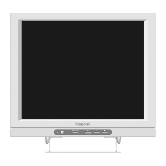
3. Name and Function for Operation Front Side Power LED Power Switch Input signal select key (For VIDEO, S-VIDEO, Component, PC input, DVI input) OSD Menu/Set Key (Colour Pre-set) OSD – (minus) Key (Brightness) OSD+ (plus) Key (Contrast) Rear Side (Standerd) VIDEO input S-VIDEO Input G/Y Input (Component) -
Page 12: Input Signal Connection
4. Input Signal Connection 4-1. NTSC/PAL Analog Video : Connect to the Video input. 4-2. NTSC/PAL Analog S-Video : Connect to the S-Video input. 4-3. RGB or Y.Pb.Pr. Analog Signals (BNC Connector) For G/Y signal : Connect to a component G/Y input. For B/Pb.signal: Connect to a component B/Pb.input. -
Page 13: Operation
5. Operation 5-1. Input Selection and Controls There are 6 keys on the front panel. Those are, (from left to right), Power, Input select key and a Menu/Set key, Plus(+) key and Minus (-) key and a front power switch and power indication LED on far right. POWER : POWER ON/OFF INPUT SELECT :... -
Page 14: Menu Setting And Key Operation
5-3. Menu setting and Key operation The Setup Menu is showing presently input parameters and also setting func- tion. It does not show when parameters are not input, or select to input. 5-3-1. Input signal Selection Use SELECT to select input signals. INPUT SELECT: The signals VBS, Y/C, COMPONENT, PC and DVI are se- lected in this order. -
Page 15: Exit Screen
To adjust an item, select the item in question with the "-" or "+" key (the se- lected item gets highlighted) and press the MENU/SET key. Then the numeri- cal setting of the item in question also gets highlighted and ready to readjust. Using the "-"... -
Page 16: Mode Screen
5-5. MODE Screen This menu is used to preset colors, select the component signal, lock the front keys, switch the aspect ratio, readjust the VIDEO/S-VIDEO setup level, and make the power-save setting. Screen Display • Color Preset: The setting comes in six levels from 000 to 005. The 000 setting is a default that cannot be modified. - Page 17 • Video/S-Video Setup : This is to select a video setup level for composite video, or For Y/C signal input. 0 means the offset level is 0%. Mid means the offset level is 3%. Hi means the offset level is 7.5 %. •...
-
Page 18: Display Control Setup Screen
5-6. Display Control Setup Screen This is to make settings for the display positions or sizes of horizontal and vertical conditions, sampling clock frequency or phase position. Screen Display • H.Position: This is to adjust a horizontal position. (+) key to shift to right side. (-) key to shift to left side. -
Page 19: Image Setting Screen
• Phase : This is to adjust a sampling point of an input signal and may be necessary to make it clear when edges are not clear when you feed signals with characters or letters, or need to display fine charts or drawings. - Page 20 • Chroma: This is to control the density of colour. (+) makes it stronger and(-) makes it paler. • Blue only: This turns the display to Blue colour only. This facilitates adjustments for contrast, brightness, chroma, hue. But this works only with an NTSC composite video input. •...
-
Page 21: Color Control Screen
5-8. Color Control Screen This screen is used to adjust colors. The color temperatures 6500º and 9300º are fixed. Make the OFFSET level for the dark zone of each color (R/G/B) and the GAIN level for the highlights. Each of the data is presettable. Screen display •... - Page 22 • RGB. Offset: The dark zones of all R, G and B are adjusted. The black level of R/G/B gets lower toward the + side and higher toward the - side. • R. Gain: The highlight of R (red) is adjusted. The white level of R gets higher toward the + side and lower toward the - side.
-
Page 23: Reset Selection Screen
5-9. RESET Selection Screen All the settings are returned to their factory ones. Screen display Note: No setup entry can be made without signal being fed. (Input signal switch- ing effective) 5-10. HOT Keys The HOT keys are used to directly control color presetting, brightness and con- trast with the MENU/SET, - and + keys. -
Page 24: Input Signal List
6. Input Signal List 6-1. Control of Input Signals Items for common settings... -
Page 25: Video Signals
6-2. VIDEO Signals 6-3. HD-15 PC signals 6-4. DVI-D PC signals... -
Page 26: Scanning Switch
6-5. Scanning switch... -
Page 27: Simple Trouble Shooting
7. Simple Trouble Shooting If you have trouble or a malfunction with this LCD monitor, please consult with an Authorized person for service. However, the following suggestions may be useful in solving simple problems. No Power: • Please check the other power switch on a rear and also the power switch on a front panel. - Page 28 Colour on the screen is pale : • Is the chroma level set correctly (around 128)? Please Note 128 is the correct level for Composite video input and Y/C input. What about the brightness level, is it too high ? What about the Gamma setting? It should be around 2.2.
- Page 29 Vertical stripes are visible : • Check and adjust the clock signal or the phase with the Display Control Setup Screen. Too much Noise : • Check and adjust the clock signal or the phase with the Display control Setup Screen.
-
Page 30: Specifications
8. Specifications... -
Page 31: External Appearances
9. External Appearances 50.3... - Page 32 2631 Manhattan Beach Blvd., Redondo Beach, C.A. 90278 Phone: (310) 297-1900, Fax: (310) 536-9550 Ikegami Electronics (Europe) GmbH Ikegami Strasse 1, 41460 Neuss, 1, F.R. Germany Phone: 02131-123-0, Fax: 02131-102820 Ikegami Electronics ,U.K. Branch Unit E1, Cologne Court, Brooklands Close, Windmill Road Sunbury-on-Thames Middlesex TW16 7EB, U.K.
Need help?
Do you have a question about the MLM-1581CH and is the answer not in the manual?
Questions and answers