Table of Contents
Advertisement
Jiva TP/LT- 5815 Pro / - 5915 Pro
/ - 8000 / - 8200 Touch Terminal
w/ Slim or Universal Base
User's Manual
Rev.: Original
FCC Notes:
This equipment generates, uses, and can radiate radio frequency energy and, if not
installed and used in accordance with the instructions manual, may cause interference
to radio communications. It has been tested and found to comply with limits for a Class
A digital device pursuant to subpart J of Part 15 of FCC Rules, which are designed to
provide reasonable protection against interference when operated in a commercial
environment. Operation of this equipment in a residential area is likely to cause
interference in which case the user at his own expense will be required to take whatever
measures to correct the interference.
Warranty Limits:
Warranty terminates automatically when any person other than the authorized
technicians opens the machine. The user should consult his/her dealer for the problem
happened. Warranty voids if the user does not follow the instructions in application of
this merchandise. The manufacturer is by no means responsible for any damage or
hazard caused by improper application.
About This Manual:
Posiflex has made every effort for the accuracy of the content in this manual. However,
Posiflex will assume no liability for any technical inaccuracies or editorial or other
errors or omissions contained herein, nor for direct, indirect, incidental, consequential
or otherwise damages, including without limitation loss of data or profits, resulting
from the furnishing, performance, or use of this material.
This information is provided "as is" and Posiflex Inc. expressly disclaims any
warranties, expressed, implied or statutory, including without limitation implied
warranties of merchantability or fitness for particular purpose, good title and against
infringement.
The information in this manual contains only essential hardware concerns for general
user and is subject to change without notice. Posiflex reserves the right to alter product
designs, layouts or drivers without notification. The system integrator shall provide
applicative notices and arrangement for special options utilizing this product. The user
may find the most up to date information of the hardware from web sites:
http://www.posiflex.com or http://www.posiflex.com.tw or http://www.posiflexusa.com
All data should be backed-up prior to the installation of any drive unit or storage
peripheral. Posiflex will not be responsible for any loss of data resulting from the use,
disuse or misuse of this or any other Posiflex product.
All rights are strictly reserved. No part of this documentation may be reproduced,
stored in a retrieval system, or transmitted in any form or by any means, electronic,
mechanical, photocopying, or otherwise, without prior express written consent from
Posiflex Inc. the publisher of this documentation.
© Copyright Posiflex Inc. 2006
All brand and product names and trademarks are the property of their respective holders.
Part 1
P/N: 16320900010
Advertisement
Table of Contents

Subscribe to Our Youtube Channel
Related Manuals for POSIFLEX Jiva TP-8000


Summary of Contents for POSIFLEX Jiva TP-8000
- Page 1 Jiva TP/LT- 5815 Pro / - 5915 Pro / - 8000 / - 8200 Touch Terminal w/ Slim or Universal Base User’s Manual Rev.: Original FCC Notes: This equipment generates, uses, and can radiate radio frequency energy and, if not installed and used in accordance with the instructions manual, may cause interference to radio communications.
- Page 2 ALERT TO OUR HONORABLE CUSTOMERS: l Please always read thoroughly all the instructions and documents delivered with the product before you do anything about it. Don’t take any premature action before you have a full understanding of the consequences. l This product contains inside a Lithium battery and maybe also a sealed type Lead acid battery if the UPS battery option is ordered.
-
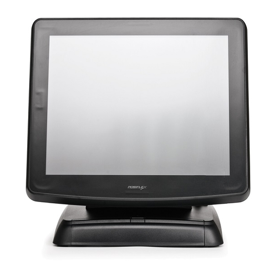
Page 3: Product Pictures
INTRODUCTION PRODUCT PICTURES Front Views TP-5815 Pro / TP-8000 TP-5915 Pro / TP-8200 TP-5815 Pro / TP-8000 TP-5915 Pro / TP-8200 Side Views TP-5915 Pro / TP-8200 TP-5815 Pro / TP-8000 TP-5815 Pro / TP-8000 TP-5915 Pro / TP-8200 Part 3... -
Page 4: Parts Identification
Rear Views TP-5815 Pro / TP-8000 TP-5915 Pro / TP-8200 Bottom Views TP-5815 Pro / TP-8000 TP-5915 Pro / TP-8200 PARTS IDENTIFICATION 1. Main unit 2. Touch panel / LCD panel 3. Optional side mount kit 4. Power status indicator 5. -
Page 5: Product Features
PRODUCT FEATURES Standard Features: CPU: C7 - 1.0 GHz for TP/LT-5815 Pro / -5915 Pro. Celeron 2.0 GHz for TP/LT-8000 / -8200 An advanced slim or universal base design. The slim base (TP/LT-5815 Pro / -8000) supports 2 LCD display or pole mount customer display in desktop mount application and easy wall mount conversion, storage room for HDD and optional UPS battery for both desktop and wall mount applications. - Page 6 DDR DRAM in two modules for TP/LT-8000 / -8200 Integrated structure for side mount upgrade kits (KP-100, SD-100, SD- 200 or BC-100U) and optional top mount customer display PD-302 The MSR in side mount kit is with software programmable parameters for Win 2000 or Win XP pro Built-in UPS function to support the system from intermittent power failure (battery itself is an option)
-
Page 7: Opening Cable Cover
INSTALLATION GUIDES CAUTION: Before any installation or cable connection to the set, please always make certain that the system is turned off and the external power source to the set is removed to prevent electric hazard! Never touch any metal pin in the connectors or circuits to avoid high voltage hazard or electrostatic discharge damage unless the operator is well grounded. -
Page 8: Separating Main Unit
SEPARATING MAIN UNIT In order to settle the touch terminal properly in a point of service system, all the cable connections have to be routed through its base, either slim or universal. Therefore, please observe the procedures from A to C below to separate the main unit from both slim and universal base stand assembly after all cables in cable cover disconnected. -
Page 9: Cable Passage
example on power adaptor portion) will look like the right picture. Both with numbered items listed as below. However, there could be some variation to the contents inside depending on what option items actually installed. 1. Cable Exit For External Connections 2. -
Page 10: Wall Mounting
bracket with its tongue matching under a bridge in the wall of base box from the right as arrowed in above left picture then apply the fixing screw. Please pay particular attention to the environment requirements for UPS battery in next chapter “USING THE TOUCH POS”. -
Page 11: Base Mount Upgrade Kit
all cables coming out of the backpack into the cable cover area of main unit. The area required for wall mount application is determined by the main unit dimensions and is 375 mm in width and 315 mm in height. BASE MOUNT UPGRADE KIT On rear edge of the stand assembly for desktop mount application, there is a rear connect... -
Page 12: Routing The Cables
15” 2 LCD Panel A bracket kit including a steel bracket and 2 types of screws as in the left picture will be provided with the 15” 2 LCD panel. Use 3 smaller screws to fix the bracket to outside of the bottom plate from inside as circled in the right picture that is the bottom view of the base stand. -
Page 13: Desktop Mounting
WIRELESS PRINTER To access the Posiflex wireless thermal printer PP7700 in Windows environment except Win CE, a wireless Dongle DG2000 for this printer must be separately purchased and installed to one of the serial COM ports in Jiva system. Please enable the + 5 V DC power support for this COM port. -
Page 14: Connecting Cables
CONNECTING CABLES To re-assemble the main unit with stand assembly for operation, please connect all required cables to the appropriate connectors. Please make sure that each connector is connected to the correct port with the correct orientation. Damages due to incorrect connection or orientation are not covered by product warranty! Some connectors like the LAN connector have to be gently inserted until a click is heard. -
Page 15: Operating System Installation
OPERATING SYSTEM INSTALLATION This product is a highly professionalized equipment. The installation of an OS into a machine without any preloaded OS could constitute major difficulty for average user or obstacle by possibly unintentional negligence even for PC veterans to accomplish such a task. Therefore, OS installation into a system without preloaded OS is highly discouraged. -
Page 16: Application Environment
USING THE TOUCH TERMINAL APPLICATION ENVIRONMENT It is very important to check the following operational guidelines: Ventilation This terminal must NOT be used in an environment with restricted ventilation. There must be at least 25 mm air clearance around any ventilation holes with a free flow of air around the unit at ALL times for the installation. -
Page 17: Power On/Off
Power Supply The operating voltage range of the power adaptor should cover the local power supply for proper operation. The power cable, the power outlet and any power fusing arrangements must conform to local safety regulations. Please never do any connection / disconnection when system is still powered on. -
Page 18: Display Issues
make sure that the software application has the ability to power off the machine. In preloaded Windows, “Posiflex Power Switch Manager” in “Posiflex Tools” in the Program Files helps managing these functions. Software Support Features The Jiva series provides a software power off for application program maneuvers as mentioned above. -
Page 19: Customer Display
use Posiflex VGA + power cable and set an internal jumper in the main unit to supply the required power through the VGA connector for LM-6212. Do not connect other monitor to this port before the power in this port is disabled. CUSTOMER DISPLAY Please follow the instructions on the manual that comes along with the customer display PD-2501 or PD-2602 when it is installed. -
Page 20: Touch Panel
repeats, please consult your dealer for possibly fan replacement on worn out. TOUCH PANEL All paragraphs below are applicable for models with touch panel only. The user of those models without touch panel can ignore them and consider this user’ s manual ends here. Mouse Emulation The touch panel in Jiva system uses USB interface as standard.
Need help?
Do you have a question about the Jiva TP-8000 and is the answer not in the manual?
Questions and answers