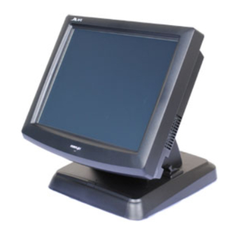
POSIFLEX Jiva – 8300 User Manual

POSIFLEX Jiva – 8300 User Manual

Touch terminal

Advertisement

Jiva/TP/LT – 8300/E
Touch Terminal
User's Manual
FCC Notes:
This equipment generates, uses, and can radiate radio frequency energy and, if not installed and
used in accordance with the instructions manual, may cause interference to radio
communications. It has been tested and found to comply with limits for a Class A digital device
pursuant to subpart J of Part 15 of FCC Rules, which are designed to provide reasonable
protection against interference when operated in a commercial environment. Operation of this
equipment in a residential area is likely to cause interference in which case the user at his own
expense will be required to take whatever measures to correct the interference.
Warranty Limits:
Warranty terminates automatically when any person other than the authorized technicians opens
the machine. The user should consult his/her dealer for the problem happened. Warranty voids if
the user does not follow the instructions in application of this merchandise. The manufacturer is
by no means responsible for any damage or hazard caused by improper application.

About This Manual:

Posiflex has made every effort for the accuracy of the content in this manual. However, Posiflex
will assume no liability for any technical inaccuracies or editorial or other errors or omissions
contained herein, nor for direct, indirect, incidental, consequential or otherwise damages,
including without limitation loss of data or profits, resulting from the furnishing, performance, or
use of this material.
This information is provided "as is" and Posiflex Technology, Inc. expressly disclaims any
warranties, expressed, implied or statutory, including without limitation implied warranties of
merchantability or fitness for particular purpose, good title and against infringement.
The information in this manual contains only essential hardware concerns for general user and is
subject to change without notice. Posiflex reserves the right to alter product designs, layouts or
drivers without notification. The system integrator shall provide applicative notices and
arrangement for special options utilizing this product. The user may find the most up to date
information of the hardware from web sites: www.posiflex.com,
/www.posiflexusa.com.
All data should be backed-up prior to the installation of any drive unit or storage peripheral.
Posiflex will not be responsible for any loss of data resulting from the use, disuse or misuse of
this or any other Posiflex product.
All rights are strictly reserved. No part of this documentation may be reproduced, stored in a
retrieval system, or transmitted in any form or by any means, electronic, mechanical,
photocopying, or otherwise, without prior express written consent from Posiflex Technology, Inc.
the publisher of this documentation.
© Copyright Posiflex Technology, Inc. 2010
All brand and product names and trademarks are the property of their
respective holders.
P/N: 16340900030
Rev.: B0
/www.posiflex.com.tw
or
T31454
警 告 使 用 者
警 告 使 用 者
警 告 使 用 者
警 告 使 用 者
這 是 甲 類 的 資 訊 產 品 , 在 居 住 的 環
境 中 使 用 時 , 可 能 會 造 成 射 頻 干
擾 , 在 這 種 情 況 下 , 使 用 者 會 被 要
求 採 取 某 些 適 當 的 對 策 。
Part 1

Advertisement

Table of Contents
loading
Need help?

Need help?

Do you have a question about the Jiva – 8300 and is the answer not in the manual?

Questions and answers

Subscribe to Our Youtube Channel

Summary of Contents for POSIFLEX Jiva – 8300

  • Page 1: About This Manual

    All data should be backed-up prior to the installation of any drive unit or storage peripheral. Posiflex will not be responsible for any loss of data resulting from the use, disuse or misuse of this or any other Posiflex product.
  • Page 2 Harsh Environments. Otherwise, Overheat or Failure might occur accidentally. This Device Is Not Suggest To USE In High Humidity And High Salinity Environments. It Recommend To Choice POSIFLEX Fan- Free Series Terminals When Use in Harsh Environment. ALERT TO OUR CUSTOMERS: Please always read thoroughly all the instructions and documents delivered with the product before you do anything about it.
  • Page 3: Product Pictures

    INTRODUCTION PRODUCT PICTURES Front Views Side Views Gen 5 base Gen 4 base Rear Views Gen 5 base Gen 4 base Bottom Views Part 3...
  • Page 4: Parts Identification

    PARTS IDENTIFICATION Main unit Touch panel / LCD panel Power status indicator Base stand Cable cover Removal hollow in cable cover Lock / release lever for tilt angle adjust Optional rear top mount kit PD-302 Lock / release button for main unit detach 10.
  • Page 5 5. 5 USB ports 6. one LAN port 10/100/1000 MB Ethernet 7. one external VGA port with capability for +12V DC support(enable/disable by software setting) 8. one additional SATA connector 9. one DC 12 V power input connector 10. one UPS connector 11.
  • Page 6: Opening Cable Cover

    Customer pole display of VFD PD-2300/2500/2600 or graphic LCD PD-302 /305/306. Posiflex stand along pole display such as PD-2800/320. External 12” LCD monitor LM-6101, 15” LCD Monitor LM-6501. m) 2 in 1 cash drawer control cable USB interface wireless LAN 802.11 b/g Optional COM 5/6 for additional peripherals.
  • Page 7: Separating Main Unit

    DISCONNECTING ALL CABLES After removal of the cable cover, the connector area will be accessible then. Please notice that the orientations of every existing cable connection first and disconnect all cables before separating the main unit from the adjustable stand assembly. Please note that the click lock spring has to be pressed down prior to pulling out the connector such as the LAN port or the CR port.
  • Page 8: Cable Passage

    example universal base model will look like the right picture. Both with numbered items listed as below. However, there could be some variation to the contents inside depending on what option items actually installed. Inside Gen 4 base Fixing Screws CABLE PASSAGE 1.
  • Page 9: Installing Ups Battery

    INSTALLING UPS BATTERY The optional UPS battery is delivered in the carton if it is ordered. For slim base model, please place the UPS battery in the direction shown in the right picture and use the Velcro strap through the 2 standing slits on base box to fix the battery in position firmly.
  • Page 10: Base Mount Upgrade Kit

    of the backpack into the cable cover area of main unit. The area required for wall mount application is determined by the main unit dimensions and is 375 mm in width and 315 mm in height. BASE MOUNT UPGRADE KIT On rear edge of the stand assembly for desktop mount application, there is a rear connect cover.
  • Page 11: Routing The Cables

    Please note that only those qualified technicians may adjust in the service window with information from Posiflex and the contents in the Service Window service window may change without notice as time develops.
  • Page 12: Desktop Mounting

    DESKTOP MOUNTING Matching Holes Matching Pegs Round Part Slot Part Removal Hollow Match the matching pegs on the back of the main unit against the matching holes on the stand assembly. Firstly, aim to the matching pegs toward the upper round part of the hole and make sure that all pegs are inside the holes. Next, slide the main unit down to move the pegs into the lower slot part of the holes till it clicks.
  • Page 13: Operating System Recovery

    OPERATING SYSTEM RECOVERY For Jiva systems preloaded with Windows XP Pro, WEPOS or POSReady on HDD, Posiflex provides recovery CD or DVD delivered with the touch terminal for the preloaded operating system. The System Integrator shall take care of software restoration after OS recovered. A Posiflex supplied USB interface CD/DVDROM COMBO drive will be required for such action.
  • Page 14: Application Environment

    USING THE TOUCH TERMINAL APPLICATION ENVIRONMENT It is very important to check the following operational guidelines: Ventilation This terminal must NOT be used in an environment with restricted ventilation. There must be at least 25 mm air clearance around any ventilation holes with a free flow of air around the unit at ALL times for the installation.
  • Page 15: Power On/Off

    WARNING: If there are any signs of over charging or leakage of electrolyte please contact your dealer immediately Power Supply The operating voltage range of the power adaptor should cover the local power supply for proper operation. The power cable, the power outlet and any power fusing arrangements must conform to local safety regulations.
  • Page 16 In preloaded Windows, “Posiflex Power Switch Manager” in “Posiflex Tools” in the Program Files helps managing these functions. Software Support Features The Jiva series provides a software power off for application program maneuvers as mentioned above.
  • Page 17: Display Issues

    For best viewing result please set your display resolution at 1024 x 768 with high color. VGA Port The VGA port in the Jiva system supports Posiflex stand alone touch or LCD monitors like TM-7112 if there is no base mount 2 LCD display. This port supports extended mode dual display function in WinXP.
  • Page 18: Touch Panel

    Posiflex USB Touch Manager A program named “Posiflex USB Touch Manager” and a right-click sticky button tool in the program group “Posiflex USB Touch Tools” is installed in the preloaded Windows system with a USB interface touch panel controller. This program can also be obtained by download from the POSIFLEX web site.
  • Page 19 Windows DOS box should be avoided. Posiflex Touch Terminal Manager A program named “Posiflex Touch Terminal Manager” and a right-click sticky button tool in the program group “Posiflex Tools” is installed in the preloaded Windows system in TP-8300 . This program can also be obtained by download from the POSIFLEX web site.

Table of Contents