Table of Contents
Advertisement
Quick Links
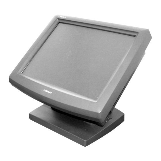
Jiva TP/LT- 5600/5700/5800/8000
Touch Terminal w/ Slim Base
User's Manual
Rev. B1
FCC Notes:
This equipment generates, uses, and can radiate radio frequency
energy and, if not installed and used in accordance with the instructions manual, may
cause interference to radio communications. It has been tested and found to comply
with limits for a Class A digital device pursuant to subpart J of Part 15 of FCC Rules,
which are designed to provide reasonable protection against interference when operated
in a commercial environment. Operation of this equipment in a residential area is likely
to cause interference in which case the user at his own expense will be required to take
whatever measures to correct the interference.
Warranty Limits:
Warranty terminates automatically when any person other than the authorized
technicians opens the machine. The user should consult his/her dealer for the problem
happened. Warranty voids if the user does not follow the instructions in application of
this merchandise. The manufacturer is by no means responsible for any damage or
hazard caused by improper application.
About This Manual:
Posiflex has made every effort for the accuracy of the content in this manual. However,
Posiflex will assume no liability for any technical inaccuracies or editorial or other
errors or omissions contained herein, nor for direct, indirect, incidental, consequential
or otherwise damages, including without limitation loss of data or profits, resulting
from the furnishing, performance, or use of this material.
This information is provided "as is" and Posiflex Inc. expressly disclaims any
warranties, expressed, implied or statutory, including without limitation implied
warranties of merchantability or fitness for particular purpose, good title and against
infringement.
The information in this manual contains only essential hardware concerns for general
user and is subject to change without notice. Posiflex reserves the right to alter product
designs, layouts or drivers without notification. The system integrator shall provide
applicative notices and arrangement for special options utilizing this product. The user
may find the most up to date information of the hardware from web sites:
http://www.posiflex.com or http://www.posiflex.com.tw or http://www.posiflexusa.com
All data should be backed-up prior to the installation of any drive unit or storage
peripheral. Posiflex will not be responsible for any loss of data resulting from the use,
disuse or misuse of this or any other Posiflex product.
All rights are strictly reserved. No part of this documentation may be reproduced,
stored in a retrieval system, or transmitted in any form or by any means, electronic,
mechanical, photocopying, or otherwise, without prior express written consent from
Posiflex Inc. the publisher of this documentation.
© Copyright Posiflex Inc. 2006
All brand and product names and trademarks are the property of their respective holders.
Part 1
P/N: 16280901030
Advertisement
Table of Contents

Related Manuals for POSIFLEX TP/LT- 5600


Summary of Contents for POSIFLEX TP/LT- 5600
- Page 1 Jiva TP/LT- 5600/5700/5800/8000 Touch Terminal w/ Slim Base User’s Manual Rev. B1 FCC Notes: This equipment generates, uses, and can radiate radio frequency energy and, if not installed and used in accordance with the instructions manual, may cause interference to radio communications. It has been tested and found to comply...
- Page 2 ALERT TO OUR HONORABLE CUSTOMERS: l Please always read thoroughly all the instructions and documents delivered with the product before you do anything about it. Don’t take any premature action before you have a full understanding of the consequences. l This product contains inside a Lithium battery and maybe also a sealed type Lead acid battery if the UPS battery option is ordered.
- Page 3 Standard Features: CPU: Eden 667 MHz or up for TP/LT-5600;C3 800 MHz for TP/LT- 5700; C3 1.0 GHz for TP/LT-5800; Celeron 2.0 GHz for TP/LT-8000 Jiva TP/LT-5800/8000 has both system fan and CPU fan with a fan control software in preloaded OS. An advanced slim base design supporting 2 mount customer display in desktop mount application and easy wall mount conversion, storage room for HDD for TP/LT-5800/8000 series...
- Page 4 Touch control functions: left/right button, double click, drag & draw (for Jiva TP only) Dual display support (per OS capability) VGA memory size shared from system memory (16 – 64 MB for TP/LT-5600/5700/5800, 16 – 128 MB for TP/LT-8000) Support high performance DDR DRAM with maximum memory size 1GB for TP/LT-5600/5700/5800, 2GB for TP/LT-8000 in two modules Integrated structure for optional security devices (KP-100, SD-100, SD-...
-
Page 5: Opening Cable Cover
INSTALLATION GUIDES CAUTION: Before any installation or cable connection to the set, please always make certain that the system is turned off and the external power source to the set is removed to prevent electric hazard! Never touch any metal pin in the connectors or circuits to avoid high voltage hazard or electrostatic discharge damage unless the operator is well grounded. -
Page 6: Separating Main Unit
disconnection operation are not covered by product warranty! SEPARATING MAIN UNIT In order to settle the touch terminal properly in a point of sale system, all the cable connections have to be routed through its base, the stand assembly. Therefore, please observe the procedures from A to C below to separate the main unit from the stand assembly after all cables in cable cover disconnected. -
Page 7: Cable Routing
CABLE ROUTING Please route all cables through the cable passage to main unit in desktop mount application. Hold them together with the cable tie. Pass all cables (but those for HDD and UPS battery) through the cable exit to external connections. -
Page 8: Base Mount Upgrade Kit
in squares in lower left picture and allow the main unit to slide down the winding grooves in the wall mount backpack - originally the base box. The stand assembly is not engaged in wall mount operation. Connect all cables coming out of the backpack into the cable cover area of main unit. -
Page 9: Routing The Cables
will look like the right picture. Route the VGA through the cable exit of the base stand to the main unit. Connect the attached power adaptor for its power source. ROUTING THE CABLES Place all the cables required for connections to the main unit except those for the integrated attachment through the front part inside the stand assembly. - Page 10 After the battery is nearly exhausted, the user must change a new battery otherwise the system RTC and system configuration setup will be lost. SIDE & REAR TOP MOUNT UPGRADE KIT Please follow the instructions in the manuals delivered with the side mount upgrade kit: KP100, SD100, SD200 or BC100 and the rear top mount upgrade kit PD302 to fit them in Jiva system construction.
-
Page 11: Desktop Mounting
http://www.posiflex.com.tw DESKTOP MOUNTING Matching Pegs Match the matching pegs on the back of the main unit against the matching holes on the stand assembly. First aim the matching pegs toward the upper round part of the hole and make sure that all pegs are inside the holes. Then slide the main unit down to move the pegs into the lower slot part of the holes till it clicks. -
Page 12: Operating System Recovery
plastic latchkey that is used when removing the cable cover, but be sure to turn it in the clockwise direction to lock the cover in place. Re-adjust the tilt angle of the screen for best viewing. Connect the cables to appropriate external devices through the cable exit at the bottom of stand assembly. -
Page 13: Operating System Installation
subfolder “\drivers” in OS recovered HDD and the latest versions of these required drivers will be available on our web: http://www.posiflex.com.tw. Now please follow instructions from your system integrator for software recovery. OPERATING SYSTEM INSTALLATION This product is a highly professionalized equipment. The installation of an OS into a machine without any preloaded OS could constitute major difficulty for average user who either has barely limited technical knowledge of this professionalized equipment or is insufficiently equipped with necessary... -
Page 14: Using The Touch Pos
USING THE TOUCH POS APPLICATION ENVIRONMENT It is very important that you check the following operational guidelines: Ventilation This terminal must NOT be operated in an environment with restricted ventilation. The installation should be such that there is at least 25mm air clearance around any top or side ventilation holes. -
Page 15: Power On/Off
connected there but found inoperable by such messages. Emergency treatment: The battery is constructed maintenance free and leakproof. It is well protected in Jiva system as long as the ambient temperature remains below 30 C and the ventilation of the Jiva system remains free. However, should any accident happen and the sulfuric acid from the battery spills on skin or clothing, wash immediately with water. - Page 16 LED Status System Status External Power UPS Battery Powering Up Green Blue Blue/flash Green/rapid flash Hardware Power Switch The power switch located at left side of the main unit is a slide type switch. This switch controls the power on/off of the system. This switch turns the system on when slid downward, only when external power is present.
-
Page 17: Display Issues
Automatic Power On Control The system may also turn on according to some preset conditions such as Modem Ring Up and Alarm Clock Wake Up or LAN Wake Up. To utilize Modem Ring Up or Alarm Clock Wake Up function, the user should enter the CMOS setup by pressing “Del”... -
Page 18: Fan Control
SERIAL PORTS – COM1/2/3/4 In Jiva system, there are 4 serial ports available. All the serial ports can supply a +5 V DC through pin 9 after proper jumper setting change. All 4 ports are standard RS232 serial ports as status at delivery. When a serial Modem is to be used in Jiva system, it is most recommended to use COM2 or COM3 or COM4 port for this purpose. - Page 19 TOUCH PANEL (for TP models only) All paragraphs below are applicable in TP-5615, TP-5715, TP-5815 or TP-8015 only. The user of LT-5615, LT-5715, LT-5815 or LT-8015 can ignore them and consider this user’s manual ends here. Mouse Emulation The touch panel in Jiva TP system uses PS2, RS232 or USB interface. When its driver is properly installed, this touch panel works exactly like a standard mouse.
- Page 20 sticky button tool in the program group “Posiflex USB Touch Tools” is installed in the preloaded Windows system with a USB interface touch panel controller. This program can also be obtained by download from the POSIFLEX web site. T31454 警告使用者 這是甲類的資訊產品,在居住的環...
Need help?
Do you have a question about the TP/LT- 5600 and is the answer not in the manual?
Questions and answers