Table of Contents
Advertisement
Quick Links
© 2011, Moog Videolarm, Inc. All Rights Reserved
Q R H W
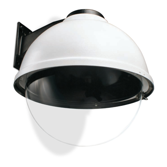
QView™ Series QRH Rugged Dome
Installation and Operation Instructions for the following models:
QRHWT2-70NA
Sever and volatile environmental housing, tinted dome with two (2) Day/Night
cameras, 3-9mm auto-iris lens
QRHWT4-70NA
Sever and volatile environmental housing, tinted dome with four (4) Day/Night
cameras, 3-9mm auto-iris lens
Before attempting to connect or operate this product, please read these instructions completely.
To be used with the 81-IN5409 Instruction Manual.
www.videolarm.com
81-IN5338
01-27-2012
Advertisement
Table of Contents

Related Manuals for Moog Videolarm QRHW SERIES


Summary of Contents for Moog Videolarm QRHW SERIES
- Page 1 © 2011, Moog Videolarm, Inc. All Rights Reserved Q R H W QView™ Series QRH Rugged Dome www.videolarm.com Installation and Operation Instructions for the following models: QRHWT2-70NA Sever and volatile environmental housing, tinted dome with two (2) Day/Night cameras, 3-9mm auto-iris lens QRHWT4-70NA Sever and volatile environmental housing, tinted dome with four (4) Day/Night cameras, 3-9mm auto-iris lens 81-IN5338 Before attempting to connect or operate this product, please read these instructions completely. 01-27-2012 To be used with the 81-IN5409 Instruction Manual.
-
Page 2: Important Safeguards
IMPORTANT SAFEGUARDS SAFETY PRECAUTIONS Read these instructions. Keep these instructions. CAUTION Heed all warnings RISK OF ELECTRIC SHOCK DO NOT OPEN Follow all instructions. Do not use this apparatus near water. CAUTION: TO REDUCE THE RISK OF Clean only with damp cloth. ELECTRIC SHOCK, DO NOT REMOVE COVER ( OR BACK). - Page 3 If Purchaser believes that the Product is defective in material or workmanship, then written notice with an explanation of the claim shall be given promptly by Purchaser to Moog Videolarm. All claims for warranty service must be made within the warranty period.
- Page 4 CABLE AND POWER GUIDELINES This chart shows the proper current needed for power supplies for Q-View™ cameras. Use Class 2 Power only. Input voltage must be 24Vac/Vdc. CAMERAS VOLTAGE CURRENT POWER 1 24 VAC/VDC 102mA 2.5W 2 24 VAC/VDC 210mA 5W 3 24 VAC/VDC 331mA 7.9W 4 24 VAC/VDC 487mA 10.9W Use the formula below to select the correct power supply for cameras connected in parallel (positive to positive, negative to negative): Total current for a 24 VAC system: TOTAL CURRENT = (202mA x total number of cameras) Note: 202mA is camera plus power supply Figure 1 ELECTRICAL SPECIFICATIONS (OUTDOOR ONLY): Power 24VAC, Class 2 Only Loosen screws only, do not remove 26 watts at 24 VAC Heater and Blower Heater: 25 watts Blower: 1 watt Remove dome by twisting Input Connectors (outdoor units): counter-clockwise until it stops, Camera Power, BNC then pull down...
- Page 5 2. Undo the safety cable and twist the housing onto the housing coupling. Secure all (3) setscrews provided on the housing coupling (Figure 4, next column). 3. Clean the outside of the dome. Access panel Figure 2 Twist and 4. Attach the wires from the wall to the connector provided, using the wiring color Secure code chart as a guide. 5. Once all wiring connections are made, place the wires inside the wall mount bracket and close the access door. Secure with the screw removed earlier. 6. Clean the outside of the dome. FOR OPTIONAL PENDANT MOUNT 1. This unit includes a 1 1/2" NPT housing for a standard 1 1/2" NPT pipe. The RH7C can be used with other brackets designed with 1 1/2" male pipe threads, such as the Moog Videolarm WM20G and WM20 wall mount brackets. 2. Attach the housing coupling (Figure 3). NOTE: Pipe threads should be clean and rust free. Use a sealer (such as Teflon™ tape or silicone sealer) on the threads. Figure 4 Wiring Color Code for Power POWER Add thread sealing Camera Power (24 VAC) tape Camera Power (24 VAC) Orange Accessory Power (24 VAC) Yellow Accessory Power (24 VAC) Green...
-
Page 6: Cable And Power Guidelines
13Ω 26Ω 52Ω 78Ω 108Ω 163Ω * Copper clad steel core, 95% braided shield NOTE: The above table is based on a "worst-case" power supply. Using a regulated or switching power supply can increase your cable distance. Moog Videolarm recommends using our PS24 power supply, or a CSA/UL listed Class 2 power supply. The QRH is setup with (2) individual power inputs. 24V AC Wiring Distances 1. Accessory Power (yellow and green wire) The following are the recommended maximum distances for 24 VAC 2. Camera Power (red and orange) with a 10% voltage drop (10% is generally the maximum allowable voltage drop for AC powered devices). - Page 7 CAMERA ADJUSTMENT CAMERA SETTINGS NOTE: To determine which camera is used in your unit, locate the serial number on the 1. Access the cameras by removing the dome. Loosen the locking screws on the lip of inside of the housing. Match the two letter prefix with the corresponding instructions the dome. DO NOT TAKE THESE SCREWS OUT. Once the screws are loosened, turn the included here for adjustments. dome counter clockwise until it stops, then pull the dome off. CAMERA FOCUSING (FOR EACH CAMERA) HIGH-RES BLACK & WHITE Fixed Lens: Loosen the set screw in the lens mount. Manually rotate the lens until a clear picture is achieved. Once the focus is set, retighten the set screw (Figure 5). FIXED AND FIXED VARI-FOCAL LENSES. There are no user adjustable settings on these units (Figure 7). Set screw Fixed lens BW Fixed and Vari-Focal Figure 5 Figure 7 Auto Iris Lens: NOTE: THE AUTO IRIS LENS IS SET AT THE FACTORY. • IF YOU EXPERIENCE VIDEO TOO LIGHT OR DARK AUTO IRIS LENSES. The dip switches are factory set with AES off and backlight AUTO IRIS ADJUSTMENT MAY BE NEEDED. compensation on (Figure 8). The auto iris is also set at the factory, but an adjustment screw is included for use if needed. See page 10 for instructions on adjusting Auto Iris. SEE THE TROUBLESHOOTING SECTION FOR ADJUSTMENT INFORMATION.
-
Page 8: Completion Of Installation
COMPLETION OF INSTALLATION HIGH-RES COLOR, FIXED LENS FIXED AND FIXED VARI-FOCAL LENSES. There are no user adjustable settings on these 1. When the desired focus is achieved for each camera, adjust the segmented bracket units (Figure 14) arms to the desired viewing angle. Once you've finished, put the dome back in place AUTO IRIS LENSES: The auto iris can be adjusted if needed. See the Troubleshooting and check to be sure none of the cameras touch the dome. If one or more do, readjust section for instructions. the arm(s) until they are clear of the dome. 2. Reattach the dome by putting it in place, turning clockwise until it locks, and then tightening the locking screws. Auto Iris NVT INSTRUCTIONS adjustment screw UNSHIELDED TWISTED PAIR Figure 14 VIDEO WIRING HIGH-RES COLOR & DAY/NIGHT w/AUTO-IRIS NOTE: The customer must purchase the Video Transceiver from NVT. Part numbers are: NOTE: This hi-res color camera uses a 1/4" chip and a 3-6mm auto iris lens. It is • NV-212A (500 ft.) comparable to a 1/3" chip using a 4-9mm auto iris lens. * NV-213A or NV-213A-M (1000 ft.) • NV-652R, NV-862R, or NV-1662R (3000 ft.) The operational settings are defined by four dip switches located on the side of the PC... -
Page 9: Wiring Notes
Wiring Notes Wire — What to DO 1. DO use point-to-point Unshielded Twisted Pair wire, gauge 24 or thicker, stranded or solid, Category 2, 3, 4, or 5. 2. The video signal may co-exist in the same wire bundle as other video, telephone, data, control signals, or low-voltage power. It is also OK to run NVT video signals in or near electromagnetic fields (in accordance with National Electrical Code, local, or other local safety requirements). 3. DO measure the wire distance. Use only transceivers that are designed for that distance. 4. DO make sure the pair of wires carrying the video signal is sent as a twisted pair (e.g. the blue-white/white-blue wires twisted together as a pair), not a “split-pair” (e.g. blue-white conductor, part of one pair/orange-white conductor, part of another pair). Wire — What NOT to DO 1. DO NOT USE SHIELDED TWISTED PAIR WIRE. It will severely degrade the distance performance. Short runs may be used with some signal degradation (for example elevator traveler cables). Multi-pair wire with an overall shield is OK. 2. DO NOT USE UN-TWISTED WIRE. It will reduce the NVT product’s inherent interference immunity. 3. DO NOT allow your installation to have “bridge-taps”, loading coils, talk-battery, or MOV type protectors. Bridge-taps are where a twisted pair is connected to two twisted pairs (such as an extension phone at home). Bridge-taps cause reflections... - Page 10 If the voltage is greater than 1/2 volt, use an amplified receiver, such as the NV-652R, NVT TROUBLESHOOTING NV-862R, or NV-1662R. If you are experiencing problems, attempt to simplify your setup. Test each cable Alternately, remove the ground at one end (usually at the camera end). Be sure that segment separately. For example, test the camera and monitor together without the floating the camera conforms to local/regional and National Electrical Codes. other equipment. Then add in the NVT transceivers, back-to-back. Test each segment of a long cable-run independently. Attempt to isolate the problem. 4. Check for crosstalk from a second video path. Disconnect all other video sources. Below are problems that may be encountered. If the suggestions below are not helpful, If the problem goes away, check for a split-pair or un-twisted wire. or the recommendations are not effective, please call NVT’s customer support. NVT customer support can be reached 8:00 AM to 5:30 PM PST at (800) 959-9870 or at FAINT STRIPES GLIDING UP OR DOWN THE SCREEN (+1) (650) 562-0600.
-
Page 11: Troubleshooting
Power Figure B Power B COLOR & DAY/NIGHT AUTO-IRIS Auto Iris Video Signal Adjustment Monitor Screw (Ground Return) Video Shield Figure D Figure A Ground Loop IMPORTANT NOTE ON AUTO IRIS ADJUSTMENT: IMPORTANT NOTE: If you have removed the ground loop and the horizontal line still WHEN ADJUSTING, USE A SMALL, INSULATED SCREWDRIVER. The auto iris remains on screen call Moog Videolarm technical support for further information. adjustments are very sensitive. Use gentle pressure when turning. To adjust, turn either clock-wise or counter-clockwise no more than one degree at a time. Check the monitor after each turn to determine is the desired brightness and color have been obtained. When the adjustment is satisfactory, place a hand over the lens to block out all light. Quickly remove the hand to be sure the iris reacts. - Page 12 QRHW / QRHP - Exploded Diagram for Replacement Parts...
-
Page 13: Replacement Parts List
QRHW / QRHP - Replacement Parts List Part Number Description RPRH701 Lower Trim Ring (Gray) RPRH702 Lower Trim Ring (White) RC7T Tinted Replacement Capsule RC7C Clear Replacement Capsule RPRH703 Dome Clamping Bracket RPFD072 24 VAC Heater RPFD080 (12 VDC) Blower (Used in 24 V Housings) RPFD050 (Model RH7HB) Connection PCB RPRH706 (Model RH7FHB) Connection PCB (Fixed Models) RPRH707 (Model RH7NHB) Connection PCB (Network Models) RPFD060 Camera Bracket RPFD040 Upper Bracket Assembly RPRH709 Housing Top (Gray) RPRH710 Housing Top (White) WM10 WM10 Wall Mount RPQF01 PC Board and Input Cables Video/Power RPQF02... - Page 14 Mounting Template R .733 2.132 5.500 1.537 2.981 2.000 3.250...
-
Page 15: Product Registration/Warranty
Product Registration/Warranty Thank you for choosing Moog Videolarm. We value your patronage and are solely committed to providing you with the highest quality products available and superior customer service. Should a problem arise, rest assure that Moog Videolarm stands behind its products by offering impressive warranty plans: 3 Years on all Housings, Poles, Power Supplies, and Accessories and 5 Years on camera systems (SView, QView, Warriors), and InfraRed Illuminators. Register Your Products Online Take a few moments and validate your purchase via the Online Product Registration Form at www.videolarm.com/productregistration.jsp Register your recent Moog Videolarm purchases and benefit from the following: • Simple and Trouble-Free RMA process • Added into customer database to receive product updates / news • Eliminate the need to archive original purchase documents: Receipts, Purchase Orders, etc…...
Need help?
Do you have a question about the QRHW SERIES and is the answer not in the manual?
Questions and answers