Table of Contents
Advertisement
Quick Links
© 2011, Moog Videolarm, Inc. All Rights Reserved
Q M R
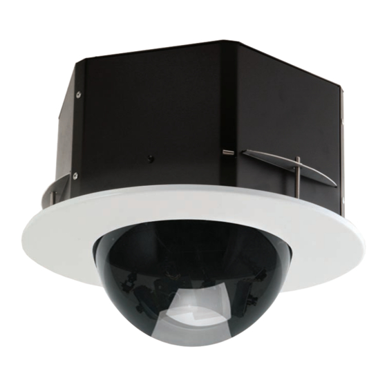
QView™ Series Ceiling Mount Dome
Installation and Operation Instructions for the following models:
QMRT2-70NA
Recessed tinted indoor/outdoor ceiling dome, with two (2) Day/Night
cameras, 3-9mm auto-iris lens
QMRT4-70NA
Recessed tinted indoor/outdoor ceiling dome, with four (4) Day/Night cameras,
3-9mm auto-iris lens
Before attempting to connect or operate this product, please read these instructions completely.
To be used with the 81-IN5409 Instruction Manual.
www.videolarm.com
81-IN5258
01-31-2012
Advertisement
Table of Contents

Subscribe to Our Youtube Channel
Related Manuals for Moog Videolarm QMR SERIES


Summary of Contents for Moog Videolarm QMR SERIES
- Page 1 © 2011, Moog Videolarm, Inc. All Rights Reserved Q M R QView™ Series Ceiling Mount Dome www.videolarm.com Installation and Operation Instructions for the following models: QMRT2-70NA Recessed tinted indoor/outdoor ceiling dome, with two (2) Day/Night cameras, 3-9mm auto-iris lens QMRT4-70NA Recessed tinted indoor/outdoor ceiling dome, with four (4) Day/Night cameras, 3-9mm auto-iris lens 81-IN5258 Before attempting to connect or operate this product, please read these instructions completely. 01-31-2012 To be used with the 81-IN5409 Instruction Manual.
- Page 2 IMPORTANT SAFEGUARDS SAFETY PRECAUTIONS Read these instructions. Keep these instructions. CAUTION Heed all warnings RISK OF ELECTRIC SHOCK DO NOT OPEN Follow all instructions. Do not use this apparatus near water. CAUTION: TO REDUCE THE RISK OF Clean only with damp cloth. ELECTRIC SHOCK, DO NOT REMOVE COVER ( OR BACK).
- Page 3 If Purchaser believes that the Product is defective in material or workmanship, then written notice with an explanation of the claim shall be given promptly by Purchaser to Moog Videolarm. All claims for warranty service must be made within the warranty period.
-
Page 4: Table Of Contents
TABLE OF CONTENTS 4. Remove the trim ring/dome assembly by pulling on the outside of the trim ring. The ring and dome are connected by three flat springs, which press against the side Cable and Power Guidelines..........1, 11 of the housing and lock into (3) cutouts. Electrical Specifications........... 1 5. Run electrical cable and video leads into the housing through the conduit Housing Installation............1 knock-out. Wiring................2 Camera Adjustment............2 6. With the (3) support arms rotated to the inside, slide the housing into the pre-cut Camera Focusing..............2 hole (Figure 1). Camera Settings Black/White..............2 Color................3 Mounting Holes Completion of Installation..........3 NVT Instructions...............3 Support Arm Holes Exploded View..............5 Warranty Information............ -
Page 5: Wiring
WIRING CAMERA SETTINGS 1. Make the proper connections to the incoming power. The RED wire is POSITIVE (+), NOTE: To determine which camera is used in your unit, locate the serial number the BLACK wire is NEGATIVE (-) (For reference purposes. Polarity is not important in on the inside of the housing. Match the two letter prefix with the corresponding this unit). The GREEN wire, labeled Ground, is GROUND for VAC or VDC connections. instructions included here for adjustments. NOTE: Connect green ground wire to earth ground (metal conduit,metal stud, etc.) SERIAL NUMBERS BEGINNING WITH YK 2. Attach the BNC connectors to the video in. FIXED AND FIXED VARI-FOCAL LENSES. There are no user adjustable settings on CAMERA ADJUSTMENTS these units (Figure 7). 1. After completing installation of the housing, use the segmented arms to adjust each BW Fixed and Vari-Focal camera to the desired viewing location (Figure 4). 2. Once camera adjustments are made, place the dome back into position to be sure cameras are not touching the inside of the dome. If any do, adjust until they are clear. Figure 7 AUTO IRIS LENSES. The dip switches are factory set with AES off and backlight Figure 4 compensation on (Figure 8). The auto iris is also set at the factory, but an adjustment screw is included for use if needed. See page 10 for instructions on adjusting Auto Iris. -
Page 6: Color
MC CAMERA DIP SWITCH SETTINGS CHART SERIAL NUMBERS BEGINNING WITH MC The operational settings for the camera are defined by ten dip switches located on the SWITCH SETTING DEFINITION PC Board (Figure 9). Moving the switches to the on position will activate each setting. Flickerless Mode Factory defaults are pictured below (Figure 10 and 11). Setting this switch to "On" and switch 3 (MIRIS) to "Off" will help to reduce the flicker in fluorescent lights. Hi-Res Color, Fixed and Vari-focal fixed lenses Factory BLC (Back Light Helps prevent an object from being Use Only Dip Switches Compensation) washed out when the object is directly in front of a light source. Auto Iris adjustment Connection to MIRIS (Manual/... -
Page 7: Completion Of Installation
COMPLETION OF INSTALLATION SERIAL NUMBERS BEGINNING WITH CB Once all connections and adjustments have been made reattach the trim ring/dome NOTE: This hi-res color camera uses a 1/4" chip and a 3-6mm auto iris lens. It is assembly by pressing in and sliding the three flat springs into the housing (Figure 15). comparable to a 1/3" chip using a 4-9mm auto iris lens. Make sure the springs are aligned with the three spring slots. You will feel all three The operational settings are defined by four dip switches located on the side of the PC springs snap into place when the dome is correctly secured into place. Rotate the Board (Figure 12 and 13). Moving the switches to the UP position will activate specific dome for final proper positioning of the liner and camera. settings. Refer to the chart below. Dip Switches Auto Iris Adjustment Screw Figure 15 Figure 12 NVT INSTRUCTIONS UNSHIELDED TWISTED PAIR VIDEO WIRING NOTE: The customer must purchase the Video Transceiver from NVT. Part numbers are: •... - Page 8 Measure your wire distance 2. Connect the other end of the unshielded twisted pair cable to the NVT receiver. CAUTION: The unshielded twisted pair video signal is polarity dependent. The Note: All NVT quoted distance specifications include any coax in the positive video wire for each camera MUST be connected to the run. It is recommended that the wire distance be measured to ensure positive terminal on the NVT receiver, and negative MUST be that the capability of the NVT product is correct. connected to negative. Wire resistance may be measured with an ohm-meter by shorting 3. When using unshielded twisted pair cable you DO NOT need the BNC connector. All the two conductors together at the far end, and measuring the four BNC connectors are provided inside the housing for testing purposes. Be sure that loop-resistance out and back. Compare your readings with the charts there is no video connection other than the unshielded twisted pair cable. below. Cable Unshielded Twisted-Pair Wire Gauge (AWG) Distance Wiring Notes 250 ft Wire — What to DO 300 ft 400 ft 1. DO use point-to-point Unshielded Twisted Pair wire, gauge 24 or thicker, stranded 500 ft 600 ft...
- Page 9 MR7 - Exploded Diagram and Replacement Parts List...
- Page 10 Part Number Description RPOD01 PC BOARD AND INPUT CABLES VIDEO/POWER RPOD01-NVT PC BOARD AND INPUT CABLES VIDEO/POWER WITh NVT RPQF02 MULTI CAMERA METAL BASE BRACKET RPQF03 CAMERA BRACKET AND hARDWARE RPQF03-20NA CAMERA BRACKET AND hARDWARE - (20 NA MODELS) RPQF04 PLASTIC ARTICULATED BRACKET RPQF20NF3 hI-RES B&W 3.6 FIxED LENS...
-
Page 11: Troubleshooting
SERIAL NUMBER CT CAMERAS Auto Iris Adjustment IMPORTANT NOTE: If you have removed the ground loop and the horizontal line still Screw remains on screen call Videolarm technical support for further information. LINE LOCK Figure E All cameras are all shipped from the factory with the line lock function disabled. If your application requires Line Lock contact Moog Videolarm. IMPORTANT NOTE ON AUTO IRIS ADJUSTMENT: AUTOMATIC BROWN OUT FEATURE WHEN ADJUSTING, USE A SMALL, INSULATED SCREWDRIVER. The auto iris adjustments are very sensitive. Use gentle pressure when turning. To adjust, turn either clock-wise or counter-clockwise no more than one degree at a time. Check The camera includes an automatic brown out feature which is activated whenever the the monitor after each turn to determine is the desired brightness and color have incoming voltage drops below 10 VAC or VDC. - Page 12 If the voltage is greater than 1/2 volt, use an amplified receiver, such as the NV-652R, NVT TROUBLESHOOTING NV-862R, or NV-1662R. If you are experiencing problems, attempt to simplify your setup. Test each cable Alternately, remove the ground at one end (usually at the camera end). Be sure that segment separately. For example, test the camera and monitor together without the floating the camera conforms to local/regional and National Electrical Codes. other equipment. Then add in the NVT transceivers, back-to-back. Test each segment of a long cable-run independently. Attempt to isolate the problem. 4. Check for crosstalk from a second video path. Disconnect all other video sources. If Below are problems that may be encountered. If the suggestions below are not helpful, the problem goes away, check for a split-pair or un-twisted wire. or the recommendations are not effective, please call NVT’s customer support. NVT customer support can be reached 8:00 AM to 5:30 PM PST at (800) 959-9870 or at FAINT STRIPES GLIDING UP OR DOWN THE SCREEN (+1) (650) 562-0600. These are caused by crosstalk from a second video path, or with ground-loops in installations employing passive models at both ends. 1. To identify, disconnect all other video signals temporarily. If the interference goes FAINT OR BLURRY PICTURE; LITTLE OR NO COLOR away, check the wire to make sure the signal is traveling through a twisted pair. Is two-way video being sent more than 1,000 ft (300m) over Category 2 or 3 wire? If so, Possible causes include: the send and receive signals may need to go in separate jacketed cables, or upgrade 1. Shielded twisted-pair cable. Verify that the wire is unshielded twisted-pair cable.
- Page 13 CABLE AND POWER GUIDELINES This chart shows the proper current needed for power supplies for Q-View Series cameras. Use Class 2 Power only. Input voltage must be 24 VAC/VDC. CAMERAS VOLTAGE CURRENT POWER 24 VAC/VDC 102mA 2.5W 24 VAC/VDC 210mA 24 VAC/VDC 331mA 7.9W 24 VAC/VDC 487mA 10.9W Use the formula below to select the correct power supply for cameras connected in parallel (positive to positive, negative to negative): Total current for a 24 VAC system: TOTAL CURRENT = (202mA x total number of cameras) Example: 202mA x 5 total cameras = 1010mA Note: 202mA is camera plus power supply Power Supply Cable Maximum Length (feet/meters) CAMERAS...
- Page 14 Product Registration/Warranty Thank you for choosing Moog Videolarm. We value your patronage and are solely committed to providing you with the highest quality products available and superior customer service. Should a problem arise, rest assure that Moog Videolarm stands behind its products by offering impressive warranty plans: 3 Years on all Housings, Poles, Power Supplies, and Accessories and 5 Years on camera systems (SView, QView, Warriors), and InfraRed Illuminators. Register Your Products Online Take a few moments and validate your purchase via the Online Product Registration Form at www.videolarm.com/productregistration.jsp Register your recent Moog Videolarm purchases and benefit from the following: • Simple and Trouble-Free RMA process • Added into customer database to receive product updates / news • Eliminate the need to archive original purchase documents: Receipts, Purchase Orders, etc…...
Need help?
Do you have a question about the QMR SERIES and is the answer not in the manual?
Questions and answers