Table of Contents
Advertisement
Quick Links
© 2011, Moog Videolarm, Inc. All Rights Reserved
Q F D
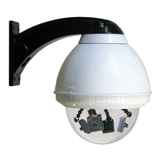
Outdoor Surveillance Housing
Installation and Operation Instructions for the following models:
QFDWT2-70NA Standard 7" outdoor, wall mount, tinted dome, with (2) Day / Night
cameras, 3-9mm auto-iris lens.
QFDWT4-70NA Standard 7" outdoor, wall mount, tinted dome, with (4) Day / Night
cameras, 3-9mm auto-iris lens.
Before attempting to connect or operate this product, please read these instructions completely.
www.videolarm.com
81-IN5247
12-20-2011
Advertisement
Table of Contents

Related Manuals for Moog Videolarm QFD SERIES


Summary of Contents for Moog Videolarm QFD SERIES
- Page 1 © 2011, Moog Videolarm, Inc. All Rights Reserved Q F D Outdoor Surveillance Housing www.videolarm.com Installation and Operation Instructions for the following models: QFDWT2-70NA Standard 7" outdoor, wall mount, tinted dome, with (2) Day / Night cameras, 3-9mm auto-iris lens. QFDWT4-70NA Standard 7" outdoor, wall mount, tinted dome, with (4) Day / Night cameras, 3-9mm auto-iris lens. 81-IN5247 12-20-2011 Before attempting to connect or operate this product, please read these instructions completely.
- Page 2 IMPORTANT SAFEGUARDS SAFETY PRECAUTIONS Read these instructions. Keep these instructions. CAUTION Heed all warnings RISK OF ELECTRIC SHOCK DO NOT OPEN Follow all instructions. Do not use this apparatus near water. CAUTION: TO REDUCE THE RISK OF Clean only with damp cloth. ELECTRIC SHOCK, DO NOT REMOVE COVER ( OR BACK).
- Page 3 If Purchaser believes that the Product is defective in material or workmanship, then written notice with an explanation of the claim shall be given promptly by Purchaser to Moog Videolarm. All claims for warranty service must be made within the warranty period.
-
Page 4: Table Of Contents
Use the formula below to select the correct power supply for cameras connected in parallel (positive to positive, negative to negative): Total current for a 24 VAC system: TOTAL CURRENT = (202mA x total number of cameras) PENDANT MOUNTING THE QFD AND QIFD Note: 202mA is camera plus power supply 1. This unit includes a 1 1/2" NPT housing coupling that can be used with a standard 1 1/2" NPT pipe or with brackets designed with 1 ½" male pipe threads, such as ELECTRICAL SPECIFICATIONS (OUTDOOR ONLY): Moog Videolarm's WM20G. Power 24VAC, Class 2 Only 2. Attach the coupling to the bracket or pendant pipe (Figure 2). NOTE: Pipe threads should be clean and rust free. Use a sealer (such as Teflon™ 26 watts at 24 VAC (accessories) tape or silicone sealer) on the threads for outdoor applications. Heater: 25 watts Blower: .84 watts Input Connectors (outdoor units):... -
Page 5: Wiring
3. Bring all wiring through the NPT pipe or bracket. Vari-Focal Lens: First, adjust the Magnification Lock Screw to the desired magnification (telephoto to wide angle). Tighten the Lock Screw. Next, adjust the Focus Lock Screw until a clear picture is achieved. Tighten the Lock Screw (Figure 6). 4. Mount the housing assembly to the mounting bracket and housing coupling. A safety cable is included with the housing to temporarily hold it while making wiring connections. Loop the safety cable over one of the set screws on the housing coupling (Figure 3). Magnification lock Focus lock screw screw Twist and Secure Fixed iris vari-focal lens Figure 6 Figure 3 Auto Iris Lens: 5. Make the proper connections to the incoming power (See Wiring section below) and NOTE: THE AUTO IRIS LENS IS SET AT THE FACTORY. attach all BNC connectors to the video in. • IF YOU EXPERIENCE VIDEO TOO LIGHT OR DARK 6. Place the finished wiring inside the pendant pipe. Undo the safety cable and twist AUTO IRIS ADJUSTMENT MAY BE NEEDED. - Page 6 MC CAMERA DIP SWITCH SETTINGS CHART SERIAL NUMBERS BEGINNING WITH MC The operational settings for the camera are defined by ten dip switches located on the SWITCH SETTING DEFINITION PC Board (Figure 9). Moving the switches to the on position will activate each setting. Flickerless Mode Setting this switch to "On" and switch Factory defaults are pictured below (Figure 10 and 11). 3 (MIRIS) to "Off" will help to reduce the flicker in fluorescent lights Hi-Res Color, Fixed and Vari-focal fixed lenses BLC (Back Light Helps prevent an object from being Factory washed out when the object is Compensation) Use Only Dip Switches directly in front of a light source. Auto Iris MIRIS (Manual/ When the switch is in the on position adjustment Connection to the auto iris lens controls the amount Electronic Iris screw Power Board of light on the chip. If in the off position the light level is controlled DO NOT electronically.
-
Page 7: Completion Of Installation
COMPLETION OF INSTALLATION SERIAL NUMBERS BEGINNING WITH CB NOTE: This hi-res color camera uses a 1/4" chip and a 3-6mm auto iris lens. It is 1. When the desired focus is achieved for each camera, adjust the segmented bracket comparable to a 1/3" chip using a 4-9mm auto iris lens. arms to the desired viewing angle. Once you've finished, put the dome back in place and check to be sure none of the cameras touch the dome. If one or more do, readjust The operational settings are defined by four dip switches located on the side of the PC the arm(s) until they are clear of the dome. Board (Figure 12 and 13). Moving the switches to the UP position will activate specific settings. Refer to the chart below. 2. Reattach the dome by putting it in place, turning clockwise until it locks, and then tightening the locking screws. Dip Switches NVT INSTRUCTIONS Auto Iris UNSHIELDED TWISTED PAIR Adjustment VIDEO WIRING Screw NOTE: The customer must purchase the Video Transceiver from Figure 12 NVT. Part numbers are: • NV-212A (500 ft.) * NV-213A or NV-213A-M (1000 ft.) • NV-652R, NV-862R, or NV-1662R (3000 ft.) The cameras included in the Q-View™ series have the option of transmitting video signals to NVT receivers via unshielded twisted pair cable. You must purchase the receiver separately. Instructions for connecting the receiver end of the unshielded twisted pair cable will be included with the NVT receiver. Following are instructions Figure 13 for connecting the unshielded twisted pair cables to the RJ45 (Cat. 5) cable running... - Page 8 Wiring Notes Wire — What to DO 1. DO use point-to-point Unshielded Twisted Pair wire, gauge 24 or thicker, stranded or solid, Category 2, 3, 4, or 5. 2. The video signal may co-exist in the same wire bundle as other video, telephone, data, control signals, or low-voltage power. It is also OK to run NVT video signals in or near electromagnetic fields (in accordance with National Electrical Code, local, or other local safety requirements). 3. DO measure the wire distance. Use only transceivers that are designed for that distance. 4. DO make sure the pair of wires carrying the video signal is sent as a twisted pair (e.g. the blue-white/white-blue wires twisted together as a pair), not a “split-pair” (e.g. blue-white conductor, part of one pair/orange-white conductor, part of another pair). Wire — What NOT to DO 1. DO NOT USE SHIELDED TWISTED PAIR WIRE. It will severely degrade the distance performance. Short runs may be used with some signal degradation (for example elevator traveler cables). Multi-pair wire with an overall shield is OK. 2. DO NOT USE UN-TWISTED WIRE. It will reduce the NVT product’s inherent interference immunity. 3. DO NOT allow your installation to have “bridge-taps”, loading coils, talk-battery, or MOV type protectors. Bridge-taps are where a twisted pair is connected to two twisted pairs (such as an extension phone at home). Bridge-taps cause reflections...
-
Page 9: Exploded View
EXPLODED VIEWS OF HOUSING Wall Mount Assembly Item No. Description Part No. 1 Wall Mount Bracket Assembly 40-BRWM12 1 2 FD8 Housing Top 30-VL1697 1 3 Dome Support Ring 30-VL1695 1 4 25W, 24VAC w/Leads 72-HT1752 1 5 FD8 Clear Dome 20-DCFD8 1 n/s FD8 Tinted Dome 20-DTFD8 1 n/s 9.25" O-ring 96-RSORG11 2 6 Plastic Ring Plugs 30-VL1696 6 7 FD8 PCB 76-FPD8PB 1 8 FD8 Upper Housing Bracket 30-VL1744 1 9 Housing Gasket 96-PSGK05 3 10 Housing Fan 71-VLBL03 1 11 Adapter Bracket (In Housing Packet) 40-PKFD8 1 12 1/4 x 20 x .75" HH Bolts 90-BTHH27 4 12 1/4 Split Lock Washer 92-WSSL01 4 12 1/4 Flat Washer 92-WSFL01... -
Page 10: Troubleshooting
IMPORTANT NOTE: If you have removed the ground loop and the horizontal line Adjustment still remains on screen call Videolarm technical support for further information. Screw Figure E LINE LOCK All cameras are all shipped from the factory with the line lock function disabled. If your application requires Line Lock contact Moog Videolarm. IMPORTANT NOTE ON AUTO IRIS ADJUSTMENT: WHEN ADJUSTING, USE A SMALL, INSULATED SCREWDRIVER. The auto iris adjustments are very sensitive. Use gentle pressure when turning. To adjust, turn AUTOMATIC BROWN OUT FEATURE either clock-wise or counter-clockwise no more than one degree at a time. Check The camera includes an automatic brown out feature which is activated whenever the the monitor after each turn to determine is the desired brightness and color have incoming voltage drops below 10 VAC or VDC. - Page 11 If the voltage is greater than 1/2 volt, use an amplified receiver, such as the NV-652R, NVT TROUBLESHOOTING NV-862R, or NV-1662R. If you are experiencing problems, attempt to simplify your setup. Test each cable Alternately, remove the ground at one end (usually at the camera end). Be sure that segment separately. For example, test the camera and monitor together without floating the camera conforms to local/regional and National Electrical Codes. the other equipment. Then add in the NVT transceivers, back-to-back. Test each segment of a long cable-run independently. Attempt to isolate the problem. 4. Check for crosstalk from a second video path. Disconnect all other video sources. If Below are problems that may be encountered. If the suggestions below are not the problem goes away, check for a split-pair or un-twisted wire. helpful, or the recommendations are not effective, please call NVT’s customer support. NVT customer support can be reached 8:00 AM to 5:30 PM PST at (800) FAINT STRIPES GLIDING UP OR DOWN THE SCREEN 959-9870 or at (+1) (650) 562-0600.
- Page 12 POWER SUPPLY 24 AWG 22 AWG 18 AWG 16 AWG 1 2.5W 24 VAC/VDC 1718/523 2733/833 6909/2106 10985/3348 2 5W 24 VAC/VC 834/254 1327/404 3356/1023 5335/1626 3 7.9W 24 VAC/VDC 529/161 842/256 2129/649 3385/1032 4 10.9W 24 VAC/VDC 359/109 572/174 1447/441 2300/701 NOTE: The above table is based on a "worst-case" power supply. Using a regulated or switching power supply can increase your cable distance. Moog Videolarm recommends using our PS24 power supply, or a CSA/UL listed Class 2 power supply. Video Cable Maximum Length (feet/meters) Cable Type RG-59 RG-6 RG-11 Wire Gauge 23 AWG* 18 AWG* 16 AWG* Max. Length 750/229 1500/457 2000/610 * Copper clad steel core, 95% braided shield...
-
Page 13: Mounting Template
Mounting Template R .733 2.132 5.500 1.537 2.981 2.000 3.250... - Page 14 Product Registration/Warranty Thank you for choosing Moog Videolarm. We value your patronage and are solely committed to providing you with the highest quality products available and superior customer service. Should a problem arise, rest assure that Moog Videolarm stands behind its products by offering impressive warranty plans: 3 Years on all Housings, Poles, Power Supplies, and Accessories and 5 Years on camera systems (SView, QView, Warriors), and InfraRed Illuminators. Register Your Products Online Take a few moments and validate your purchase via the Online Product Registration Form at www.videolarm.com/productregistration.jsp Register your recent Moog Videolarm purchases and benefit from the following: • Simple and Trouble-Free RMA process • Added into customer database to receive product updates / news • Eliminate the need to archive original purchase documents: Receipts, Purchase Orders, etc…...
Need help?
Do you have a question about the QFD SERIES and is the answer not in the manual?
Questions and answers