Table of Contents
Advertisement
Quick Links
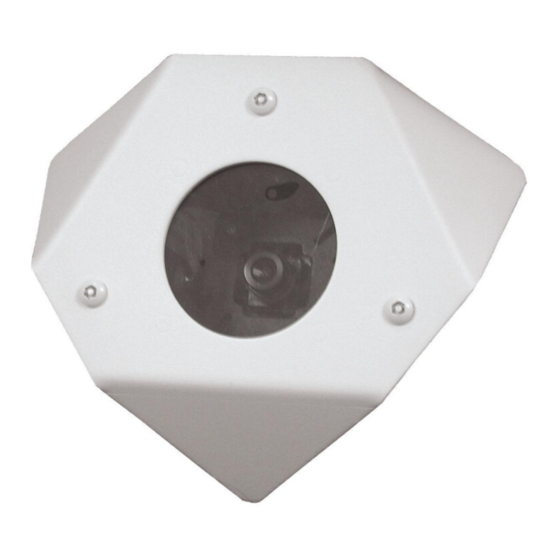
81-IN5219-06144 WARRIOR 6
WS6-XXXX
REVISION DATE: August 3, 2004
TABLE OF CONTENTS
CABLE AND POWER GUIDELINES
(Detailed info on Page 11)
This chart shows the proper current needed for power supplies for
Warrior Series cameras. Use Class 2 Power only. Input voltage
must be between 12-28 VDC or 15-28 VAC.
VOLTAGE
CURRENT
12 VDC
350mA
24 VAC
202mA
Depending on the voltage being used, refer to one of the formulas
below to select the correct power supply for cameras connected
in parallel (positive to positive, negative to negative):
Total current for a 12 VDC system:
TOTAL CURRENT = (350mA x total number of cameras)
Total current for a 24 VAC system:
TOTAL CURRENT = (202mA x total number of cameras)
INSTALLATION PREPARATION
INSTALLATION PREPARATION
1. Choose an appropriate corner location. The WS6 can be
mounted at any height in a corner.
2. Complete all wire and conduit runs prior to installation of
the housing.
1, 11
1
1
2
2
3
3
5
5
5
7
8
9
POWER
4.2W
4.8W
PRODUCT INSTRUCTIONS
INSTALLATION PROCEDURE
1. Using the security tool provided, loosen the (3) 10-32 security
fasteners and remove the face plate (Figure 1).
Figure 1
2. Place the back box into position and mark the four mounting
holes (Figure 2).
3. If you're using the top conduit knockout (Figure 2) REMOVE
THE CAMERA AND BRACKET TO PREVENT DAMAGE.
If using one of the side conduit knockouts it's not necessary to
remove the camera and bracket; however, use caution.
Top conduit knockout behind camera CAMERA MUST BE
REMOVED BEFORE USING
Mounting
Holes
Figure 2
4. Feed the wiring through the conduit knockout. A clamp
connector is included should you desire to use it. Install
the connector so that the nut is on the outside of the housing.
Be sure the hole in the wall is large enough to accommodate
the nut. Tighten the nut securely, making sure that the screw
heads on the connector are in an easy to reach position,
then feed the wiring through the clamp connector.
5. Mount the back box to the wall using appropriate hardware
(not provided).
NOTE: If the clamp connector was used, tighten the screws
at this time. Make sure enough wire is inside
the back box to complete the wiring process.
Mounting Holes
Advertisement
Table of Contents

Related Manuals for Moog Videolarm WS6-50NF


Summary of Contents for Moog Videolarm WS6-50NF
-
Page 1: Table Of Contents
81-IN5219-06144 WARRIOR 6 WS6-XXXX REVISION DATE: August 3, 2004 TABLE OF CONTENTS Cable and Power Guidelines Installation Preparation Installation Procedure Wiring Optional Warrior Test Monitor Cable 2 Camera Bracket Setup Camera Focusing Camera Settings Completion of Installation Window Guard™ Replacement NVT Instructions Warranty Information Service and Safeguard Information... -
Page 2: Wiring
WIRING (Figure 3) Use Class 2 Power only. Input voltage must be between 12-28 VDC or 15-28 VAC. 1. Connect the output of your Class 2 Power Supply to the terminal connectors on the PC Board inside the housing. Refer to the Troubleshooting section later in this instruction sheet for more information. -
Page 3: Camera Focusing
CAMERA FOCUSING (Figure 7) 1. The camera is factory equipped with a 3.6mm fixed lens. A 2.5mm lens is also provided. To remove the 3.6mm lens, loosen the set screw and unscrew the lens counter-clockwise. 2. Fine focusing of the lens: Loosen the set screw in the lens mount and manually rotate the lens until a clear picture is achieved. - Page 4 MC CAMERA DIP SWITCH SETTINGS CHART SWITCH SETTING Flickerless Mode Setting this switch to "On" and switch 3 (MIRIS) to "Off" will help to reduce the flicker in fluorescent lights BLC (Back Light Helps prevent an object from being washed out when the Compensation) object is directly in front of a light source.
-
Page 5: Completion Of Installation
COMPLETION OF INSTALLATION Reattach the front plate to the back box and tightly fasten the (3) security screws using the security tool. WINDOW GUARD™ PAINT SHIELD REPLACEMENT Your Warrior 6 comes with a replaceable Window Guard™ paint shield to protect the front plate window from vandalism. If vandalism occurs (spray paint, scratches, etc.) you need only replace the shield, not the entire window. - Page 6 Wiring Notes Wire — What to DO 1. DO use point-to-point Unshielded Twisted Pair wire, gauge 24 or thicker, stranded or solid, Category 2, 3, 4, or 5. 2. The video signal may co-exist in the same wire bundle as other video, telephone, data, control signals, or low-voltage power.
-
Page 7: Warranty Information
WS6 - Exploded Diagram and Replacement Parts List Part Number RPWS6010 RPWS6020 WS6PS RPWS6040 RPWS6050 RPWS6051 RPWS6052 RPWS6050P RPWS6051P RPWS6050P RPWS6060 RPWS6070 Description WARRIOR 6 FACE PLATE FASTENER KIT WARRIOR 6 FRONT PLATE ASSEMBLY WARRIOR 6 REPLACEMENT PAINT SHIELD WARRIOR 6 REPLACEMENT WINDOW KIT NTSC BOARD CAMERAS WARRIOR 6 STANDARD RES, BLACK &... -
Page 8: Service And Safeguard Information
1. The shipping carton and packaging material. They are the safest material in which to make future shipments of the equipment. 2. These Installation and Operating Instructions. LIMITED WARRANTY FOR VIDEOLARM INC. PRODUCTS VIDEOLARM INC. warrants this Product to be free from defects in material or workmanship, as follows: PRODUCT CATEGORY PARTS All Enclosures and Electronics Three (3) Years Pan/Tilts Three (3) Years **6 months if used in autoscan Poles/PoleEvators Three (3) Years Warrior/Q-View/I.R. Illuminators... -
Page 9: Troubleshooting
10 VAC or VDC. LINE LOCK All cameras are all shipped from the factory with the line lock function disabled. If your application requires Line Lock contact Videolarm. Primary Power - 10 -... - Page 10 NVT TROUBLESHOOTING If you are experiencing problems, attempt to simplify your setup. Test each cable segment separately. For example, test the camera and monitor together without the other equipment. Then add in the NVT transceivers, back-to-back. Test each segment of a long cable-run independently.
- Page 11 NOTE: The above table is based on a "worst-case" power supply. Using a regulated or switching power supply can increase your cable distance. A CSA/UL listed Class 2 power supply must be used. Videolarm recommends its PS12 12 VDC 1000mA power supply for...
Need help?
Do you have a question about the WS6-50NF and is the answer not in the manual?
Questions and answers