Tippmann A-5 E-GRIP KIT Installation & Tuning Instructions
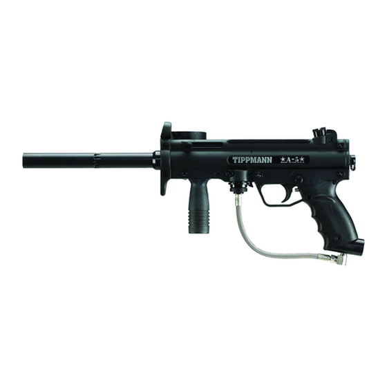
Paintball marker
Hide thumbs
Also See for A-5 E-GRIP KIT:
- Owner's manual (14 pages) ,
- Owner's manual (48 pages) ,
- Installation and operating instructions manual (20 pages)
Advertisement
Quick Links
Download this manual
See also:
Owner's Manual
A-5
TM
E-GRIP
TM
KIT
INSTALLATION
& TUNING
INSTRUCTIONS
EYE PROTECTION DESIGNED FOR PAINTBALL USE MUST BE WORN AT ALL TIMES WHEN HANDLING THIS
MARKER BY THE USER AND ANY PERSON WITHIN RANGE. DO NOT DISASSEMBLE THIS MARKER WHILE
IT IS PRESSURIZED WITH AIR. REMOVE AIR SUPPLY CYLINDER OR CARTRIDGE BEFORE DOING ANY
DISASSEMBLY. DISASSEMBLING THE RECEIVER WHILE UNDER AIR PRESSURE WILL CAUSE PERSONAL
INJURY & / OR DAMAGE TO THE MARKER.
DAMAGED. IF DURING THE COURSE OF THIS INSTALLATION, A PART IS LOST OR FOUND TO BE DAMAGED,
OBTAIN A REPLACEMENT PART BEFORE CONTINUING REASSEMBLY.
READ EACH STEP COMPLETELY BEFORE PERFORMING STEP
Set up a table with plenty of space to work.
You Will Need: Small screw driver, 1/8" allen wrench & 9 volt battery.
STEP 1: PREPARE MARKER FOR SAFE
DISASSEMBLY before beginning disassembly.
To do so, you must: (1-unload marker; (2-remove air source; (3-discharge
stored air; (4-uncock marker before further disassembly.
1) Unload your marker: first remove the hopper. Then, point your marker
in a safe direction and fire several times to be sure there are no balls left
in the feeder or lodged in the chamber.
2) Remove tank: To remove a charged air cylinder, turn the cylinder
approximately 3/4 of a turn counterclockwise or out. This allows the
tank pin valve to close so that no air will enter the marker. Point the
marker in a safe direction and fire the remaining air in the marker by
pulling the trigger until the marker stops firing. (This may take 4-5 shots)
If your marker keeps firing after you have turned the tank 3/4 of a
turn, the tank pin valve has not closed yet and you may have to turn the
tank counterclockwise a little further.
If you turn the tank 3/4 of a turn and it begins to leak before you
pull the trigger you have turned it too far and may have damaged the
tank o-ring.
3) After air tank is removed, point & fire the marker in a safe
direction until stored air is completely discharged.
4) Put the marker in the uncocked position: hold the bolt cocking
handle back - then pull the trigger and release handle forward to
un-cock the marker.
STEP 2: Remove Lower Receiver from upper receiver
1) To detach lower receiver: Remove 2 lower receiver push pins (#1
& #2) to detach from upper receiver.
STEP 3: Detach Tank Adapter from lower receiver.
1) To detach, remove receiver bolt (#3) from lower receiver.
(Store removed lower receiver in safe place).
STEP 4: Install Battery Into E-GRIP Kit Receiver
Follow Battery Installation Instructions on back page.
STEP 5: Inspect New E-GRIP Kit Lower Receiver.
1) Visually inspect new electric kit lower receiver. Check that the
trigger assembly is intact and the safety is in the "safe" (red not
showing - to the right) position.
Top view of trigger assembly intact - it should look like this...
Make sure no gaps
260/749-6022 • 800/533-4831 • FAX: 260/749-6619 • 2955 Adams Center Road • Fort Wayne, IN 46803 • INTERNET: www.tippmann.com
TIPPMANN
Safety Position
WARNING
DO NOT OPERATE THIS MARKER WITH PARTS MISSING OR
STEP 6: Attach Lower to Upper Receiver
1) Align lower receiver front push pin hole (#1) with
upper receiver hole (#1) then gently rock rear of grip
to align upper & lower push pin hole (#2).
2) With holes aligned, insert two lower receiver push
pins to attach.
STEP 7: Attach Tank Adapter to Lower Receiver
1) Remove (#3) receiver bolt from new lower
receiver. Slide tank adapter into lower receiver, align
holes then insert receiver bolt (#3) and tighten into
receiver bolt nut.
STEP 8: Install Tank Into Pistol Grip Tank Adapter
Note: Eye protection designed for paintball use must
be worn at all times when handling this marker by the
user and any person within range.
Standard Tank Installation Into Pistol Grip Adapter.
1) First, make sure that the marker is on SAFE mode.
Press safety "In" on left receiver half to lock trigger &
put marker in SAFE mode. (When safety button on left
side of marker shows red, the marker is in FIRE mode
and marker can fire.)
2) Next, cock the marker by sliding the bolt cocking
handle all the way back until you hear/feel the bolt lock
into place, then release the cocking handle to its forward
position.
3) To install the tank, insert the tank valve end into the
tank adapter at the back end of the pistol grip. Twist
the tank clockwise into the marker, until it stops. Adjust
the butt plate if necessary. Your marker is ready to fire
once you switch to FIRE mode from SAFE mode.
You are now ready to tune the A-5 E-GRIP rate of fire
and set the mode of fire.
TM
A-5 E-GRIP Kit
KIT CONTAINS
1 - Lower Receiver
Component
Receiver Reference
Upper Receiver
1
2
Lower
Receiver
Form# TP04001 Rev 06/21/2005
PN. 02-EG
Tank
Adapter
3
Advertisement

Related Manuals for Tippmann A-5 E-GRIP KIT


Summary of Contents for Tippmann A-5 E-GRIP KIT
- Page 1 You are now ready to tune the A-5 E-GRIP rate of fire Safety Position and set the mode of fire. 260/749-6022 • 800/533-4831 • FAX: 260/749-6619 • 2955 Adams Center Road • Fort Wayne, IN 46803 • INTERNET: www.tippmann.com Form# TP04001 Rev 06/21/2005...
- Page 2 Right Trigger (under battery) Slider, Spring Armature plate with parts & Pin. to position wires for If a problem still exists, call shown in position capacitor & solenoid Tippmann Service Department at 1-800-533-4831.
Need help?
Do you have a question about the A-5 E-GRIP KIT and is the answer not in the manual?
Questions and answers