Table of Contents
Advertisement
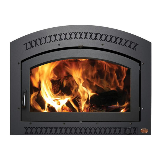
• Built-In Direct Vent Fireplace
• Natural Gas or Propane
• Residential or Mobile Home
WARNING:
Improper installation, adjustment, alteration, service or maintenance can cause
injury or property damage. Refer to this manual. For assistance or additional
information consult a qualified installer, service agency, or the gas supplier.
-
Do not store or use gasoline or other flammable vapors and liquids in the vicinity of this or
any other appliance.
-
Installation must be performed by a qualified installer, service agency or the gas supplier
IF YOU SMELL GAS
• Do not try to light any appliance.
• Do not touch any electrical switch; do not use any phone in your building.
• Immediately call gas supplier from a neighbor's phone. Follow the gas supplier's instructions.
• If you cannot reach your gas supplier, call the fire department.
36 DV EFIII Owner's Manual
Installer: After installation give this manual to the home-owner and
explain operation of this fireplace.
$10.00
Copyright 2005 Travis Ind.
# 100-01160
4050923
TM
Featuring the
Burner
Tested and Listed by
Omni-Test Laboratories, Inc.
Beaverton, Oregon
Report # 028-S-20b-1
ANSI Z21.88, CSA 2.33 MR 8,
CAN/CGA 2.17-M91
4800 Harbour Pointe Blvd. SW
Mukilteo, WA 98275
Advertisement
Table of Contents

Related Manuals for FireplaceXtrordinair 36 DV EFIII


Summary of Contents for FireplaceXtrordinair 36 DV EFIII
- Page 1 • Immediately call gas supplier from a neighbor's phone. Follow the gas supplier's instructions. • If you cannot reach your gas supplier, call the fire department. 36 DV EFIII Owner’s Manual Installer: After installation give this manual to the home-owner and explain operation of this fireplace.
-
Page 2: Introduction & Important Information
Model: Serial Number: Purchase Date: Purchased From: Travis Industries Introduction 36 DV EFIII 4040708 Mail your Warranty Card Today, and Save Your Bill of S a l e . To receive full warranty coverage, you will need to show evidence of the date you purchased your heater. -
Page 3: Table Of Contents
Table of Contents Introduction Introduction & Important Information...2 Safety Precautions Safety Precautions ...4 Features & Specifications Features ...6 Installation Options ...6 Heating Specifications ...6 Dimensions...6 Installation Installation Warning...7 Packing List...7 Additional Items Required for Installation ...7 Installation Overview ...7 Fireplace Placement Requirements...8 Minimum Framing Dimensions ...8 Clearances ...8 Corner Installations ...9... -
Page 4: Safety Precautions
Safety Precautions • IF YOU SMELL GAS: * Do not light any appliance * Extinguish any open flame * Do not touch any electrical switch or plug or unplug anything * Open windows and vacate building * Call gas supplier from neighbor's house, if not reached, call fire •... - Page 5 Safety Precautions • Do not place clothing or other flammable items on or near the heater. Because this heater can be controlled by a thermostat there is a possibility of the heater turning on and igniting any items placed on or near it. •...
-
Page 6: Features & Specifications
Features and Specifications Features: Works During Power Outages (millivolt system) High Efficiency Optional Thermostat or Remote Control Realistic "Wood Fire" Look Quiet Blower for Effective Heat Distribution Convenient Operating Controls Variable-Rate Heat Output Low Maintenance Heating Specifications: Approximate Heating Capacity (in square feet)* Maximum BTU Input Per Hour Minimum BTU Output on Low (with blowers on) Efficiency** (with blowers on) -
Page 7: Installation
Installation Installation Warnings: Failure to follow all of the requirements may result in property damage, bodily injury, or even death. This heater must be installed by a qualified installer who has gone through a training program for the installation of direct vent gas appliances. This appliance must be installed in accordance with all local codes, if any;... -
Page 8: Fireplace Placement Requirements
Installation Fireplace Placement Requirements Minimum Framing Dimensions A 1/2" clearance is required along the sides and back of the fireplace. The 1/2" stand-offs on the sides and 6-1/4" stand-offs on the top of the fireplace are designed to separate the fireplace from the framing members. -
Page 9: Corner Installations
Installation Corner Installations A typical 45° installation uses the minimum framing dimensions shown in the illustration below (NOTE: all clearances still apply). 14-1/2" 46-1/4" Raised Fireplaces • The fireplace (and hearth, if desired) may be placed on a platform designed to support the fireplace (250 Lbs.) and vent. -
Page 10: Hearth Requirements
Installation Hearth Requirements Hearth Requirement: Raised Fireplaces Travis Industries (for qualified installers only) Floor Mounted Fireplaces The hearth must tuck underneath this ledge. 4040708 Fireplace 1 0 0 - 0 1 1 6 0... -
Page 11: Facing Requirements
Installation Facing Requirements NOTE: The combustible area above the facing must not protrude more than 3/4" from the facing. If it does, it is considered a mantel and must meet the mantel requirements listed in this manual. WARNING : Do not use adhesive to secure the cement board or facing. The high temperatures of the fireplace may cause adhesives to emit odors. -
Page 12: Facing Detail
Installation Facing Detail Do not tuck tile underneath the face on the bottom (there will be a 1/2" air space below the access door). You may do this on the sides and top, but not on the bottom. • To achieve a facing that is flush with the drywall to the side of the fireplace, recess the framing directly next to the fireplace. -
Page 13: Face Dimensions
Installation Face Dimensions Classic Arched (Gold, Black, or Artisan*) 5" Radius = 35” 29" Access Door 36” * Artisan faces may vary slightly in size due to the forging process. Modifying the Face Angle for Rectangular Faces If using a rectangular face, adjust the face angles at the top corners of the glass (see the illustration below). -
Page 14: Facing And Hearth Examples
Installation Facing and Hearth Examples Side View SUGGESTION: If using a hearth, make your platform height a dimension that will accommodate the size tiles you are using and the 1" between the base of the fireplace and the bottom of the face. 3/8"... - Page 15 Installation Facing and Hearth Examples (continued) Side View 3/8" Thick Tile 1/2" Cement Board Wood Sub Floor Three-Dimensional View Face NOTE: When hearth installation is correctly completed, there will be a 1/2" air space below the access door on the face. Do not block this air space (it is required for access door opening and proper air flow).
-
Page 16: Mantel Requirements
Installation Mantel Requirements • The combustible area above the facing must not protrude more than 3/4" from the facing. If it does, it is considered a mantel and must meet the mantel requirements listed in this manual. Combustible Mantels 28-1/2" Rectangular face 30-3/8”... -
Page 17: Vent Requirements
Installation Vent Requirements The vent must maintain the required clearance to combustible materials to prevent a fire (see “Clearances” below). Do not fill air spaces with insulation. The gas appliance and vent system must be vented directly to the outside of the building, and never be attached to a chimney serving a separate solid fuel or gas-burning appliance. -
Page 18: Vent Installation
Installation Vent Installation • In addition to the requirements below, follow the requirements provided with the vent. Vertical Termination Use a roof flashing and storm collar whenever passing through the roof Use a firestop whenever passing through a ceiling 8-5/8" 10"... -
Page 19: Approved Vent Configurations
Installation Approved Vent Configurations Restrictor Position • A vent restrictor is built into the appliance to adjust the flow rate of exhaust gases. This ensures proper combustion for all vent configurations. Depending upon the vent configuration, you may be required to adjust the restrictor position. The charts for acceptable vent configurations detail the correct vent restrictor position. -
Page 20: Vertical Term. 0,2 Or 4 45° Offsets (6-5/8")
Installation Vertical Terminations with 0, 2, or 4 45° Offsets using 6-5/8” Dia. Vent • Use 6-5/8” diameter co-axial vent • A Maximum of Four 45° Elbows May be Used • 10' Minimum System Height (with or without offsets) • 40' Maximum System Height •... -
Page 21: Hor. Terminations With 6-5/8" Dia. Vent
Installation Horizontal Terminations using 6-5/8” Diameter Vent Use a single 90° elbow (NOTE: an additional 45° elbow may be used on the horizontal run). 10' (max) The termination must fall within the shaded area shown in the 5 feet chart. Use the indicated restrictor position. -
Page 22: Vert. Term. With 2 Or 3 Elbows (6-5/8" Dia.)
Installation Vertical Terminations with Two or Three 90° Elbows Using 6-5/8” Dia. Vent The termination must fall within the shaded area shown in the chart. Use the indicated restrictor position. 40' (max) 35 feet 30 feet 25 feet 20 feet 15 feet 10 feet (min.) -
Page 23: Horizontal Terminations With 8" Dia. Vent
Installation Horizontal Terminations using 8” Diameter Vent The termination must fall within the shaded area shown in the chart. Use the indicated restrictor position. 20' (max) 15 feet 10 feet 5 feet 6-5/8" to 8" dia. Adapter (must be placed directly off the top of the fireplace - Part # 925T) 0 feet NOTE:... -
Page 24: Vent Termination Requirements
Installation Termination Requirements (see the illustration below) Minimum 9" clearance from any door or window Minimum 12" above any grade, veranda, porch, deck or balcony Minimum 12" from outside corner walls Minimum 12" from inside corner walls Minimum 11" clearance below unventilated soffits or roof surfaces Minimum 18"... -
Page 25: Gas Line Requirements
Installation Gas Line Requirements The gas line must be installed in accordance with all local codes, if any; if not, follow ANSI 223.1 and the requirements listed below. The fireplace and gas control valve must be disconnected from the gas supply piping during any pressure testing of that system at test pressures in excess of 1/2 psig. -
Page 26: Electrical Connection
Installation Electrical Connection Make sure the household breaker is shut off prior to working on any electrical lines. The fireplace must be properly grounded in accordance with local codes (or ANSI/NFPA 70-1987) • The electrical line must be 14 gauge, and supply 120 Volts at 60 Hz (2 Amps) Follow the directions below to connect power to the fireplace. -
Page 27: Finalizing The Installation
Finalizing the Installation Remove the glass frame (and arch covers) following the directions below. Warning: The appliance must be completely cool before removing the glass. Note: If using an arch face, attach the arch covers after re-installing the glass. Open the four latches holding the glass frame in place (start with the bottom two) - follow the directions shown to the right. - Page 28 Finalizing the Installation Glass Frame Removal (continued) - Spring Pin Installation The spring pin can come loose from the latch assembly. This occurs when it is turned 1/4 turn when it is disengaged. Follow the directions below to re-install the spring pin if it becomes loose. NOTE: The spring pins can be installed with the glass frame in place or...
-
Page 29: Top View
Step 1 Install the logs (see the illustration below). Place the rear log on the two platforms at the rear of the firebox. Place the front logs on top of the burner. These bolts insert into the holes in the logs. Do not place logs over burner holes. -
Page 30: Front View
Step 2 Install the twigs and ember chunk (see the illustration below). Place the left and right twigs as shown. Step 3 Install the embers along the front of the burner (see the illustrations below). Do not place the embers over the burner holes. Front View We recommend you purge the gas line at this time (with the glass removed). -
Page 31: Leak Test
Let the heater burn for fifteen minutes. Adjust the air shutters, if necessary, to achieve the correct looking flame (see the illustration below). • The air shutter adjusts the amount of air that mixes with the gas before it exits the burner holes. ADJUSTING THE AIR SHUTTERS Pushing the control to the left gives the flame less air (making it more orange). -
Page 32: Check Flame
Turn the flame adjust knob to its highest position - the flames should be approximately 10" tall. Check the flame on low position. The flames should burn off of each burner hole. If the heater does not work correctly, contact your dealer for a remedy. -
Page 33: Operation
Before You Begin Read this entire manual before you use your new fireplace (especially the section "Safety Precautions" on pages 4 & 5). Failure to follow the instructions may result in property damage, bodily injury, or even death. Location of Controls - See explanation below The pilot flame is located below the rear log. -
Page 34: Starting The Pilot
Starting The Pilot Flame The pilot flame is required to ignite the main burners (it also plays a safety role). It should be left on once lit. It will stay lit unless the gas control valve is turned to "OFF". However, the pilot will go out if the gas is shut off, the propane tank runs out (or low) or if the stove malfunctions. -
Page 35: Starting The Fireplace For The First Time
Turning the Fireplace On and Off After the pilot has been started... Use this switch to turn the main burner on and off manually. Do not place any combustible items on top of or directly in front of the fireplace, even temporarily. The optional thermostat may start the fireplace causing a combustible item to ignite. -
Page 36: Adjusting The Blower Speed
This part can produce a clicking sound as it turns the blower on and off. Extinction Pops It is not unusual, especially on Propane (LP) appliances, to experience a "pop" when the burner is shut off. 4040708 Turn the dial all the way clockwise. -
Page 37: Maintenance
Clean the air channels and ducts. Start the pilot and turn on the main burner. The flames should be orange/yellow and not touch the top of the firebox. If the pilot or main burners do not burn correctly, contact your dealer for service. Monitor the blower operation. -
Page 38: Troubleshooting Table
Troubleshooting Table Problem: Pilot Will Not Light Main Burners Will Not Start Remote Control Does Not Work Thermostat Does Not Work Fireplace Will Not Distribute Heat Pilot Goes Out Once A Month Or More Flames Are Too Blue Flames Are Too Short (Under 6") Thin Layer of Soot Covers the Glass... -
Page 39: How This Fireplace Works
The ON/OFF switch, remote control, or thermostat control the circuit to the main burner. Ceramic Glass The glass in your heater is the most durable glass available. It has been tested to be extremely resistant to breakage from temperature changes. -
Page 40: Wiring Diagram
LOG CHUNKS, LS8 - 2001 # LOG SET, LS13 - SIX PIECE # MAGNET w/OUT SHEATH # ORIFICE, BURNER - No. 43 # ORIFICE, BURNER - No. 46 # ORIFICE, BURNER - No. 54 # ORIFICE, BURNER - No. 55... -
Page 41: Safety (Listing) Label
Safety Label The safety (listing) label is adhered to the base of the fireplace near the gas control valve. A copy of the safety label is shown below. Travis Industries 4040708 1 0 0 - 0 1 1 6 0... -
Page 42: Warranty
Adjustable Air Restrictor, Pressure Relief Mechanisms, Glass Frame and Latch Exclusions: Paint, Gasketing, Burner Assembly, Electrical Assembly, Gas Control Assembly, Ceramic Glass, Ceramic Logs, Convection Heat Exchanger, Accessories (Fireback, Panels, Faceplate), Re-Installation Allowance, One-Way Freight Allowance, Labor CONDITIONS & EXCLUSIONS This new gas appliance must be installed by a qualified gas appliance technician. -
Page 43: Lp Conversion Instructions
(lift the burner from below). Pull the burner forward, out of the firebox. Burner Replacement: Make sure the burner is fully seated. When in place, the pilot flame must align directly above the burner holes. Make sure the mixing tubes slide onto the orifices. - Page 44 Optional Equipment Follow the directions below to replace the orifices. Use a 1/2” open end wrench to unscrew both orifices. Front Burner Orifice Remove the pilot orifice following the instructions below. Replace with the propane pilot orifice Lift the pilot hood off the pilot assembly.
- Page 45 Make the gas line connection, bleed the gas line (if applicable), start the heater and thoroughly leak- test all gas connections and the gas control valve. Check the pilot. Adjust if necessary.
-
Page 46: Power Heat Duct
Optional Equipment POWER HEAT DUCT The optional heat duct allows the fireplace to transfer heat to separate locations in the home. One or two ducts may be used . Installation should take place prior installing drywall. Warning: This kit must be installed as specified in these instructions. Do not modify any component. -
Page 47: Floor Mounting
Optional Equipment Attach the blower box to the framing or floorboards of the home following the instructions below. Wall or Ceiling Mounting Cut a hole between wall framing members for the blower assembly. 16"* 5-1/4" * This blower was designed for framing on 16" centers - construct additional framing if needed. - Page 48 Optional Equipment Attach the starter ring to the fireplace following the directions below (use the most convenient side). Install the air duct. Each section, when joined, must be attached with three screws and duct tape (U.L. 181A-P or equivalent). Secure the duct if it is in an area where it may sag or become dislodged. NOTE: The air duct has a 0”...
- Page 49 Optional Equipment Attach the grill (and wall adapter, if necessary). Screws (included with this kit) Phillips Screwdriver WIRING INSTRUCTIONS Warning: All wiring should be done by a qualified electrician and shall be in compliance with local codes and with the current National Electric Code ANSI/NFPA 70 (in the U.S.), or with the current CSC22.1 Canadian Electric Code (in Canada).
- Page 50 Optional Equipment Follow the directions below to wire the blower box. Remove the cover from the blower box. Attach the hot (black) and common (white) wires to the leads coming from the wires (use wire nuts). Follow the directions below to wire the rheostat. NOTE: There are two types of junction boxes, use the appropriate junction box for your installation.
-
Page 51: Maintenance Instructions
Optional Equipment Run the free wire from the rheostat junction box to the fireplace. Follow the directions below to connect the heat duct circuit to the fireplace. Remove the cover from the fireplace junction box. Note: you may need to loosen this cable clamp to ease removal of the cover plate. -
Page 52: Index
Approved Vent Configurations...18 Adjusting the Blower Speed...35 Adjusting the Flame Height ...34 Air Shutter Adjustment...31 Altitude Considerations...16 Blower Control...35 BTU Input...5 BTU Output...5 Cap (see vent termination)...23 Chimney Cap (see vent termination)...23 Chimney Installation (see Vent Requirements)...16 Clearances...7 Condensation on Glass...35 Corner Installation...8 Dimensions...5 Dura-Vent (part numbers)...16...
Need help?
Do you have a question about the 36 DV EFIII and is the answer not in the manual?
Questions and answers