Table of Contents
Advertisement
WARNING:
If the information in these instructions are not followed exactly, a fire or
explosion may result causing property damage, personal injury or loss of life.
-
Do not store or use gasoline or other flammable vapors and liquids in the vicinity of this or
any other appliance.
WHAT TO DO IF YOU SMELL GAS
• Do not try to light any appliance.
• Do not touch any electrical switch; do not use any phone in your building.
• Immediately call gas supplier from a neighbor's phone. Follow the gas supplier's instructions.
• If you cannot reach your gas supplier, call the fire department.
-
Installation and service must be performed by a qualified installer, service agency or the gas
supplier.
This appliance may be installed as an OEM installation in a manufactured (mobile) home and
must be installed in accordance with the manufacturer's instructions and the manufactured
home construction and safety standard, Title 24 CFR, Part 3280 or Standard for Installation in
Mobile Homes, CAN/CSA Z240 MH.
This appliance is only for use with the type(s) of gas indicated on the rating plate. A conversion
kit is supplied with the appliance.
Installer: After installation give this manual to the home-
owner and explain operation of this fireplace.
$10.00
Copyright 2003, T.I.
(CB) Owner's Manual
Part # 93508116
TM
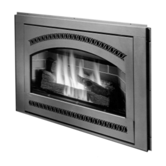
35 Custom Builder
Tested and Listed by
Omni-Test Laboratories, Inc.
Beaverton, Oregon - Report # 028-5-35-5
ANSI Z21.88, CSA 2.33 M9 8, CAN/CGA 2.17-M91
•
Direct Vent Fireplace
• Natural Gas or Propane
• Standard Residential
• Mobile Home Approved
10850 117th Place N.E. Kirkland, WA 98033
Advertisement
Table of Contents

Related Manuals for FireplaceXtrordinair 35 Custom Builder


Summary of Contents for FireplaceXtrordinair 35 Custom Builder
- Page 1 35 Custom Builder (CB) Owner’s Manual Tested and Listed by Omni-Test Laboratories, Inc. Beaverton, Oregon - Report # 028-5-35-5 ANSI Z21.88, CSA 2.33 M9 8, CAN/CGA 2.17-M91 • Direct Vent Fireplace • Natural Gas or Propane • Standard Residential • Mobile Home Approved...
-
Page 3: Important Information
Introduction Introduction We welcome you as a new owner of a Fireplace Xtrordinair gas fireplace. In purchasing a Fireplace Xtrordinair you have joined the growing ranks of concerned individuals whose selection of an energy system reflects both a concern for the environment and aesthetics. The Fireplace Xtrordinair is one of the finest fireplaces the world over. -
Page 4: Safety Precautions
Safety Precautions • IF YOU SMELL GAS: * Do not light any appliance * Extinguish any open flame * Do not touch any electrical switch or plug or unplug anything * Open windows and vacate building * Call gas supplier from neighbor's house, if not reached, call fire department •... - Page 5 Safety Precautions • Do not place clothing or • Light the fireplace using the other flammable items on or built-in piezo igniter. Do not near the fireplace. Because use matches or any other this fireplace can be external device to light your controlled by a thermostat fireplace.
-
Page 6: Table Of Contents
Table of Contents Introduction Finalizing the Installation Introduction & Important Information....1 Glass Removal (& installation) ......24 Log Installation..........25 Safety Precautions Leak Test ...........26 Safety Precautions ........2 Pilot Adjustment (if necessary) .......26 Features & Specifications Air Shutter Adjustment (if necessary)....26 Check Flame ..........27 Features ............5 Explain Operation to Home-Owner ....27 Installation Options ........5... -
Page 7: Features & Specifications
Features and Specifications Features: Installation Options: Works During Power Outages (millivolt system) Residential or Mobile Home High Efficiency Straight or Corner Placement Optional Thermostat or Remote Control Flush or Recessed Face Realistic "Wood Fire" Look Raised or Floor Hearth Optional Blower for Heat Distribution Internal or External Chase Convenient Operating Controls Horizontal or Vertical Vent... -
Page 8: Installation
Installation (for qualified installers only) Installation Warnings: Failure to follow all of the requirements may result in property damage, bodily injury, or even death. This fireplace must be installed by a qualified installer who has gone through a training program for the installation of direct vent gas appliances. This appliance must be installed in accordance with all local codes, if any;... -
Page 9: Fireplace Placement Requirements
Installation (for qualified installers only) Fireplace Placement Requirements Minimum Framing Dimensions The 1/2” stand-offs along the sides and back, and the 2-1/2" stand-offs on top of the fireplace separate the fireplace from combustible materials (e.g.: combustible framing members, plywood, sheetrock, paper-backed insulation). The stand-offs may contact the framing members but no material may be placed between the stand-offs. -
Page 10: Corner Installations
Installation (for qualified installers only) Corner Installations A typical 45° installation uses the minimum framing dimensions shown in the illustration below (NOTE: all clearances still apply). 12-3/8" 13-1/2" Fireplace (includes 1/2" 40-1/2" standoffs) 39-7/8" 57-3/8" 8-3/4" Raised Fireplaces • The fireplace (and hearth, if desired) may be placed on a platform designed to support the fireplace (approximately 300 Lbs.) and vent. -
Page 11: Hearth Requirements
Installation (for qualified installers only) Hearth Requirements • The fireplace must be placed on a wood or non-combustible sub-floor. • No hearth is required. N O T E : Carpeting or other floor covering (e.g. linoleum, wood flooring) must not protrude 3/4" above the base of the fireplace. -
Page 12: Facing Requirements
Installation (for qualified installers only) Facing Requirements • Drywall may be butted up to the drywall standoff. N O T E : Drywall or other combustibles may not be placed over the drywall standoff. N O T E : No drywall or other combustible may protrude farther than 3/4" in front of the drywall standoff. Any combustible material that protrudes 3/4"... -
Page 13: Facing Detail For 35 Cb Faces
Installation (for qualified installers only) Facing Detail for 35 CB Face Flush Facing - Top View Tile Facing - Top View Recessed Tile Facing - Top View Flange on Framing Framing Framing Drywall Flange on Flange on Standoff Drywall Drywall Fireplace Fireplace Fireplace... -
Page 14: Facing Detail For 36 Dv Faces
Installation (for qualified installers only) Facing Detail for 36 DV Faces Tile Facing - Top View Drywall Framing NOTE: The press-nut on Standoff the mounting bracket protrudes behind the Flange on Drywall bracket and interferes Standoff with tile placement. Fireplace 1/2"... -
Page 15: Face Installation - 35 Cb Face
Installation (for qualified installers only) Face Installation - 35 CB Face Hang the 35 CB Face on the screws and bushings at the top inside of the drywall standoff. Phillips Screwdriver Secure the face with these two screws (the screws are attached to the fireplace). Travis Industries 9 3 5 0 8 1 1 6 0 3 1 0 0 0... -
Page 16: Face Installation & Sizing - 36 Dv Face
Installation (for qualified installers only) Face Installation & Sizing - 36 DV Faces (requires part # 98500536) Steps for installing 36 DV Faces With the fireplace in place and glass removed, install the tile stop for the type of Tile Stop for face used (see illustration to the right) - included with kit # 98500536. -
Page 17: Mantel Requirements
Installation (for qualified installers only) Mantel Requirements • Any combustible material above the face must not protrude more than 3/4" from the facing material. If it does, it is considered a mantel and must meet the mantel requirements listed below. Max. -
Page 18: Vent Requirements
Installation (for qualified installers only) Vent Requirements The vent must maintain the required clearance to combustible materials to prevent a fire (see “Clearances” below). Do not fill air spaces with insulation. The gas appliance and vent system must be vented directly to the outside of the building, and never be attached to a chimney serving a separate solid fuel or gas-burning appliance. -
Page 19: Vent Installation
Installation (for qualified installers only) Vent Installation • In addition to the requirements below, follow the requirements provided with the vent. Vertical Termination Vertical Vent Requirements Use a roof flashing and storm collar whenever passing through the roof Use a firestop whenever passing through a ceiling Maintain a minimum 1"... -
Page 20: Approved Vent Configurations
Installation (for qualified installers only) Approved Vent Configurations Restrictor Position • A vent and intake restrictor is built into the appliance to adjust the flow rate of exhaust gases. Depending upon the vent configuration, you may be required to adjust the restrictor position. The charts for acceptable vent configurations detail the correct vent restrictor position. -
Page 21: Vertical Term. 0, 2, Or 4 45° Offsets
Installation (for qualified installers only) Vertical Terminations with Zero, Two, or Four 45° Offsets Offset Length Hor. Offset Vert. Rise Horizontal Offset None 5" 1' Section 1' 7" Vertical Rise 2' Section 1' 9" 2' 4" 3' Section 2' 5" Offset 4' Section 3' 2"... -
Page 22: Horizontal Term. With One Elbow
Installation (for qualified installers only) Horizontal Terminations with One Elbow The termination must fall within the shaded area shown in the chart. Use the indicated restrictor position. 10 feet 10 feet (max) (max) Restrictor Position # 1 5 feet 5 feet 0 feet 0 feet NOTE:... -
Page 23: Vertical Term. With Two Elbows
Installation (for qualified installers only) Vertical Terminations with Two 90° Elbows The termination must fall within the shaded area shown in the chart. Use the indicated restrictor position. 40' (max) 40' (max) 35 feet 35 feet Restrictor Position # 8 30 feet 30 feet 25 feet... -
Page 24: Vent Termination Requirements
Installation (for qualified installers only) Termination Requirements (see the illustration below) Venting terminals shall not be recessed into a wall or siding. Minimum 9" clearance from any door or window Roof Minimum 12" above any grade, veranda, porch, deck or balcony Surface Minimum 12"... -
Page 25: Gas Line Requirements
Installation (for qualified installers only) Gas Line Requirements The gas line must be installed in accordance with all local codes, if any; if not, follow ANSI 223.1 and the requirements listed below. The fireplace and gas control valve must be disconnected from the gas supply piping during any pressure testing of that system at test pressures in excess of 1/2 psig. -
Page 26: Glass Removal (& Installation)
Finalizing the Installation (for qualified installers only) Remove the face (see page 13 or 14). Remove the glass assembly following the directions below. Warning: The appliance must be completely cool before removing the glass. Warning: To prevent damage, do not abuse, strike, or slam the glass frame. Note on Arch Covers (both sides) The arch covers... -
Page 27: Log Installation
Finalizing the Installation (for qualified installers only) If converting this unit to propane, do so now (see the instructions on page 38). If installing the fireback, do so now (see the instructions on page 41) Install the log set, kibbles, and glowing embers (see the instructions included with the embers). Warning: Failure to position the parts in accordance with these diagrams or failure to use only parts specifically approved with this appliance may result in property damage or personal injury. -
Page 28: Finalizing The Installation
Finalizing the Installation (for qualified installers only) We recommend you purge the gas line at this time (with the glass removed). This allows gas to be detected once it enters the firebox, ensuring gas does not build up. Turn on the gas to the fireplace. Turn on gas to the fireplace. Leak test all gas joints prior to starting the appliance. -
Page 29: Check Flame
Finalizing the Installation (for qualified installers only) If the vent configuration is installed incorrectly the vent may cause the flames inside the fireplace to lift or "ghost" – a dangerous situation. Inspect the flames after installation to insure proper performance. If the vent configuration is correct, yet the flames are lifting or ghosting, shut off gas to the fireplace and contact the dealer for information on remedying the problem. -
Page 30: Operation
Operation Before You Begin Warning: Read this entire manual before you use your new fireplace (especially the section "Safety Precautions" on pages 2 & 3). Failure to follow the instructions may result in property damage, bodily injury, or even death. Warning: Do not operate appliance with the glass front removed, cracked or broken. -
Page 31: Starting The Pilot
Operation Starting The Pilot Flame The pilot flame is required to ignite the main burners (it also plays a safety role). It should be left on once lit. It will stay lit unless the gas control valve is turned to "OFF". However, the pilot will go out if the gas is shut off, the propane tank runs out (or low) or if the stove malfunctions. -
Page 32: Starting The Fireplace For The First Time
Operation Starting the Fireplace for the First Time Burn the fireplace at a high setting with the blower off for an extended period (up to 48 hours). This will cure the painted surfaces. Fumes from the paint curing and oil burning off the steel will occur. This is normal. -
Page 33: Adjusting The Blower Speed
Operation Adjusting the Blower Speed (Optional) The internal blower helps transfer Blower Knob the heat from the fireplace into the room. It will not turn on until the Turn the knob all the way counter-clockwise to turn fireplace is up to temperature the blower off. -
Page 34: Maintenance
Maintenance (for qualified service personnel only) Maintaining Your Fireplace's Appearance Fingerprints or other marks left on the optional gold surface may become etched in place if they are not wiped clean prior to turning the fireplace on. Clean gold with denatured alcohol and a soft cloth (make sure the fireplace is cool). -
Page 35: Troubleshooting Table
Maintenance (for qualified service personnel only) Troubleshooting Table Problem: Possible Cause: Don't Call for Service Until You: A gas shut off valve is turned off Check all gas shut off valves Pilot Will Not Light The gas control knob isn't turned to "PILOT" See "Starting the Pilot Light"... -
Page 36: How This Fireplace Works
Maintenance (for qualified service personnel only) How this Fireplace Works This fireplace was designed with safety as the primary concern. Many of the components inside this fireplace are for safety purposes. Therefore, only certified gas service technicians should service this fireplace. -
Page 37: Wiring Diagram
Maintenance (for qualified service personnel only) Wiring Diagram Caution: Label all wires prior to disconnection when servicing controls. Wiring errors can cause improper and dangerous operation. Thermopile Thermocouple Piezo Igniter Millivolt Wiring On/Off Switch (for gas control valve) Brown Copper Co-Axial Wire Orange Spark Electrode... -
Page 38: Safety (Listing) Label
The safety (listing) label is on a plate chained to the gas control valve. A copy of the safety label is shown below. Minimum Clearances to Combustibles Model 35 Custom Builder (CB) Fireplace Edge of Glass Frame to Adjacent Wall ..8-1/2” (216mm) Hearth Extension in Front . -
Page 39: Warranty
Warranty To register your TRAVIS INDUSTRIES, INC. 7 Year Warranty, complete the enclosed warranty card and mail it within ten (10) days of the appliance purchase date to: TRAVIS INDUSTRIES, INC., 10850 117th Place N.E., Kirkland, Washington 98033. TRAVIS INDUSTRIES, INC. warrants this gas appliance (appliance is defined as the equipment manufactured by Travis Industries, Inc.) to be defect-free in material and workmanship to the original purchaser from the date of purchase as follows: Years 1 &... -
Page 40: Optional Equipment
Optional Equipment (for qualified installers only) LP Conversion Instructions Install the conversion kit prior to installing the gas line to ensure proper gas use. Remove the glass (see page 24). Remove the logs and kibbles (if installed - page 25) Remove the burner (see illustration to the right). - Page 41 Optional Equipment (for qualified installers only) Follow the directions below to remove the natural gas orifices. Apply thread sealant to the LP orifices and tighten them in place with a 1/2" open end wrench (make sure to install the orifices correctly – see the illustration below).
- Page 42 Optional Equipment (for qualified installers only) Remove the pilot orifice following the instructions below. Replace with the propane pilot orifice. The propane conversion kit includes pilot orifice with "35" stamped on it. Replace burner pan. Remove the orifice and replace with the LP orifice. Screw the Lift the pilot hood off the pilot orifice all the way in and replace the pilot hood.
- Page 43 Optional Equipment (for qualified installers only) Make the gas line connection, bleed the gas line (if applicable), start the heater and thoroughly leak- test all gas connections and the gas control valve. Check the pilot. Adjust if necessary. WARNING: When lighting or re-lighting the pilot, the glass must be removed (see page 24).
-
Page 44: Blower
Optional Equipment (for qualified installers only) Face Mounting Kit (for mounting 36 DV Faces) (part # 98500536) See the instructions on page 14. Blower (part # 99000155) Do not connect 110-120 VAC to the gas control valve or wiring system of this unit. Attach the rheostat bracket to the fireplace following the directions below. - Page 45 Optional Equipment (for qualified installers only) Install the bushings into the grommets on the blower following the directions below. Insert the bushings into these two grommets. Make sure the four grommets on the base of the blower assembly are in place (they dampen the blower, keeping it quiet).
- Page 46 Optional Equipment (for qualified installers only) Attach the on/off wires to the valve following the directions below. Attach these two wires to the front of the gas control valve. Install the electrical connection to the fireplace following the directions below. Insert the sheathed cable from the power source through Remove the cover from the this cable clamp.
- Page 47 Optional Equipment (for qualified installers only) Travis Industries 9 3 5 0 8 1 1 6 0 3 1 0 0 0...
-
Page 48: Index
Index Approved Vent Configurations......18 Installation Options ...........5 Adjusting the Blower Speed......31 Items Required for Installation......6 Adjusting the Flame Height .......30 Leaking Gas ......See Inst. on Cover Air Shutter Adjustment........26 Listing Information ..........36 Altitude Considerations........16 Location of Controls..........28 Blower Control..........31 Log Set Installation and Removal .......25 BTU Input............5 Maintenance ............32 BTU Output............5...
Need help?
Do you have a question about the 35 Custom Builder and is the answer not in the manual?
Questions and answers